Cisco CRS-1 Carrier Routing System Fiber-Optic Cleaning Guide
Bias-Free Language
The documentation set for this product strives to use bias-free language. For the purposes of this documentation set, bias-free is defined as language that does not imply discrimination based on age, disability, gender, racial identity, ethnic identity, sexual orientation, socioeconomic status, and intersectionality. Exceptions may be present in the documentation due to language that is hardcoded in the user interfaces of the product software, language used based on RFP documentation, or language that is used by a referenced third-party product. Learn more about how Cisco is using Inclusive Language.
- Updated:
- March 20, 2015
Chapter: Overview
Overview
The Cisco CRS-1 fiber-optic cleaning kit (CRS-FIBER-CLN-KIT=) is used to clean all multiferrule (MT) optics in a Cisco CRS-1 Carrier Routing System Multishelf System using the Cisco CRS-1 fiber-optic cleaning kit. This kit cleans all optics on the S2 module, S13 module, optical interface module (OIM), and optical array cables.
The cleaning tool included in the kit advances a continuous roll of lint-free cleaning cloth across the face of the optic. The adapters included in the kit ensure that the cleaning tool is inserted at the proper angle and depth. Follow all instructions carefully to ensure that each optical connector is clean and free of all contaminants. This chapter provides an overview of the fiber-optic connections in the Cisco CRS-1 multishelf system; be sure to review it carefully before you begin cleaning your fiber-optic connectors.
This chapter presents the following topics:
•![]() General Reminders and Warnings
General Reminders and Warnings
•![]() Fiber-Optic Connectors in a Multishelf System
Fiber-Optic Connectors in a Multishelf System
•![]() About the Cisco CRS-1 Fiber-Optic Cleaning Kit
About the Cisco CRS-1 Fiber-Optic Cleaning Kit
•![]() Using the Fujikura IBC Cleaning Tool
Using the Fujikura IBC Cleaning Tool
Inspection and Cleaning
Fiber-optic connectors must be properly cleaned to eliminate any dust or contamination. Even microscopic dust particles can cause failure of a component or the whole system. In addition to dust, other contaminants, such as oils (frequently from human hands), film residues (condensed from vapors in the air), and powdery coatings (left after water or other solvents evaporate), must be cleaned from the end face. These contaminants can be more difficult to remove than dust particles and can also cause damage to equipment if not removed.
All these contaminants are cleaned using the Cisco CRS-1 fiber-optic cleaning kit, as described in this guide.

General Reminders and Warnings
Review these reminders and warnings before inspecting and cleaning your fiber-optic connections.

Warning ![]() Because invisible radiation may be emitted from the aperture of the port when no fiber cable is connected, avoid exposure to radiation and do not stare into open apertures. Statement 125
Because invisible radiation may be emitted from the aperture of the port when no fiber cable is connected, avoid exposure to radiation and do not stare into open apertures. Statement 125
Warning ![]() Class 1M laser radiation when open. Do not view directly with optical instruments. Statement 281
Class 1M laser radiation when open. Do not view directly with optical instruments. Statement 281
Warning ![]() Laser radiation. Do not view directly with optical instruments. Class 1M laser product. Statement 283
Laser radiation. Do not view directly with optical instruments. Class 1M laser product. Statement 283
Warning ![]() For diverging beams, viewing the laser output with certain optical instruments within a distance of 100 mm may pose an eye hazard. For collimated beams, viewing the laser output with certain optical instruments designed for use at a distance may pose an eye hazard. Statement 282
For diverging beams, viewing the laser output with certain optical instruments within a distance of 100 mm may pose an eye hazard. For collimated beams, viewing the laser output with certain optical instruments designed for use at a distance may pose an eye hazard. Statement 282
•![]() Never touch the end face of the fiber connectors.
Never touch the end face of the fiber connectors.
•![]() Always inspect the connectors and adapters before you clean and before you make a connection.
Always inspect the connectors and adapters before you clean and before you make a connection.
–![]() Always turn off any laser sources before you inspect fiber connectors, optical components, and bulkheads. Never look into a fiber while the system lasers are on. Never connect a fiber to a fiberscope while the system lasers are on.
Always turn off any laser sources before you inspect fiber connectors, optical components, and bulkheads. Never look into a fiber while the system lasers are on. Never connect a fiber to a fiberscope while the system lasers are on.
–![]() Always make sure that the cable is disconnected at both ends or that the card or pluggable receiver is removed from the chassis.
Always make sure that the cable is disconnected at both ends or that the card or pluggable receiver is removed from the chassis.
–![]() Never use unfiltered handheld magnifiers and focusing optics to inspect fiber connectors.
Never use unfiltered handheld magnifiers and focusing optics to inspect fiber connectors.
–![]() Always wear the appropriate safety glasses when required in your area. Be sure that any laser safety glasses meet federal and state regulations and are matched to the lasers used within your environment.
Always wear the appropriate safety glasses when required in your area. Be sure that any laser safety glasses meet federal and state regulations and are matched to the lasers used within your environment.
•![]() Always keep a protective cap on unplugged fiber connectors.
Always keep a protective cap on unplugged fiber connectors.
–![]() Always store unused protective caps in a resealable container to prevent the possibility of transferring dust to the fiber. Locate the containers near the connectors for easy access.
Always store unused protective caps in a resealable container to prevent the possibility of transferring dust to the fiber. Locate the containers near the connectors for easy access.
•![]() Always clean optics and optical connectors in a clean environment. Attempting to clean optics in a typical lab environment can actually further contaminate the optical surface. Suitable guidelines on the preparation and maintenance of an adequately clean workspace are outlined in Workspace Cleanliness Recommendations for Fiber Optic Systems (EDCS-641576).
Always clean optics and optical connectors in a clean environment. Attempting to clean optics in a typical lab environment can actually further contaminate the optical surface. Suitable guidelines on the preparation and maintenance of an adequately clean workspace are outlined in Workspace Cleanliness Recommendations for Fiber Optic Systems (EDCS-641576).
Fiber-Optic Connectors in a Multishelf System
The Cisco CRS-1 fiber-optic cleaning kit (CRS-FIBER-CLN-KIT=) cleans all multiferrule (MT) optics in the Cisco CRS-1 router, which is shown in Figure 1-1 and Figure 1-2. In a multishelf system, the connection points include:
•![]() Optical MT array cable connectors: the connectors on the end of each fiber optic cable. These cables connect the S13 fabric cards in the line card chassis (LCC) to the OIMs in the fabic card chassis (FCC).
Optical MT array cable connectors: the connectors on the end of each fiber optic cable. These cables connect the S13 fabric cards in the line card chassis (LCC) to the OIMs in the fabic card chassis (FCC).
•![]() Bulkhead MT array connectors: the optical connections on S13 fabric cards in the LCC and OIMs on the fabric card chassis (FCC).
Bulkhead MT array connectors: the optical connections on S13 fabric cards in the LCC and OIMs on the fabric card chassis (FCC).
•![]() High-density backplane-mounted (HBMT) connectors: the optical connectors on the back of the S2 and OIMs. These connectors provide the optical path between an S2 card and its corresponding OIM.
High-density backplane-mounted (HBMT) connectors: the optical connectors on the back of the S2 and OIMs. These connectors provide the optical path between an S2 card and its corresponding OIM.
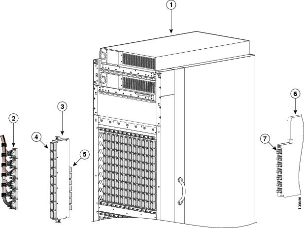
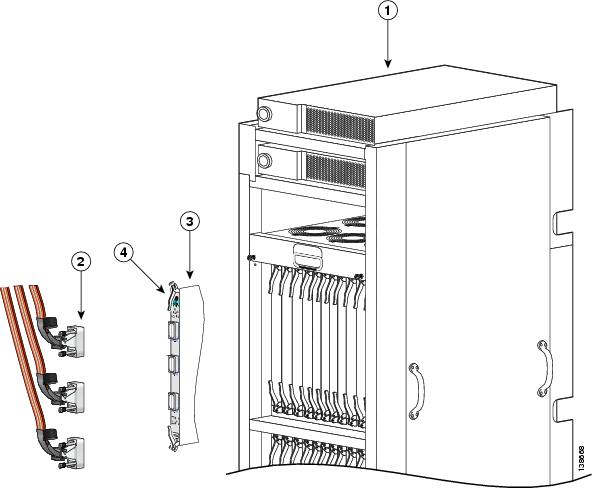
Figure 1-1 shows the fiber-optic connections in an FCC. Figure 1-2 shows the fiber-optic connections in an LCC.
Figure 1-1 Fiber-Optic Connections in an FCC (Rear View of Chassis)F
|
|
Fabric card chassis |
|
Optical interface module (OIM) |
|
OIM HBMT connectors |
|
S2 HBMT connectors |
|
|
Optical array cable connectors |
|
OIM bulkhead array connectors |
|
S2 switch fabric card (SFC) |
Figure 1-2 Fiber-Optic Connections in an LCC (Rear View of Chassis)
|
|
Line card chassis |
|
S13 fabric card (FC/M) |
|
|
Optical array cable connectors |
|
S13 bulkhead array adapters |
About the Cisco CRS-1 Fiber-Optic Cleaning Kit
All optical connections in a multishelf system are cleaned using the Cisco CRS-1 fiber-optic cleaning kit. This kit includes a tool that advances a lint-free cloth across the optical surface to remove any contaminants. The cleaning kit also includes an adapter for each connector type. The adapter ensures that the cleaning tool is inserted at the correct angle and depth for cleaning.
This section presents the following topics:
•![]() Description of the Fujikura IBC Cleaning Tool
Description of the Fujikura IBC Cleaning Tool
Contents of the Cleaning Kit
The Cisco CRS-1 fiber-optic cleaning kit includes the following items:
•![]() Fujikura IBC (in bulkhead cleaner) cleaning tool (see Figure 1-3)
Fujikura IBC (in bulkhead cleaner) cleaning tool (see Figure 1-3)
•![]() OIM/S13 array adapter (see Figure 1-4)
OIM/S13 array adapter (see Figure 1-4)
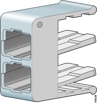
•![]() S2 HBMT adapter (see Figure 1-5)
S2 HBMT adapter (see Figure 1-5)
•![]() OIM HBMT adapter (see Figure 1-6)
OIM HBMT adapter (see Figure 1-6)
Figure 1-3 Fujikura IBC Cleaning Tool and Clear Protective Cap
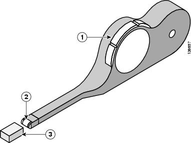
Figure 1-4 OIM/S13 Array Adapter
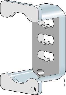
Figure 1-5 S2 HBMT Adapter
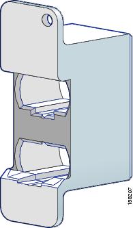
Figure 1-6 OIM HBMT Adapter
Description of the Fujikura IBC Cleaning Tool
Use the Fujikura IBC cleaning tool (see Figure 1-7) to clean the ferrules of your fiber optic connectors.

Note ![]() Be sure to replace the protective cap after each use of the cleaning tool.
Be sure to replace the protective cap after each use of the cleaning tool.
Figure 1-7 Fujikura IBC Cleaning Tool and Clear Protective Cap
|
|
Thumb wheel |
|
Protective cap |
|
|
Cleaning head |
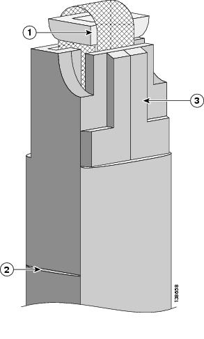
Use the thumb wheel of the cleaning tool to advance the cleaning surface (see Figure 1-8) after cleaning each ferrule so as to ensure a clean section for the next ferrule. The cleaning tool includes an alignment edge and key to help you properly align it with the optical interface surfaces during cleaning.
Figure 1-8 Fujikura IBC Cleaning Tool Head and Alignment Edge
|
|
Cleaning head |
|
Key |
|
|
Alignment edge |
Using the Fujikura IBC Cleaning Tool
To operate the cleaning tool, complete the following steps for each ferrule:
Step 1 ![]() Attach an ESD-preventive wrist strap to your wrist and connect its leash to an ESD connection socket or a bare metal surface on the chassis.
Attach an ESD-preventive wrist strap to your wrist and connect its leash to an ESD connection socket or a bare metal surface on the chassis.
Step 2 ![]() Place the proper adapter over the ferrule, as described in this guide. Each type of connector uses a different adapter. The adapter ensures that the cleaning tool is inserted at the correct angle and depth for cleaning.
Place the proper adapter over the ferrule, as described in this guide. Each type of connector uses a different adapter. The adapter ensures that the cleaning tool is inserted at the correct angle and depth for cleaning.
Step 3 ![]() Insert the cleaning head into the adapter so that the cleaning surface sits flush against the ferrule. Align the key with the matching notch in the adapter slot.
Insert the cleaning head into the adapter so that the cleaning surface sits flush against the ferrule. Align the key with the matching notch in the adapter slot.
Step 4 ![]() To clean the surface, advance the white thumb wheel until you hear two hard clicks. This action moves a continuous roll of lint-free cleaning cloth across the surface of the fibers, removing dust and other contaminants. The cleaning tool holds enough cloth to clean well over 100 ferrules.
To clean the surface, advance the white thumb wheel until you hear two hard clicks. This action moves a continuous roll of lint-free cleaning cloth across the surface of the fibers, removing dust and other contaminants. The cleaning tool holds enough cloth to clean well over 100 ferrules.
Note ![]() The thumb wheel makes a series of soft clicks followed by a "hard click" when turned. The hard click is represented by six large notches along the edge of the thumb wheel. Always advance the thumb wheel until you hear two hard clicks.
The thumb wheel makes a series of soft clicks followed by a "hard click" when turned. The hard click is represented by six large notches along the edge of the thumb wheel. Always advance the thumb wheel until you hear two hard clicks.
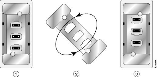
Step 5 ![]() Rotate the adapter 180 degrees to clean the remaining ferrules, as shown in Figure 1-9.
Rotate the adapter 180 degrees to clean the remaining ferrules, as shown in Figure 1-9.
Figure 1-9 Rotating the Adapter 180 Degrees to Clean All Ferrules
|
|
Install the adapter and clean the first set of ferrules. |
|
Install the adapter and clean the remaining ferrules. |
|
|
Rotate the adapter 180 degrees. |
 Feedback