Information About Air Circulation Components
This section describes the air circulation components: the fan trays and the air filters.
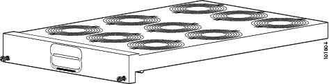
The LCC has two fan trays (show in the figure below), one just below the lower card cage and the other just above the upper card cage. The chassis can run with only one fan tray operating. If a failure occurs in one fan tray, the other fan tray acts as the redundant fan tray to assure fault-tolerant system performance; the chassis continues to operate while the failed fan tray is replaced.
The LCC fan tray operates in either the upper or lower fan tray slots. Each fan tray installs into the rear (MSC) side of the chassis and contains:
- Nine fans
- Fan tray board
- Front-panel status LED
 Note |
The upper and lower fan trays are interchangeable and installed in the same manner. |

|
1 |
Front (PLIM) side of chassis |
6 |
Power shelves (two installed) |
|
2 |
Air intake |
7 |
Air exhaust |
|
3 |
Lower fan tray |
8 |
Upper card cage |
|
4 |
Air filter |
9 |
Lower card cage |
|
5 |
Upper fan tray |
10 |
Rear [MSC] side of chassis |
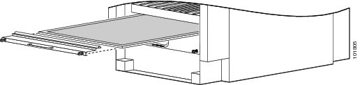
The chassis has a serviceable air filter mounted in a slide-out tray accessible from the front of the chassis just below the lower card cage (as shown in the figure). The air filter removes dust from the room air drawn into the router by the two fan trays. Once a month (or more often in dusty environments) you should examine the air filter and replace it if it appears damaged or excessively dirty.

 Feedback