Configuring Connected Grid Swap Drive and Cisco IOS IPS on the CGR 2010 Router
Available Languages
Table Of Contents
Cisco Connected Grid 2010 Router Software Configuration Guide, Cisco IOS Release 15.2(2)T
Connected Grid Swap Drive Overview
Router Compact Flash Memory Cards
Using the Connected Grid Swap Drive Feature
Enable the Connected Grid Swap Drive Feature
Save Source Router Configuration to the Flash Memory Card
Transfer the Configuration to the New Router
Verify the Configuration on the New Router
Cisco IOS Intrusion Protection System (IPS)
Supported IPS Signatures for the Cisco CGR 2010
Related Documents and Online Tools
Cisco Connected Grid 2010 Router Software Configuration Guide, Cisco IOS Release 15.2(2)T
Publication Date: November 15, 2011Part Number: OL-26207-01
Cisco IOS Release: Cisco IOS Release 15.2(2)T
This guide describes how to configure the Cisco IOS Release 15.2(2)T features described in Supported Products on the Cisco Connected Grid 2010 Router (Cisco CGR 2010). Use this document in conjunction with other router software configuration documentation.

Note
This document provides information about platform-specific features for Cisco IOS Release 15.2(2)T for the Cisco CGR 2010. For cross-platform information for the router, including new features, resolved caveats, and open caveats, refer to the 15.1M&T cross-platform release notes, at: http://www.cisco.com/en/US/products/ps10977/prod_release_notes_list.html
This document contains the following sections:
•
•
Tell Us What You Think
Supported Products
Connected Grid Swap Drive
Cisco CGR 2010
Cisco IOS Release 15.2(2)T
Cisco IOS IPS
Cisco CGR 2010
Cisco IOS Release 15.2(2)T
Connected Grid Swap Drive
This section describes the Connected Grid Swap Drive feature for the router and includes the following topics:
•
•
Connected Grid Swap Drive Overview
Using the Connected Grid Swap Drive feature, you can transfer system configuration information from one router to another using a compact flash memory card (or compact flash card) while the routers are operating. This functionality enables you to quickly configure new routers with a standard configuration with little or no manual configuration required.
During normal operation, the router configuration information is stored on the router internal bootflash memory. When the Connected Grid Swap Drive feature is enabled, however, configuration information is saved to the bootflash and to the router compact flash memory card. After saving the router configuration to the compact flash card, you can insert the card into another router. When the new router is rebooted, it uses the configuration from the compact flash card as the running and startup configuration.
You can use this configuration method for:
•
•
Required ROM Monitor Version
This feature requires that the router is using ROM monitor (ROMmon) version 15.0(1r)M13 or later. The ROMmon is sometimes referred to as the bootstrap program. For more information on using ROMmon with the router, refer to the "Using ROM Monitor" chapter in the router configuration guide at:
http://www.cisco.com/en/US/docs/routers/access/2000/CGR2010/software/configuration/guide/rommon.html
Check ROMmon Version
Enter the show rom-monitor slot privileged EXEC command to verify the version of ROMmon that is running on the router:
Router# show rom-monitor slotSystem Bootstrap, Version 15.0(1r)M13, RELEASE SOFTWARE (fc1)Copyright (c) 2011 by Cisco Systems, Inc.Upgrade ROMmon Version
Use the upgrade rom-monitor privileged EXEC command to upgrade router ROMmon as needed to use the Connected Grid Swap Drive feature.
Refer to the Cisco IOS Configuration Fundamentals Command Reference for detailed information about using this command:
http://www.cisco.com/en/US/docs/ios/fundamentals/command/reference/cf_t1.html#wp1060450
Router Compact Flash Memory Cards
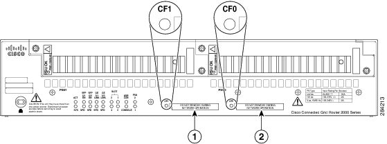
The router supports a maximum of two compact flash memory cards. The router ships with one compact flash card installed and supports a second, optional flash card that you can order with the router or supply separately. Figure 1 illustrates the location of the compact flash card slots on the router.
Figure 1 Cisco Connected Grid 2010 Router—Compact Flash Memory Card Slot Locations
For additional information about the router compact flash memory support, refer to the router hardware installation guide at:
http://www.cisco.com/en/US/products/ps10977/prod_installation_guides_list.html
Using the Connected Grid Swap Drive Feature
Note
These are the major steps, described in more detail in this section:
1.
2.
3.
4.
Enable the Connected Grid Swap Drive Feature
The Connected Grid Swap Drive feature is disabled by default on the router. When this feature is disabled, the write memory command saves the router running configuration to the router system bootflash only (default write memory behavior). When the Connected Grid Swap Drive feature is enabled, the write memory command saves the router running configuration to both the router system bootflash and to the router compact flash card installed in slot CF0 (see Figure 1).
Enable the feature with the swap-drive global configuration command:
CGR2010(config)# swap-drive
Note
Disable the feature using the no form of the command:
CGR2010(config)# no swap-driveSave Source Router Configuration to the Flash Memory Card
Follow these steps while the source router is operating normally to save the running configuration to the compact flash card.
Step 1
CGR2010> write memoryThis command creates two text files on the compact flash card:
•
•
Note
Step 2
CGR2010# dir flash:Directory of flash0:1 -rw- 63822856 Oct 13 2011 21:22:58 cgr2010-universalk9-mz.SPA.152-1.14.T0.22 -rw- 1181 Oct 26 2011 17:26:50 system_swap_drive_config.txt3 -rw- 50865812 Jul 18 2011 18:34:28 cgr2010-universalk9-mz.SPA.151-3.T1.bin4 -rw- 57747592 Aug 24 2011 21:01:32 cgr2010-universalk0-mz.SSA-swapdr5-25 -rw- 87 Oct 26 2011 17:26:50 system_boot_config_txtStep 3
Transfer the Configuration to the New Router
Follow these steps to transfer the saved configuration files to the new router. This procedure can be performed when the router is off or while the router is operating normally.
Step 1
Step 2
When the router boots up, the ROM monitor software verifies that:
•
•
When the router detects the swap_drive_config.txt file on flash0, the following steps take place:
•
•
Additional Information
•
•
Verify the Configuration on the New Router
Follow these steps to verify that the configuration from the source router has been successfully transferred to the new router:
Step 1
CGR2010# show running-configStep 2
CGR2010# show startup-configCommand Syntax Summary
This section summarizes the command syntax used with the Connected Grid Swap Drive feature.
swap-drive
The swap-drive global configuration command enables the Connected Grid Swap Drive feature.
Use the no form of the command to disable the Connected Grid Swap Drive feature.
swap-drive
The swap-drive global configuration command enables the Connected Grid Swap Drive feature on the router. The default setting is disabled.
When this feature is enabled, enter the write memory command to save the router running configuration to both the router system boot flash and the router compact flash card installed in slot CF0 (see Figure 1). This enables you to transfer configuration between routers using the compact flash card.
Cisco IOS Intrusion Protection System (IPS)
This section describes the Cisco IOS IPS feature for the router and includes the following topics:
About Cisco IOS IPS
Cisco IOS IPS technology enhances perimeter firewall protection by taking appropriate action on packets and flows that violate the security policy or represent malicious network activity.
Cisco IOS IPS identifies attacks using "signatures" to detect patterns of misuse in network traffic. Cisco IOS IPS acts as an in-line intrusion detection sensor, watching packets and sessions as they flow through the router, scanning each to match currently active (loaded) attack signatures. When Cisco IOS IPS detects suspicious activity, it responds before network security can be compromised, it logs the event, and, depending on the action(s) configured to be taken for the detected signature(s), it does one of the following:
•
•
•
•
•
Configuring Cisco IOS IPS
For detailed instruction on configuring Cisco IOS IPS on the router, refer to the chapter "Configuring Cisco IOS Intrusion Prevention System (IPS)" in the Security Configuration Guide: Securing the Data Plane, Cisco IOS Release 15.1M&T at:
Supported IPS Signatures for the Cisco CGR 2010
This section lists the SCADA signatures that the router supports in Cisco IOS Release 15.2(2)T and later. Click the signature name in the Name column to go to the detailed entry for the signature on the Cisco Security Intelligence Operations web site.
Related Documents and Online Tools
These documents contains additional software configuration information for the Cisco Connected Grid 2010 Router:
•
http://www.cisco.com/en/US/products/ps10977/prod_installation_guides_list.html
•
http://www.cisco.com/en/US/products/ps10977/products_installation_and_configuration_guides_list.html
•
http://www.cisco.com/en/US/docs/ios/fundamentals/command/reference/cf_book.html
•
http://www.cisco.com/en/US/products/ps10977/prod_release_notes_list.html
•
http://tools.cisco.com/security/center/search.x?search=Signature
Technical Assistance
Finding Support Information for Platforms and Cisco IOS Software Images
Use Cisco Feature Navigator to find information about platform support and Cisco IOS software image support. Access Cisco Feature Navigator at http://www.cisco.com/go/fn. You must have an account on Cisco.com. If you do not have an account or have forgotten your username or password, click Cancel at the login dialog box and follow the instructions that appear.
Technical Assistance Center Home Page
The Technical Assistance Center (TAC) home page contains 30,000 pages of searchable technical content, including links to products, technologies, solutions, technical tips, and tools. Registered Cisco.com users can log in from this page to access even more content.
http://www.cisco.com/public/support/tac/home.shtml
This document is to be used in conjunction with the documents listed in the "Related Documents and Online Tools" section.
Cisco and the Cisco logo are trademarks or registered trademarks of Cisco and/or its affiliates in the U.S. and other countries. To view a list of Cisco trademarks, go to this URL: www.cisco.com/go/trademarks. Third-party trademarks mentioned are the property of their respective owners. The use of the word partner does not imply a partnership relationship between Cisco and any other company. (1110R)
© 2011 Cisco Systems, Inc. All rights reserved.

 Feedback
Contact Cisco
- Open a Support Case

- (Requires a Cisco Service Contract)