
Table Of Contents
Installing the Cisco ASR 9000 Series Router
Pre-Installation Considerations and Requirements
Unpacking the Cisco ASR 9010 Router
Unpacking the Cisco ASR 9006 Router
Removing Components Before Installing the Chassis
Removing Cards from the Chassis
Removing RSP and Line Cards from the Chassis
Rack-Mounting the Router Chassis
Installing the Chassis in a Two-Post Rack
Installing the Chassis in a Four-post Rack
Supplemental Bonding and Grounding Connections
Installing Chassis Accessories
Installing Chassis Accessories on the Cisco ASR 9010 Router
Installing Chassis Accessories on the Cisco ASR 9006 Router
Reinstalling Components After Installing the Chassis
Reinstalling Cards in the Chassis
Reinstalling RSP Cards in the Chassis
Reinstalling Line Cards in the Chassis
Connecting Line Card Network Interface Cables
Connecting RSP Route Processor Cables
Connecting to the RSP Console Port
Connecting to the RSP Auxiliary Port
Connecting to the RSP Ethernet Management Ports
Connecting Power to the Router
Connecting Power to an AC-Powered Router
Connecting Power to a DC-Powered Router
Installing the Cisco ASR 9000 Series Router
This chapter contains the procedures to install the router in a rack. The installation is presented in the following sections:
•
Pre-Installation Considerations and Requirements
•
•
•
•
•
•
•
•
•
•
Pre-Installation Considerations and Requirements
Before you perform any procedures in this chapter, review the following sections:
•
In particular, observe the guidelines for preventing electrostatic discharge (ESD) damage described in the "Preventing Electrostatic Discharge Damage" section on page 1-2. Use Figure 1-1 on page 1-3 or Figure 1-2 on page 1-4 as a reference in locating and using the ESD sockets on the front of the router chassis.
For additional safety and compliance information, refer to the Regulatory Compliance and Safety Information for the Cisco ASR 9000 Series Aggregation Services Routers publication that accompanied your router.

Warning
Installation Overview
The router is shipped strapped to a shipping pallet as shown in Figure 2-1.
Figure 2-1 Cisco ASR 9010 Router Packaged on Shipping Pallet
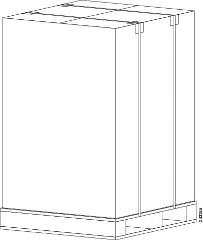
A fully equipped router with six power modules can weigh as much as 375 pounds (170.5 kg); an empty chassis weighs 150 pounds (67.8 kg). The chassis is designed to be lifted by two persons after you remove some of the components, such as line cards, power supplies, and the fan tray, to reduce the weight before lifting the chassis. See the "Removing Components Before Installing the Chassis" section for procedures to remove these components.
Required Tools and Equipment
Before you begin the rack-mount installation, you must read and understand the information in the "Rack-Mounting Guidelines" section on page 1-9 and have the following tools and equipment:
•
•
•
•
•
•
•
•
Unpacking the Router
Unpacking the Cisco ASR 9010 Router
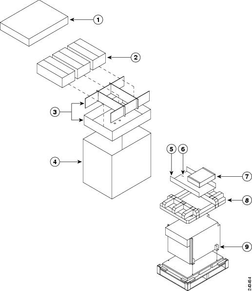
Use the follow unpacking instructions to unpack the router from its shipping container (Figure 2-2).
Step 1
Step 2
Step 3
a.
b.
Step 4
Figure 2-2 Unpacking the Cisco ASR 9010 Router from the Shipping Container and Pallet
Step 5
Step 6
Unpacking the Cisco ASR 9006 Router
Use the follow unpacking instructions to unpack the router from its shipping container (Figure 2-3).
Step 1
Step 2
Step 3
a.
b.
c.
Step 4
Step 5
Figure 2-3 Unpacking the Cisco ASR 9006 Router from the Shipping Container and Pallet
Positioning the Router
Use a safety hand truck to move the router to the location where it is being installed in a rack.
Removing Components Before Installing the Chassis
The Cisco ASR 9000 Series Routers are designed to be lifted by two persons into a rack. To reduce the weight of the system, you must remove some of the components before attempting to lift it into the rack.
Removing Power Modules
The power supply modules for the Cisco ASR 9000 Series Routers are shipped separately. If you need to remove an AC or DC power module at a later time, see the "Removing and Replacing an AC or DC Power Module" section on page 4-5.
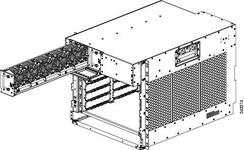
Removing the Fan Tray
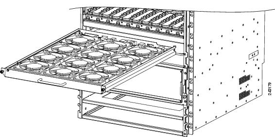
By removing the fan tray from the chassis, you can reduce the weight of the chassis by approximately 13.82 pounds (6.27 kg).
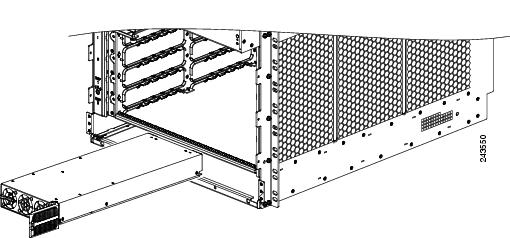
Use the following procedure to remove the fan tray from the Cisco ASR 9010 Router chassis (Figure 2-4).

Note
Step 1
Step 2
Step 3
Warning
Figure 2-4 Removing or Installing the Fan Tray on the Cisco ASR 9010 Router Chassis
Use the following procedure to remove the fan tray(s) from the Cisco ASR 9006 Router chassis (Figure 2-5).
Step 1
Step 2
Step 3
Step 4
Warning
Figure 2-5 Removing or Installing the Fan Tray on the Cisco ASR 9006 Router Chassis
Removing Cards from the Chassis
To reduce additional weight from the chassis, you can remove all Route Switch Processor (RSP) and line cards. This section describes how to remove the various types of cards.
Removing RSP and Line Cards from the Chassis
The Cisco ASR 9010 Router chassis contains 10 slots (Figure 2-6). The RSP cards are installed in the two center slots (labeled RSP0 and RSP1). Four line cards are installed in slots 0 through 3 to the left of the RSP card slots and four line cards are installed in slots 4 through 7 to the right of the RSP card slots.
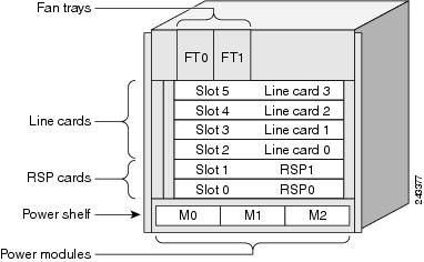
The Cisco ASR 9006 Router chassis contains 6slots (Figure 2-7). The RSP cards are installed in the two lowest slots (labeled RSP0 and RSP1) above the power modules. Four line cards are installed in slots 2 through 5 above the RSP card slots.

Caution
Caution
Caution
Figure 2-6 Cisco ASR 9010 Router Components and Slot Numbering
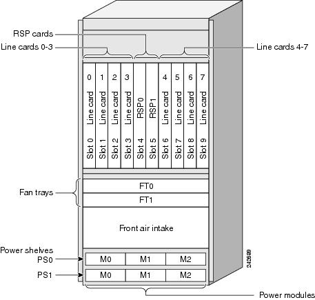
Figure 2-7 Cisco ASR 9006 Router Components and Slot Numbering
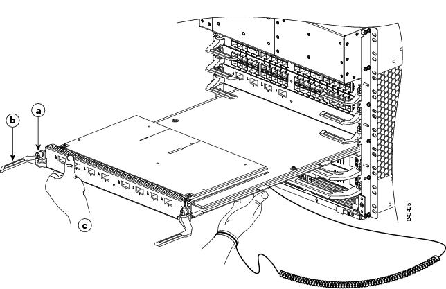
Use the following procedure to remove RSP and line cards from the chassis.
Step 1
Step 2
a.
b.
c.
Figure 2-8 Removing a Line Card from the Cisco ASR 9010 Router Chassis
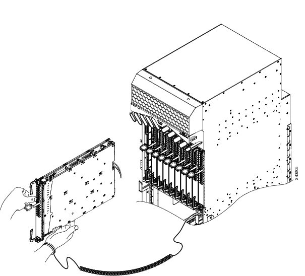
Figure 2-9 Removing a Line Card from the Cisco ASR 9006 Router Chassis
Step 3
Rack-Mounting the Router Chassis
The router chassis is installed in a front-mounted position, as shown in Figure 1-6 for the Cisco ASR 9010 Router chassis and Figure 1-7 for the Cisco ASR 9006 Router chassis)..
In a front-mounted position, the chassis rack-mounting flanges are secured directly to the rack posts.
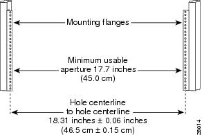
Verifying Rack Dimensions
Before you install the chassis, measure the space between the vertical mounting flanges (rails) on your equipment rack to verify that the rack conforms to the measurements shown in Figure 2-10.
Step 1
The distance should measure 18.31 inches ± 0.06 inches (46.5 cm ± 0.15 cm).
Note
Step 2
The space must be at least 17.7 inches (45 cm) to accommodate the chassis, which is approximately 17.50 in. (44.45 cm) wide and fits between the mounting posts on the rack.
Figure 2-10 Verifying Equipment Rack Dimensions
Installing the Chassis in a Two-Post Rack
Two people can lift an empty router chassis using the handles on the sides. To accommodate racks with different hole patterns in their mounting flanges, the chassis rack-mounting flanges have three groups of eight oblong screw holes on each side.
This section describes how to install the chassis in a two-post telco-style rack.
Figure 2-11 shows the orientation of the Cisco ASR 9010 Router chassis to the rack posts and components used in the installation. To mount the Cisco ASR 9010 Router chassis in a two-post open rack, two side mounting brackets must be attached to the chassis and the front posts of the rack.
Figure 2-12 shows the orientation of the Cisco ASR 9006 Router chassis to the rack posts and components used in the installation.
Figure 2-11 Installing the Cisco ASR 9010 Router Chassis in a Two-Post Rack
Warning
Figure 2-12 Installing the Cisco ASR 9006 Router Chassis in a Two-Post Rack
Use the following procedure to install the chassis in the equipment rack:
Step 1
Figure 2-13 Correct Lifting Positions
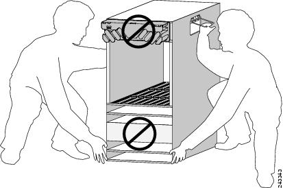
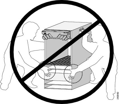
Caution
Figure 2-14 Incorrect Lifting Handholds
Step 2
Step 3
Step 4
Step 5
Step 6
Step 7
Step 8
Step 9
Installing the Chassis in a Four-post Rack
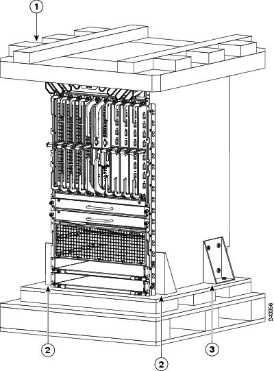
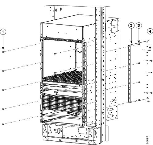
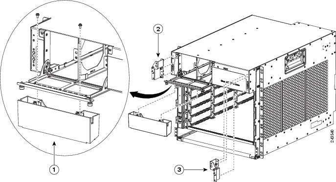
To mount the Cisco ASR 9010 Router chassis in a four-post open rack, two side brackets must be attached to the chassis and the rear posts (Figure 2-15).
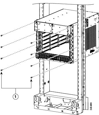
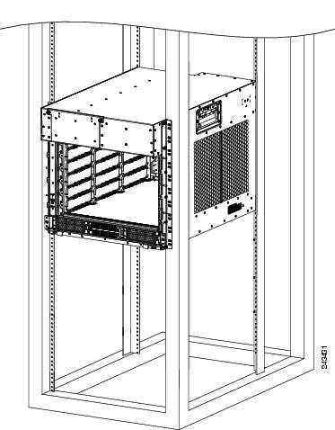
The Cisco ASR 9006 Router is installed in a four-post open rack without using extra brackets (Figure 2-16).
Figure 2-15 Installing the Cisco ASR 9010 Router Chassis in a Four-Post Rack
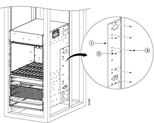
1
Rear mounting bracket.
2
Five screws (minimum) to attach the rear mounting bracket to the rear post of the rack.
3
Five screws (minimum) to attach the rear mounting bracket to the router chassis.
Figure 2-16 Installing the Cisco ASR 9006 Router Chassis in a Four-Post Rack
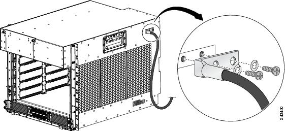
Supplemental Bonding and Grounding Connections
Before you connect power to the router, or power on the router for the first time, we recommend that you connect the central office ground system or New Equipment Building System (NEBS) to the threaded supplemental bonding and grounding receptacles on the router. For more information on supplemental bonding and grounding cable requirements, see the "NEBS Supplemental Unit Bonding and Grounding Guidelines" section on page 1-24.
Use the following procedure to attach a grounding cable lug to the router:
Step 1
Step 2
Step 3
Figure 2-17 NEBS Bonding and Grounding for the Cisco ASR 9010 Router
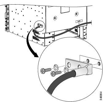
Figure 2-18 NEBS Bonding and Grounding for the Cisco ASR 9006 Router
Installing Chassis Accessories
The Cisco ASR 9000 Series Routers come with a base set of chassis accessories. To install the base chassis accessories, use the appropriate procedure below for your router.
Installing Chassis Accessories on the Cisco ASR 9010 Router
To install the supplied base chassis accessories on the Cisco ASR 9010 Router, perform the following steps:
Step 1
Figure 2-19 Installing Ball Studs on the Cisco ASR 9010 Router for Mounting Chassis Accessories
Step 2
Step 3
Note
Figure 2-20 Installing Chassis Accessories on the Cisco ASR 9010 Router
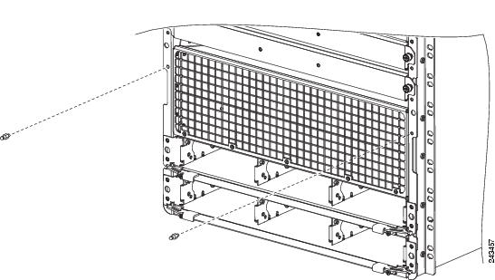
Installing Chassis Accessories on the Cisco ASR 9006 Router
To install the supplied base chassis accessories on the Cisco ASR 9006 Router, perform the following steps:
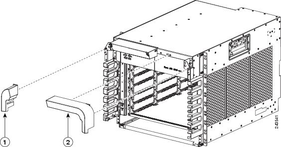
Step 1
Step 2
Figure 2-21 Installing Fan Tray Door Accessory and Accessory Mounting Brackets on the Cisco ASR 9006 Router
1
Plastic fan tray door accessory.
2
Metal bracket for mounting plastic accessory on left upper corner of chassis..
3
Metal bracket for mounting plastic accessory on right upper corner of chassis..
Step 3
Step 4
Step 5
Step 6
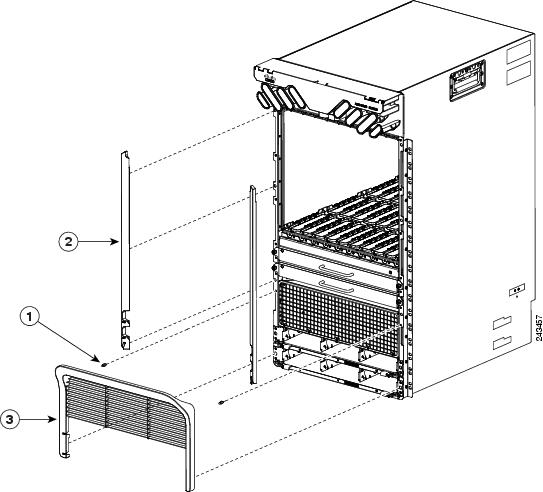
Figure 2-22 Installing Front Panel Plastic Chassis Accessories on the Cisco ASR 9006 Router
1
Plastic chassis accessory attaches to metal bracket at upper left corner of chassis.
2
Plastic chassis accessory attaches to metal bracket at upper right corner of chassis.
Step 7
Figure 2-23 Installing Chassis Cable Management Brackets on the Cisco ASR 9006 Router
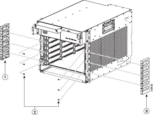
1
Left side cable management bracket.
2
Six screws for attaching the cable management brackets (three per side).
3
Right side cable management bracket.
Reinstalling Components After Installing the Chassis
This section describes how to reinstall the components that you removed before installing the chassis in the rack. It also describes how to reconnect cables to line cards, the RSP, and alarm cards. In most cases, the procedure s for the Cisco ASR 9006 Router are identical to those for the Cisco ASR 9010 Router, unless noted otherwise.
Installing Power Modules
The following procedures describe how to reinstall the AC power modules back into the chassis. Be sure to follow the correct procedure for the type of power modules that you have.
Caution
Installing AC Power Modules
Use the following procedure to reinstall the AC power modules back into the chassis (see Figure 2-24 for the Cisco ASR 9010 Router or Figure 2-25 for the Cisco ASR 9006 Router).
Step 1
Step 2
Caution
Step 3
Step 4
Figure 2-24 Installing an AC or DC Power Module in the Cisco ASR 9010 Router
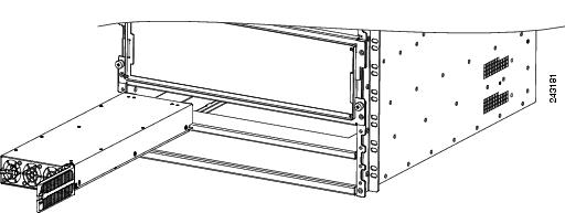
Figure 2-25 Installing an AC or DC Power Module in the Cisco ASR 9006 Router
Installing DC Power Modules
Use the following procedure to reinstall the DC power modules back into the chassis (see Figure 2-24 for the Cisco ASR 9010 Router or Figure 2-25 for the Cisco ASR 9006 Router).
Step 1
Step 2
Caution
Step 3
Step 4
Reinstalling the Fan Trays
Use the following procedure to reinstall the fan trays in the chassis (Figure 2-4 and Figure 2-5).
Note
Step 1
Step 2
Caution
Step 3
Step 4
Note
Step 5
Reinstalling Cards in the Chassis
This section describes how to reinstall various line cards back into the chassis.
Caution
Caution
Caution
Caution
Caution
Caution
Reinstalling RSP Cards in the Chassis
Use the following procedure to reinstall RSP cards into the chassis (see Figure 2-6 and Figure 2-7 for slot numbering).
Step 1
Step 2
Caution
Some flexing in the backplane is normal. When you push the ejector levers fully vertical, the card is seated in the backplane connectors. However, when you release the levers, backplane flexing pushes the levers out, so the levers may be slightly loose. Tightening the captive installation screws prevents any additional movement from flexing of the backplane.
Step 3
Note
Step 4
Note
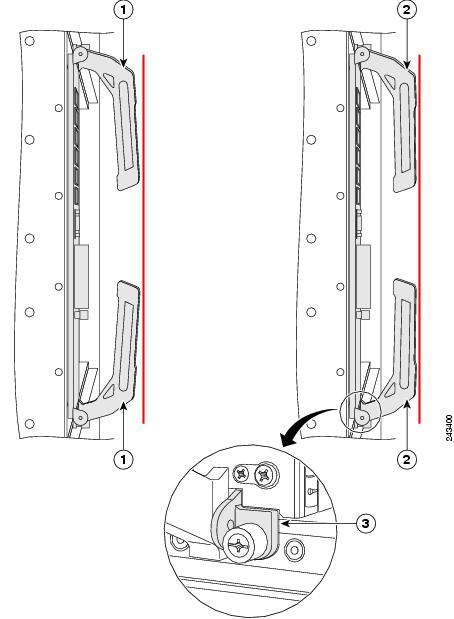
Figure 2-26 RSP Card Ejector Lever Positions During Installation
Reinstalling Line Cards in the Chassis
Before you begin reinstalling cards in the card cage, identify slot assignments by referring to the written list you prepared when you removed the cards (refer to Figure 2-6 and Figure 2-7 for slot numbering).
Caution
Use the following procedure to reinstall line cards in the chassis card cage.
Step 1
Step 2
Step 3
Note
Figure 2-27 Installing a Line Card into the Cisco ASR 9010 Router Chassis
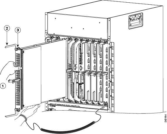
Figure 2-28 Installing a Line Card into the Cisco ASR 9006 Router Chassis
Step 4
Step 5
Connecting Line Card Network Interface Cables
This section describes how to route the network interface cables through the router cable-management system and attach the network interface cables to the line card ports.
This procedure uses an 40x1GE line card as an example to describe how to attach a network interface cable to a line card port and route the cable through the cable-management system. Depending on which line cards are installed in your system, your cable connection procedure might differ slightly from this example. For cable connection information for your specific line card, refer to the installation and configuration note for that line card.
Note
Use the following procedure as an example to route the network interface cables through the cable-management system and connect them to the line card.
Step 1
Note
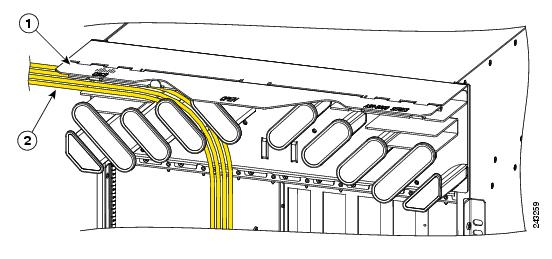
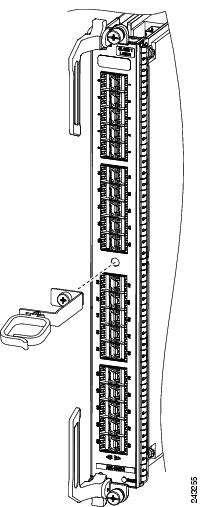
Figure 2-29 Routing Interface Cables through the Cable Management Tray
Step 2
Step 3
Step 4
Step 5
Figure 2-30 Attaching a Line Card Cable Management Bracket
Caution
Figure 2-31 Example of Interface Cable Routing Using Line Card Cable Management Brackets on the Cisco ASR 9010 Router
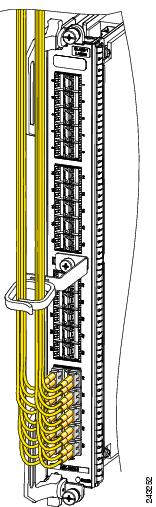
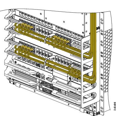
Figure 2-32 Example of Interface Cable Routing Using Line Card and Chassis Cable Management Brackets on the Cisco ASR 9006 Router
Connecting RSP Route Processor Cables
This section describes how to connect cables to the console, auxiliary, and Ethernet ports on the RSP. The console and auxiliary ports are both asynchronous serial ports; any devices connected to these ports must be capable of asynchronous transmission. For example, most modems are asynchronous devices.
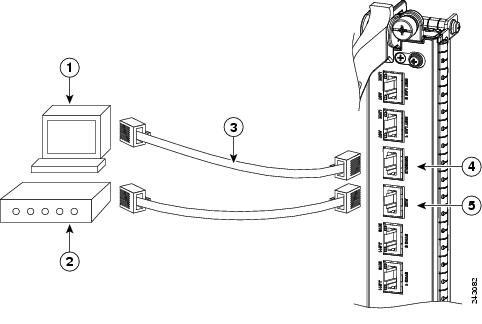
Figure 2-33 shows an example of a data terminal and modem connections.
Figure 2-33 RSP Console and Auxiliary Port Connections
Caution
Note
Note
Connecting to the RSP Console Port
The system console port on the RSP is an RJ-45 receptacle for connecting a data terminal to perform the initial configuration of the router. The console port requires a straight-through RJ-45 cable.
See the "RSP Port Connection Guidelines" section on page 1-25 for additional information about the console port.
Refer to Figure 2-33 and use the following procedure to connect a data terminal to the RSP console port.
Step 1
Step 2
Step 3
Step 4
Step 5
Connecting to the RSP Auxiliary Port
The auxiliary port on the RSP is a RJ-45 receptacle for connecting a modem or other data communication equipment (DCE) device (such as another router) to the RSP. The asynchronous auxiliary port supports hardware flow control and modem control.
See the "RSP Port Connection Guidelines" section on page 1-25 for additional information about the auxiliary port.
Refer to Figure 2-33 and use the following procedure to connect an asynchronous serial device to the RSP auxiliary port.
Step 1
Step 2
Step 3
Step 4
Connecting to the RSP Ethernet Management Ports
To connect cables to the RSP management ports, attach Category 5 UTP cables directly to the MGT LAN 0 and MGT LAN 1 RJ-45 receptacles on the RSP.
See the "Management LAN Ports" section on page 1-27 for additional information about the Ethernet management LAN ports.
Note
Caution
.Use the following procedure to connect an Ethernet cable to the RSP RJ-45 Ethernet receptacle:
Step 1
Step 2
Note
Connecting the Alarm Cable
The router alarm connector, located on the RSP front panel, is a 9-pin D-subconnector, labeled Alarm Out (Figure 2-34).
Figure 2-34 Alarm Out Cable Connector
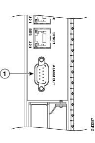
The alarm subconnector can be used to connect the router to an external site alarm maintenance system. Any critical, major, and minor alarms generated by the router also energize alarm relays on the alarm card and activate the external site alarm. The alarm relay contacts on the RSP card consist of standard common, normally open, and normally closed relay contacts that are wired to the Alarm Out connector pins.
Table 1-5 on page 1-30 lists the pin-to-signal correspondence between the connector pins and the alarm relay contacts. Because alarm contact cables are entirely dependent on installation site circumstances, alarm connector cables are not available from Cisco. For information about alarm connector wiring requirements and the pinouts for the alarm connector interface, see the "Alarm Connection Guidelines" section on page 1-29.
Caution
Note
Connecting Power to the Router
Use the one of the following procedures to connect power to your router.
•
•
Caution
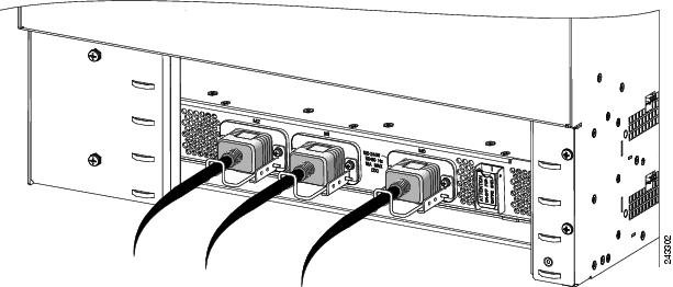
Connecting Power to an AC-Powered Router
Use the following procedure to connect the AC power cords to the router.
Note
Step 1
Step 2
Step 3
Warning
Step 4
Step 5
Figure 2-35 Typical AC Power Connections to an AC Power Shelf
Step 6
Step 7
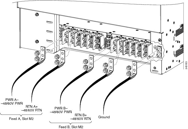
Connecting Power to a DC-Powered Router
This section contains the procedures to connect the DC source power cables to a DC-powered router.
The color coding of source DC power cable leads depends on the color coding of the site DC power source. Because there is no color code standard for source DC wiring, you must be sure that power source cables are connected to the power module with the proper positive (+) and negative (-) polarity:
•
•
Caution
Note
Warning
Use the following procedure to connect the DC source power cables to a DC power shelf.
Step 1
Step 2
Step 3
a.
b.
c.
d.
Warning
Step 4
Figure 2-36 Typical DC Power Connections to a Power Shelf with a Single DC Power Module Installed in Slot M2
Step 5
Powering on the Router
Use the following procedure to turn on power to either an AC-powered or DC-powered router:
Step 1
Step 2
Step 3
Step 4