Cisco VG224 Voice Gateway Hardware Installation Guide
Bias-Free Language
The documentation set for this product strives to use bias-free language. For the purposes of this documentation set, bias-free is defined as language that does not imply discrimination based on age, disability, gender, racial identity, ethnic identity, sexual orientation, socioeconomic status, and intersectionality. Exceptions may be present in the documentation due to language that is hardcoded in the user interfaces of the product software, language used based on RFP documentation, or language that is used by a referenced third-party product. Learn more about how Cisco is using Inclusive Language.
- Updated:
- October 11, 2004
Chapter: Planning Your Installation
Planning Your Installation
Before you install your Cisco VG224 voice gateway, consider the information in this chapter:
•![]() Location and Mounting Requirements
Location and Mounting Requirements
•![]() Distance Limitations for Interface Cables
Distance Limitations for Interface Cables
Location and Mounting Requirements
The three mounting possibilities for your Cisco VG224 voice gateway are as follows:
•![]() Rack-mount
Rack-mount
•![]() Wall-mount
Wall-mount
•![]() Bench-top
Bench-top
The mounting location must provide the following:
•![]() Access to the chassis
Access to the chassis
•![]() Access to a suitable power source
Access to a suitable power source
•![]() Access to an appropriate earth ground
Access to an appropriate earth ground
•![]() Allowance for adequate heat dissipation and airflow around the chassis
Allowance for adequate heat dissipation and airflow around the chassis
Temperature Control and Ventilation
The installation location (room, closet, or cabinet) for the Cisco VG224 should always be well ventilated and provide adequate air circulation to ensure proper cooling. The room temperature should be maintained from 32 to 122°F (0 to 50°C).

Note ![]() The Cisco VG224 voice gateway chassis is designed for front-to-back airflow.
The Cisco VG224 voice gateway chassis is designed for front-to-back airflow.
Enclosed Racks

If the Cisco VG224 voice gateway is installed in an enclosed rack with a ventilation fan at the top, make sure that heated air drawn upward from other equipment does not prevent adequate cooling.
If the chassis is installed using slide rails, check for blocked ventilation ports when it is in position in the rack or cabinet. Make sure that the ventilation ports of the Cisco VG224 voice gateway are not blocked.

Tip ![]() Baffles can help isolate exhaust air from intake air. Baffles also help draw cooling air through the cabinet. The best location for the baffles depends on the airflow patterns in the rack. You can test the airflow by experimenting with different equipment arrangements.
Baffles can help isolate exhaust air from intake air. Baffles also help draw cooling air through the cabinet. The best location for the baffles depends on the airflow patterns in the rack. You can test the airflow by experimenting with different equipment arrangements.
Wall-Mounted
If the Cisco VG224 voice gateway is installed on a wall, there should be plenty of space on both sides to ensure that there is adequate air flow through the chassis.
Bench-Mounted
If the unit is placed on a bench-top, do not stack other equipment or paper on the chassis. Provide plenty of space for air circulation (front to back). Inadequate ventilation can result in overheating and damage.
Access to Chassis
Allow space at the rear of the chassis for cable connections. Also consider the need to access the chassis for future upgrades, maintenance, and troubleshooting.
Chassis Grounding
Chassis grounding is provided through the power cable, which uses a standard grounding plug. However, the chassis also requires a reliable earth ground using the earth ground lug and hardware provided. For more information, refer to the "Installing the Ground Connection" section on page 3-11.
Power Source
A Cisco VG224 voice gateway with AC power supply autoselects either 100-127 volt or 200-240 volt operation. AC versions include a 6-foot (1.8-meter) electrical power cord. (A label near the power cord indicates the correct voltage, frequency, current draw, and power dissipation.)
If you suspect that your AC power is not clean—if lights flicker often or there is machinery with large motors nearby—have a qualified person test the power. Install a power conditioner if necessary.

Warning ![]() Do not work on the system or connect or disconnect cables during periods of lightning activity. Statement 1001
Do not work on the system or connect or disconnect cables during periods of lightning activity. Statement 1001
Warning ![]() Read the installation instructions before you connect the system to its power source. Statement 1004
Read the installation instructions before you connect the system to its power source. Statement 1004
Warning ![]() This product relies on the building's installation for short-circuit (overcurrent) protection. Ensure that the protective device is rated not greater than:120 VAC, 15A U.S. (240 VAC, 10A international) Statement 1005
This product relies on the building's installation for short-circuit (overcurrent) protection. Ensure that the protective device is rated not greater than:120 VAC, 15A U.S. (240 VAC, 10A international) Statement 1005
Warning ![]() The device is designed for connection to TN and IT power systems. Statement 1007
The device is designed for connection to TN and IT power systems. Statement 1007
Warning ![]() This unit is intended for installation in restricted access areas. A restricted access area can be accessed only through the use of a special tool, lock and key, or other means by security. Statement 1017
This unit is intended for installation in restricted access areas. A restricted access area can be accessed only through the use of a special tool, lock and key, or other means by security. Statement 1017
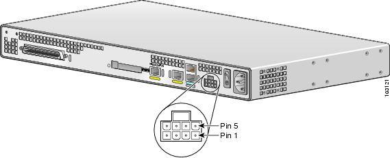
The +12V DC Input Power Supply
The +12V DC power connector to use with the Cisco VG224 voice gateway is the Molex Mini-Fit Jr. 5557 series, 8 circuit dual row (Molex P/N 39-01-2085). The VG224 +12V DC power input was designed to be used with an external UPS system, and it has status signals that are reported to the VG224.
Table 2-1 shows the connector pin assignment for the +12V DC power connector pin assignment.
Figure 2-1 shows the +12V DC power connector.
Figure 2-1 +12V DC Power Connector
Cable Types
The cable types that are used are dependent on the Cisco VG224 voice gateway that you are using. For more information, see the "Interfaces and Service Capabilities" section on page 1-4 and Appendix A, "Cable Specifications and Information."
•![]() Fast Ethernet cables (RJ-45-to-RJ-45 straight-through cables)
Fast Ethernet cables (RJ-45-to-RJ-45 straight-through cables)
•![]() Analog voice cables (RJ-21)
Analog voice cables (RJ-21)
Distance Limitations for Interface Cables
When planning your installation, consider distance limitations and potential electromagnetic interference (EMI) as defined by the Electronic Industries Association (EIA). Distance limitation information is included for the following VG ports:
•![]() Fast Ethernet Maximum Distance
Fast Ethernet Maximum Distance
•![]() FXS Analog Voice Port Maximum Distance
FXS Analog Voice Port Maximum Distance
Fast Ethernet Maximum Distance
The maximum segment distance for Fast Ethernet is 330 feet (100 meters) (specified in IEEE 802.3).
FXS Analog Voice Port Maximum Distance
The maximum distance is established by a total allowable loop resistance, including the phone or terminal equipment, of 600 ohms.
Interference Considerations
When you run cables for any significant distance in an electromagnetic field, interference can occur between the electromagnetic field and the signals on the cables. This has two implications for the installation of terminal plant cabling:
•![]() Unshielded plant cabling can emit radio interference.
Unshielded plant cabling can emit radio interference.
•![]() Strong electromagnetic interference (EMI), especially as caused by lightning or radio transmitters, can destroy the EIA/TIA-232 drivers and receivers in the Cisco VG224 voice gateway.
Strong electromagnetic interference (EMI), especially as caused by lightning or radio transmitters, can destroy the EIA/TIA-232 drivers and receivers in the Cisco VG224 voice gateway.
If you use twisted-pair cables with a good distribution of grounding conductors in your plant cabling, emitted radio interference is unlikely.
If you have cables exceeding recommended distances, or if you have cables that pass between buildings, give special consideration to the effect of lightning strikes or ground loops. If your site has these characteristics, consult experts in lightning suppression and shielding. The electromagnetic pulse caused by lightning or other high-energy phenomena can easily couple enough energy into unshielded conductors to destroy electronic devices.
Most data centers cannot resolve the infrequent, but potentially catastrophic problems just described without pulse meters and other special equipment. Take precautions to avoid these problems by providing a properly grounded and shielded environment and by installing electrical surge suppression.
If you remove any module, you must either install a module in its place or install a cover plate over the opening. All module openings must be either occupied or covered to prevent electromagnetic interference.
For advice on the prevention of electromagnetic interference, consult experts in radio-frequency interference (RFI).
 Feedback