Installing SODIMM Memory Modules in Cisco Network Modules for Caching and Content Delivery
Available Languages
Table Of Contents
Installing SODIMM Memory Modules in Cisco Network Modules for Caching and Content Delivery
Preventing Electrostatic Discharge Damage
Obtaining Technical Assistance
Installing SODIMM Memory Modules in Cisco Network Modules for Caching and Content Delivery
Product Number: MEM-CE-256D=
This document describes how to install small-outline, synchronous dynamic random-access memory, dual inline memory modules (SO DRAM DIMMs, or SODIMMs) in Cisco network modules that provide caching and content delivery. These include Cisco network module NM-CE-BP with any of the following expansion modules installed:
•
EM-CE-20G= or EM-CE-40G= with disk drive
•
Use this document with the Installing Expansion Modules on Cisco CE Network Modules for Caching and Content Delivery document, which you can access as follows:
•
•
http://www.cisco.com/univercd/cc/td/doc/product/access/acs_mod/cis2600/hw_inst/nm_inst/
nm_notes/mem_inst/index.htmIf you have questions or need help, see the "Obtaining Documentation" section.
This document contains the following sections:
•
•
Preventing Electrostatic Discharge Damage
Memory SODIMMs are sensitive to electrostatic discharge (ESD) damage. ESD damage, which can occur when electronic cards or components are handled improperly, results in complete or intermittent failures.
To prevent ESD damage, follow these guidelines:
•
•
•
•
•

Caution
Tools and Equipment Needed
You need the following tools and equipment to remove and install memory SODIMMs:
•
•
•
•
Installing a Memory SODIMM
To install a memory SODIMM, you need to remove the network module from the router chassis and then remove the expansion module from the network module.
To install a memory SODIMM, complete the following procedure.
Step 1
Step 2
Caution
Step 3
Caution
Step 4
Step 5
Figure 1 Screws to Remove if an Expansion Module with a SCSI Controller Is Installed
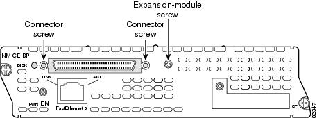
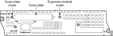
Figure 2 Screws to Remove if an Expansion Module with a Disk Drive Is Installed
Step 6

Note

Tip
Figure 3 Expansion Module with Disk Drive
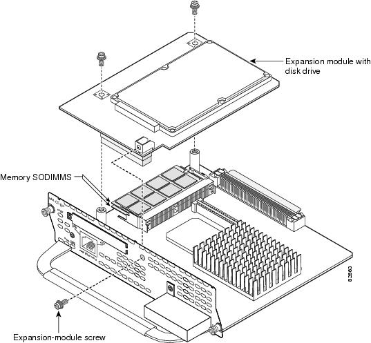
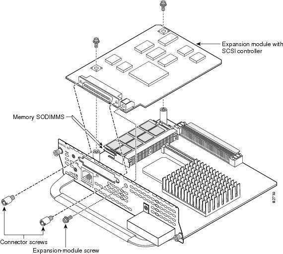
Figure 4 Expansion Module with SCSI Controller
Step 7
a.
b.
c.
d.
Step 8
a.
b.
Step 9
Caution
Note
Step 10
Step 11
Step 12
Obtaining Documentation
These sections explain how to obtain documentation from Cisco Systems.
World Wide Web
You can access the most current Cisco documentation on the World Wide Web at this URL:
Translated documentation is available at this URL:
http://www.cisco.com/public/countries_languages.shtml
Documentation CD-ROM
Cisco documentation and additional literature are available in a Cisco Documentation CD-ROM package, which is shipped with your product. The Documentation CD-ROM is updated monthly and may be more current than printed documentation. The CD-ROM package is available as a single unit or through an annual subscription.
Ordering Documentation
You can order Cisco documentation in these ways:
•
http://www.cisco.com/cgi-bin/order/order_root.pl
•
http://www.cisco.com/go/subscription
•
Documentation Feedback
You can submit comments electronically on Cisco.com. In the Cisco Documentation home page, click the Fax or Email option in the "Leave Feedback" section at the bottom of the page.
You can e-mail your comments to bug-doc@cisco.com.
You can submit your comments by mail by using the response card behind the front cover of your document or by writing to the following address:
Cisco Systems
Attn: Document Resource Connection
170 West Tasman Drive
San Jose, CA 95134-9883We appreciate your comments.
Obtaining Technical Assistance
Cisco provides Cisco.com as a starting point for all technical assistance. Customers and partners can obtain online documentation, troubleshooting tips, and sample configurations from online tools by using the Cisco Technical Assistance Center (TAC) Web Site. Cisco.com registered users have complete access to the technical support resources on the Cisco TAC Web Site.
Cisco.com
Cisco.com is the foundation of a suite of interactive, networked services that provides immediate, open access to Cisco information, networking solutions, services, programs, and resources at any time, from anywhere in the world.
Cisco.com is a highly integrated Internet application and a powerful, easy-to-use tool that provides a broad range of features and services to help you with these tasks:
•
•
•
•
•
If you want to obtain customized information and service, you can self-register on Cisco.com. To access Cisco.com, go to this URL:
Technical Assistance Center
The Cisco Technical Assistance Center (TAC) is available to all customers who need technical assistance with a Cisco product, technology, or solution. Two levels of support are available: the Cisco TAC Web Site and the Cisco TAC Escalation Center.
Cisco TAC inquiries are categorized according to the urgency of the issue:
•
•
•
•
The Cisco TAC resource that you choose is based on the priority of the problem and the conditions of service contracts, when applicable.
Cisco TAC Web Site
You can use the Cisco TAC Web Site to resolve P3 and P4 issues yourself, saving both cost and time. The site provides around-the-clock access to online tools, knowledge bases, and software. To access the Cisco TAC Web Site, go to this URL:
All customers, partners, and resellers who have a valid Cisco service contract have complete access to the technical support resources on the Cisco TAC Web Site. The Cisco TAC Web Site requires a Cisco.com login ID and password. If you have a valid service contract but do not have a login ID or password, go to this URL to register:
http://www.cisco.com/register/
If you are a Cisco.com registered user, and you cannot resolve your technical issues by using the Cisco TAC Web Site, you can open a case online by using the TAC Case Open tool at this URL:
http://www.cisco.com/tac/caseopen
If you have Internet access, we recommend that you open P3 and P4 cases through the Cisco TAC Web Site.
Cisco TAC Escalation Center
The Cisco TAC Escalation Center addresses priority level 1 or priority level 2 issues. These classifications are assigned when severe network degradation significantly impacts business operations. When you contact the TAC Escalation Center with a P1 or P2 problem, a Cisco TAC engineer automatically opens a case.
To obtain a directory of toll-free Cisco TAC telephone numbers for your country, go to this URL:
http://www.cisco.com/warp/public/687/Directory/DirTAC.shtml
Before calling, please check with your network operations center to determine the level of Cisco support services to which your company is entitled: for example, SMARTnet, SMARTnet Onsite, or Network Supported Accounts (NSA). When you call the center, please have available your service agreement number and your product serial number.
 Feedback
Contact Cisco
- Open a Support Case

- (Requires a Cisco Service Contract)