Network Analysis Module (NM-NAM)
Available Languages
Table Of Contents
Network Analysis Module (NM-NAM)
Prerequisites for the Network Analysis Module (NM-NAM)
Restrictions for the Network Analysis Module (NM-NAM)
Information About the Network Analysis Module (NM-NAM)
NM-NAM Operating Topologies and IP Address Assignments
Management Traffic—Choose One of the NM-NAM Interfaces
Monitored Traffic—Use One or Both of the NM-NAM Interfaces
NAM CLI Context-Sensitive Help
How to Configure and Manage the Network Analysis Module (NM-NAM)
Configuring the Analysis-Module Interface on the Router
Disabling AAA Login Authentication on the NAM Console Line
Opening and Closing a NAM Console Session from the Router
Configuring a Static Route to the NAM Through the Analysis-Module Interface
Enabling NAM Packet Monitoring
Enabling and Accessing the NAM Traffic Analyzer
Changing the NAM Root Password
Resetting the NAM Root Password to the Default Value
Opening and Closing a Telnet or SSH Session to the NAM
Types of NAM Software Upgrades
Upgrading the NAM Software—Patch
Upgrading the NAM Software—Full Image
Configuration Examples for the Network Analysis Module (NM-NAM)
NAM Management Interface Is Internal and Analysis-Module Interface Is IP Unnumbered: Example
NAM Management Interface Is External and Analysis-Module Interface Is IP Unnumbered: Example
Network Analysis Module (NM-NAM)
The Network Analysis Module (NM-NAM) feature is a network module that monitors and analyzes network traffic for a system using extended Remote Monitoring (RMON) standards, RMON2, and other Management Information Bases (MIBs).

Note
The Network Analysis Module (NAM) is available in multiple hardware forms for some Cisco routers and Catalyst switches. This document applies only to the NAM for branch routers, also known as modular access, multiservice, or integrated services routers.
NAM provides Layer 2 to Layer 7 visibility into network traffic for remote troubleshooting, real-time traffic analysis, application performance monitoring, capacity planning, and managing network-based services, including quality of service (QoS) and Voice over IP (VoIP). The NAM Traffic Analyzer is software that is embedded in the NM-NAM that gives you browser-based access to the RMON1, RMON2, DSMON, and voice monitoring features of the NAM.
Feature History for NM-NAM
Finding Support Information for Platforms and Cisco IOS Software Images
Use Cisco Feature Navigator to find information about platform support and Cisco IOS software image support. Access Cisco Feature Navigator at http://www.cisco.com/go/fn. You must have an account on Cisco.com. If you do not have an account or have forgotten your username or password, click Cancel at the login dialog box and follow the instructions that appear.
Contents
•
•
•
•
•
Prerequisites for the Network Analysis Module (NM-NAM)
•
•
•
Restrictions for the Network Analysis Module (NM-NAM)
General Restrictions
•
•
•
•
•
Traffic Monitoring Restrictions for the Internal NAM Interface
The following restrictions apply only to traffic that is monitored through the internal NAM interface:
•
•
•
•
–
–
•
–
–
–
Note
Information About the Network Analysis Module (NM-NAM)
To configure and manage the NM-NAM, you should understand the following concepts:
•
Note
NM-NAM Hardware
For information on hardware installation and cable connections, refer to the Cisco Network Modules Hardware Installation Guide.
Specifications
Faceplate and LEDs
Figure 1 NM-NAM Faceplate and LEDs
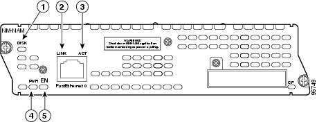
CalloutDISK
There is activity on the hard drive.
LINK
The Fast Ethernet connection is available to the network module.
ACT
There is activity on the Fast Ethernet connection.
PWR
Power is available to the network module.
EN
The module has passed self-test and is available to the router.
NAM User Interfaces
The NAM has three user interfaces:
•
•
•
NAM Network Interfaces
The NAM uses three interfaces for communication (see Figure 2):
Note
Figure 2 NAM Network Interfaces
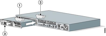
CalloutInternal NAM interface
NM-NAM internal
NAM CLI
Analysis-Module interface
Router internal
Cisco IOS CLI
External NAM interface
NM-NAM faceplate
NAM CLI
Analysis-Module Interface
The Analysis-Module interface is used to access the NAM console for the initial configuration. After configuring the NAM IP parameters, the Analysis-Module interface is typically used only during NAM software upgrades and while troubleshooting if the NAM Traffic Analyzer is inaccessible.
Visible only to the Cisco IOS software on the router, the Analysis-Module interface is an internal Fast Ethernet interface on the router that connects to the internal NAM interface. The Analysis-Module interface is connected to the router's Peripheral Component Interconnect (PCI) backplane, and all configuration and management of the Analysis-Module interface must be performed from the Cisco IOS CLI.
Internal NAM Interface
The internal NAM interface is used for monitoring traffic that passes through router interfaces. You can also select the internal NAM interface as the management interface for the NAM.
Visible only to the NAM software on the NM-NAM, the internal NAM interface is the Fast Ethernet interface on the NM-NAM that connects to the Analysis-Module interface on the router. The internal NAM interface is connected to the PCI bus on the NM-NAM, and all configuration and management of the internal NAM interface must be performed from the NAM software.
External NAM Interface
The external NAM interface can be used to monitor LAN traffic. You can also select the external NAM interface as the management interface for the NAM.
Visible only to the NAM software on the NM-NAM, the external NAM interface is the Fast Ethernet interface on the NM-NAM faceplate (see Figure 1). The external NAM interface supports data requests and data transfers from outside sources, and it provides direct connectivity to the LAN through an RJ-45 connector. All configuration and management of the external NAM interface must be performed from the NAM software.
NM-NAM Operating Topologies and IP Address Assignments
This section includes the following topics:
•
•
Management Traffic—Choose One of the NM-NAM Interfaces
Select either the internal or external NAM interface to handle management traffic such as IP, HTTP, SNMP, Telnet, and SSH. You cannot send management traffic through both NAM interfaces at the same time.
How you assign IP addresses on the NAM network interfaces depends on which NAM interface, internal or external, you use for management traffic. See the following sections:
•
•
Internal NAM Interface for Management Traffic—How to Assign IP Addresses
If you select the internal NAM interface to handle management traffic:
•
•
External NAM Interface for Management Traffic—How to Assign IP Addresses
If you select the external NAM interface to handle management traffic:
•
•
Monitored Traffic—Use One or Both of the NM-NAM Interfaces
You can use either or both the internal and external NAM interfaces for monitoring traffic:
•
•
The same interface can be used for both management traffic and monitored traffic simultaneously.
Internal NAM Interface—Monitor LAN and WAN Traffic
When you monitor traffic through the internal NAM interface, you must enable NAM packet monitoring on each router interface that you want to monitor. NAM packet monitoring uses Cisco Express Forwarding (CEF) to send a copy of each packet that is received or sent out of the router interface to the NAM.
Note
Monitoring traffic through the internal NAM interface enables the NAM to see any encrypted traffic after it has already been decrypted by the router.
Note
External NAM Interface—Monitor LAN Traffic
Monitoring traffic through the external NAM interface does not impact router resources. Therefore, we recommend that you use the external NAM interface to monitor LAN traffic.
To monitor ports on Ethernet switching cards or modules (NM-16ESW-x, NMD-36ESW-x, HWIC-4ESW, or HWIC-D-9ESW), configure a Switched Port Analyzer (SPAN) session whose destination is the Ethernet switch port that connects to the external NAM interface. For more information about configuring SPAN for these cards and modules, refer to the following documents:
•
•
Sample Operating Topologies
In each of the following topologies, the router's LAN interface is monitored through the external NAM interface, and the router's WAN interface is monitored through the internal NAM interface:
•
•
•
To see sample configurations for the following topologies, see the "Configuration Examples for the Network Analysis Module (NM-NAM)" section.
NAM Management Interface Is Internal and Analysis-Module Interface Is Assigned an IP Address
Figure 3 shows a sample topology, in which:
•
•
Figure 3 Sample Topology: NAM Management Interface Is Internal and Analysis-Module Interface Is Assigned an IP Address
CalloutAnalysis-Module interface
Router internal
Internal NAM interface (management)
NM-NAM internal
External NAM interface
NM-NAM faceplate
Serial interface
WAN interface card (WIC)
Fast Ethernet interface
Router rear panel
NAM Management Interface Is Internal and Analysis-Module Interface Is IP Unnumbered
Figure 4 shows a sample topology, in which:
•
•
•
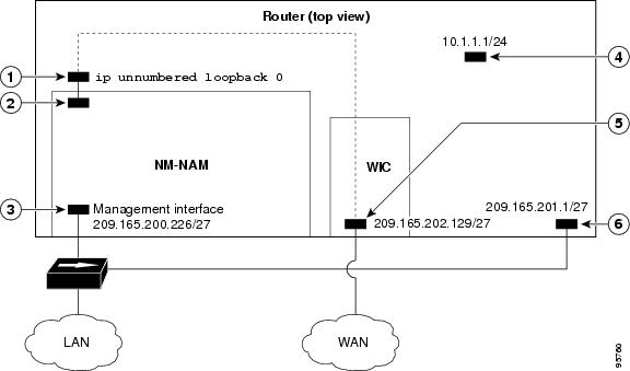
Figure 4 Sample Topology: NAM Management Interface Is Internal and Analysis-Module Interface Is IP Unnumbered
CalloutAnalysis-Module interface
Router internal
Internal NAM interface (management)
NM-NAM internal
External NAM interface
NM-NAM faceplate
Serial interface
WAN interface card (WIC)
Fast Ethernet interface
Router rear panel
NAM Management Interface Is External and Analysis-Module Interface Is IP Unnumbered
Figure 5 shows a sample topology where:
•
•
•
•
Figure 5 Sample Topology: NAM Management Interface Is External and Analysis-Module Interface Is IP Unnumbered
CalloutAnalysis-Module interface
Router internal
Internal NAM interface
NM-NAM internal
External NAM interface (management)
NM-NAM faceplate
Loopback interface
Router internal
Serial interface
WAN interface card (WIC)
Fast Ethernet interface
Router rear panel
NAM CLI
This section includes the following topics:
•
NAM CLI Access
There are three ways to access the NAM CLI:
•
•
•
Until you properly configure the NAM IP parameters, the only way to access the NAM CLI is by opening a NAM console session from the router.
NAM CLI Prompt
The NAM CLI prompt is
root@nam-system-hostname#. For example, if the NAM system hostname is configured as "nam1," then the NAM CLI prompt appears asroot@nam1#.If the NAM system hostname has not yet been configured, the NAM CLI prompt is
root@localhost#.Basic NAM CLI Commands
Table 2 briefly describes the basic NAM CLI commands that are used for initial configuration and maintenance of the NM-NAM. For a complete description of all NAM CLI commands, refer to the Network Analysis Module Command Reference for your NAM software release.
Note
NAM CLI Context-Sensitive Help
Table 3 shows how to use the NAM CLI context-sensitive help.
How to Configure and Manage the Network Analysis Module (NM-NAM)
This section contains the following procedures:
•
•
•
•
•
•
•
•
•
•
•
Configuring the Analysis-Module Interface on the Router
This section describes how to configure the Analysis-Module interface on the router. For general information on the Analysis-Module interface, see the "Analysis-Module Interface" section.
For information on assigning the IP address of the Analysis-Module interface, see the "NM-NAM Operating Topologies and IP Address Assignments" section.
SUMMARY STEPS
1.
2.
3.
4.
5.
6.
or
ip address ip-address mask7.
8.
9.
or
show running-configDETAILED STEPS
Step 1
enable
Example:Router> enable
Enables privileged EXEC mode.
•
Step 2
configure terminal
Example:Router# configure terminal
Enters global configuration mode.
Step 3
interface type number
Example:Router(config)# interface loopback 0
(Optional) Configures an interface, and enters interface configuration mode.
•
•
Step 4
ip address ip-address mask
Example:Router(config-if)# ip address 10.20.30.40 255.255.255.0
(Optional) Sets an IP address and mask for the interface.
•
•
Step 5
interface analysis-module slot/0
Example:Router(config)# interface analysis-module 1/0
Configures the Analysis-Module interface.
•
Step 6
ip unnumbered interface number
or
ip address ip-address mask
Example:Router(config-if)# ip unnumbered loopback 0
Example:Router(config-if)# ip address 10.20.30.40 255.255.255.0
Configures the Analysis-Module interface as IP unnumbered and specifies the interface whose IP address is borrowed by the Analysis-Module interface.
or
Sets an IP address and mask on the Analysis-Module interface.
•
Step 7
no shutdown
Example:Router(config-if)# no shutdown
Activates the Analysis-Module interface.
Step 8
end
Example:Router(config-if)# end
Router#
Returns to privileged EXEC mode.
Step 9
show ip interface brief
or
show running-config
Example:Router# show ip interface brief
Example:Router# show running-config
Displays the IP addresses and summary status of the interfaces.
or
Displays the contents of the currently running configuration file.
•
•

Tip
Examples
This section provides the following examples:
•
•
•
•
Configuring the Analysis-Module Interface—Routable Subnet: Example
In the following example, the Analysis-Module interface is configured with a routable IP address. The NM-NAM is installed in router slot 2.
!interface Analysis-Module 2/0ip address 209.165.200.230 255.255.255.224no shutdownConfiguring the Analysis-Module Interface—IP Unnumbered with Routable Subnet: Example
In the following example, the Analysis-Module interface is IP unnumbered and borrows the IP address of the Fast Ethernet interface. The IP address is from a routable subnet, and the NM-NAM is installed in router slot 1.
!interface FastEthernet 0/0ip address 209.165.202.129 255.255.255.224no shutdown!interface Analysis-Module 1/0ip unnumbered FastEthernet 0/0no shutdown!Configuring the Analysis-Module Interface—IP Unnumbered with Subnet That Is Not Routable: Example
In the following example, the Analysis-Module interface is IP unnumbered and borrows a loopback interface IP address that is not routable. The NM-NAM is installed in router slot 3.
!interface loopback 0ip address 10.20.30.40 255.255.255.0!interface Analysis-Module 3/0ip unnumbered loopback 0no shutdown!Sample Output for the show ip interface brief Command
Router# show ip interface briefInterface IP-Address OK? Method Status ProtocolFastEthernet0/0 172.20.105.213 YES NVRAM up upFastEthernet0/1 172.20.105.53 YES NVRAM up upAnalysis-Module2/0 10.1.1.1 YES manual up upRouter#What to Do Next
If you configured authentication, authorization, and accounting (AAA) on your router, then proceed to the "Disabling AAA Login Authentication on the NAM Console Line" section.
Otherwise, proceed to the "Opening and Closing a NAM Console Session from the Router" section.
Disabling AAA Login Authentication on the NAM Console Line
If you configured authentication, authorization, and accounting (AAA) on your router, then you may have to log in twice to open a NAM console session from the router: first with your AAA username and password, and second with the NAM login and password.
If you do not want to log in twice to open a NAM console session from the router, then disable AAA login authentication on the router's NAM console line by performing the steps in this section.
Note, however, that if your router contains both the NM-NAM and the NM-CIDS, the Cisco intrusion detection system network module, then AAA can be a useful tool for centrally controlling access to both network modules. For information about AAA, refer to the Cisco IOS Security Configuration Guide.
SUMMARY STEPS
1.
2.
3.
4.
5.
6.
7.
DETAILED STEPS
Step 1
enable
Example:Router> enable
Enables privileged EXEC mode.
•
Step 2
configure terminal
Example:Router# configure terminal
Enters global configuration mode.
Step 3
aaa authentication login list-name none
Example:Router(config)# aaa authentication login nam none
Creates a local authentication list.
•
Step 4
line number
Example:Router(config)# line 33
Enters line configuration mode for the line to which you want to apply the authentication list.
•
number = (32 x slot) + 1
Step 5
login authentication list-name
Example:Router(config-line)# login authentication nam
Applies the authentication list to the line.
•
Step 6
end
Example:Router(config-line)# end
Router#
Returns to privileged EXEC mode.
Step 7
show running-config
Example:Router# show running-config
Displays the contents of the currently running configuration file.
•
What to Do Next
Proceed to the "Opening and Closing a NAM Console Session from the Router" section.
Opening and Closing a NAM Console Session from the Router
This section describes how to open and close a NAM console session from the router.
SUMMARY STEPS
1.
2.
3.
or
If a username prompt appears, then log in with your AAA username and password.4.
5.
or
If you have not changed the password from the factory-set default, enter root as the root password.6.
7.
8.
9.
10.
DETAILED STEPS
Step 1
enable
Example:Router> enable
Enables privileged EXEC mode.
•
Step 2
service-module analysis-module slot/0 session
Example:Router# service-module analysis-module 1/0 session
Example:Router# service-module analysis-module 1/0 session clear[confirm][OK]Router# service-module analysis-module 1/0 session
Establishes a console session with the NAM.
•
Step 3
Press Return.
or
If a username prompt appears, then log in with your AAA username and password.
Example:Trying 10.1.1.1, 2065 ... Open
<Press Return>
Cisco Network Analysis Module (NM-NAM)
nam1.cisco.com login:
Example:Trying 10.1.1.1, 2065... Open
User Access Verification
Username: myaaausername
Password: <myaaapassword>
Cisco Network Analysis Module (NM-NAM)
nam1.cisco.com login:
Activates the NAM console line.
or
Completes AAA login authentication and activates the NAM console line.
•
Step 4
At the login prompt, enter root.
Example:login: root
Accesses the root (read/write) level of NAM.
Step 5
At the password prompt, enter your password.
or
If you have not changed the password from the factory-set default, enter root as the root password.
Example:Password: <root>
—
Step 6
Perform the tasks that you need to perform in the NAM CLI. When you want to end the NAM console session and return to the Cisco IOS CLI, complete Step 7 through Step 10.
For initial configuration tasks, see the "Configuring the NM-NAM" section.
For help using NAM CLI commands, see the "NAM CLI Context-Sensitive Help" section.
Step 7
exit
Example:root@localhost(sub-custom-filter-capture)# exit
root@localhost# exit
login:
Logs out of the NAM system or leaves a subcommand mode.
•
Step 8
Hold Ctrl-Shift and press 6. Release all keys, and then press x.
Example:login: <suspend keystroke>
Router#
Suspends and closes the Telnet session.
Step 9
disconnect
Example:Router# disconnect
Disconnects a line.
Step 10
Press Enter.
Example:Closing connection to 10.20.30.40 [confirm] <Enter>
Confirms that you want to disconnect the line.
Examples
This section provides the following examples:
Opening and Closing a NAM Console Session When AAA Authentication Is Not Configured or Is Disabled on the NAM Console Line: Example
In the following example, a NAM console session is opened and closed from the router. The NM-NAM is installed in router slot 2.
Router# service-module analysis-module 2/0 sessionTrying 10.1.1.1, 2065 ... OpenCisco Network Analysis Module (NM-NAM)nam1.cisco.com login: rootPassword: <password>Terminal type: vt100Cisco Network Analysis Module (NM-NAM) Console, 3.2Copyright (c) 1999-2003 by cisco Systems, Inc.WARNING! Default password has not been changed!root@nam1.cisco.com#root@nam1.cisco.com# exitCisco Network Analysis Module (NM-NAM)nam1.cisco.com login: <suspend keystroke>Router# disconnectClosing connection to 10.1.1.1 [confirm] <Enter>Deleting login sessionOpening and Closing a NAM Console Session When AAA Authentication Is Configured and Enabled on the NAM Console Line: Example
In the following example, a NAM console session is opened and closed from the router. The NM-NAM is installed in router slot 2.
Router# service-module analysis-module 2/0 sessionTrying 10.1.1.1, 2065 ... OpenUser Access VerificationUsername: myaaausernamePassword: <myaaapassword>Cisco Network Analysis Module (NM-NAM)nam1.cisco.com login: rootPassword: <nampassword>Terminal type: vt100Cisco Network Analysis Module (NM-NAM) Console, 3.2Copyright (c) 1999-2003 by cisco Systems, Inc.WARNING! Default password has not been changed!root@nam1.cisco.com#root@nam1.cisco.com# exitCisco Network Analysis Module (NM-NAM)nam1.cisco.com login: <suspend keystroke>Router# disconnectClosing connection to 10.1.1.1 [confirm] <Enter>Deleting login sessionTroubleshooting Tips
Make sure that the NAM console line is clear by entering the service-module analysis-module slot/0 session clear command in privileged EXEC mode.
What to Do Next
Proceed to the "Configuring the NM-NAM" section.
Configuring the NM-NAM
This section describes how to configure the NM-NAM to establish network connectivity and configure IP parameters. This task must be performed from the NAM CLI. For more advanced NAM configuration, use the NAM Traffic Analyzer (web GUI) or refer to the Network Analysis Module Command Reference for your NAM software release.
For information on assigning IP addresses, see the "NM-NAM Operating Topologies and IP Address Assignments" section.
Prerequisites
Before performing this task, access the NAM console by performing Step 1 through Step 5 in the "Opening and Closing a NAM Console Session from the Router" section.
SUMMARY STEPS
1.
2.
3.
4.
5.
or
exsession on ssh6.
7.
8.
9.
10.
DETAILED STEPS
Step 1
ip interface {internal | external}
Example:root@localhost# ip interface internal
Example:root@localhost# ip interface external
Specifies which NAM interface will handle management traffic.
Step 2
ip address ip-address subnet-mask
Example:root@localhost# ip address 172.20.104.126 255.255.255.248
Configures the NAM system IP address.
•
Step 3
ip broadcast broadcast-address
Example:root@localhost# ip broadcast 10.255.255.255
(Optional) Configures the NAM system broadcast address.
Step 4
ip gateway ip-address
Example:root@localhost# ip gateway 172.20.104.125
Configures the NAM system default gateway address.
Step 5
exsession on
or
exsession on ssh
Example:root@localhost# exsession on
Example:root@localhost# exsession on ssh
(Optional) Enables outside logins.
•
•
Note
Step 6
ip domain name
Example:root@localhost# ip domain cisco.com
(Optional) Sets the NAM system domain name.
Step 7
ip host name
Example:root@localhost# ip host nam1
(Optional) Sets the NAM system hostname.
Step 8
ip nameserver ip-address [ip-address][ip-address]
Example:root@nam1# ip nameserver 209.165.201.1
(Optional) Sets one or more NAM system name servers.
•
Step 9
ping {host | ip-address}
Example:root@nam1# ping 10.20.30.40
Checks connectivity to a network device.
•
Step 10
show ip
Example:root@nam1# show ip
Displays the NAM IP parameters.
•
Examples
This section provides the following examples:
•
•
•
Configuring the NM-NAM: Example
In the following example, the external NAM interface is used for management traffic. The HTTP server and Telnet access are enabled. The resulting NAM CLI prompt is
root@nam1.cisco.com#.!ip address 172.20.105.215 255.255.255.192!ip host "nam1"!ip domain "cisco.com"!ip gateway 172.20.105.210!ip broadcast 10.255.255.255!ip nameserver 209.165.201.29!ip interface external!ip http server enable!exsession on!Checking Network Connectivity with Ping: Example
root@nam1.cisco.com# ping 172.20.105.213PING 172.20.105.213 (172.20.105.213) from 172.20.105.215 : 56(84) bytes of data.64 bytes from 172.20.105.213: icmp_seq=0 ttl=255 time=353 usec64 bytes from 172.20.105.213: icmp_seq=1 ttl=255 time=289 usec64 bytes from 172.20.105.213: icmp_seq=2 ttl=255 time=284 usec64 bytes from 172.20.105.213: icmp_seq=3 ttl=255 time=283 usec64 bytes from 172.20.105.213: icmp_seq=4 ttl=255 time=297 usec--- 172.20.105.213 ping statistics ---5 packets transmitted, 5 packets received, 0% packet lossround-trip min/avg/max/mdev = 0.283/0.301/0.353/0.028 msroot@nam1.cisco.com#Sample Output for the show ip NAM CLI Command
root@nam1.cisco.com# show ipIP address: 172.20.105.215Subnet mask: 255.255.255.192IP Broadcast: 10.255.255.255IP Interface: ExternalDNS Name: nam1.cisco.comDefault Gateway: 172.20.105.210Nameserver(s): 209.165.201.29HTTP server: EnabledHTTP secure server: DisabledHTTP port: 80HTTP secure port: 443TACACS+ configured: NoTelnet: EnabledSSH: Disabledroot@nam1.cisco.com#What to Do Next
If you selected the internal NAM interface to handle management traffic in Step 1, then proceed to the "Configuring a Static Route to the NAM Through the Analysis-Module Interface" section.
If you plan to monitor traffic through the internal NAM interface, then proceed to the "Enabling NAM Packet Monitoring" section.
If you do not plan to monitor traffic through the internal NAM interface, then proceed to the "Enabling and Accessing the NAM Traffic Analyzer" section.
Configuring a Static Route to the NAM Through the Analysis-Module Interface
This section describes how to ensure that the router can route packets to the NAM by configuring a static route through the Analysis-Module interface.
If you select the internal NAM interface to handle management traffic, then configuring a static route to the NAM through the Analysis-Module interface is:
•
•
If you select the external NAM interface to handle management traffic, then you do not need to perform this task. Proceed to the "What to Do Next" section.
SUMMARY STEPS
1.
2.
3.
4.
5.
DETAILED STEPS
Examples
This section provides the following examples:
•
•
Configuring a Static Route to the NAM Through the Analysis-Module Interface: Example
In the following example, a static route is configured to the NAM whose system IP address is 172.20.105.215. The NM-NAM is installed in router slot 1.
!ip route 172.20.105.215 255.255.255.192 analysis-module 1/0!interface FastEthernet 0/0ip address 209.165.202.129 255.255.255.224no shutdown!interface Analysis-Module 1/0ip unnumbered FastEthernet 0/0no shutdown!Verifying Network Connectivity with Ping: Example
In the following example, entering the ping command verifies network connectivity to the NAM with IP address 172.20.105.215.
Router# ping 172.20.105.215Type escape sequence to abort.Sending 5, 100-byte ICMP Echos to 172.20.105.215, timeout is 2 seconds:!!!!!Success rate is 100 percent (5/5), round-trip min/avg/max = 1/1/1 msRouter#What to Do Next
If you plan to monitor traffic through the internal NAM interface, then proceed to the "Enabling NAM Packet Monitoring" section.
If you do not plan to monitor traffic through the internal NAM interface, then proceed to the "Enabling and Accessing the NAM Traffic Analyzer" section.
Enabling NAM Packet Monitoring
This section describes how to enable NAM packet monitoring on router interfaces that you want to monitor through the internal NAM interface.
When you enable NAM packet monitoring on an interface, CEF sends an extra copy of each IP packet that is received or sent out on that interface to the NAM through the Analysis-Module interface on the router and the internal NAM interface.
SUMMARY STEPS
1.
2.
3.
4.
or
interface type slot/wic-slot/port5.
6.
7.
8.
DETAILED STEPS
Step 1
enable
Example:Router> enable
Enables privileged EXEC mode.
•
Step 2
configure terminal
Example:Router# configure terminal
Enters global configuration mode.
Step 3
ip cef
Example:Router(config)# ip cef
Enables the CEF switching path.
Step 4
interface type slot/port
or
interface type slot/wic-slot/port
Example:Router(config)# interface serial 0/0
Selects an interface for configuration.
Step 5
analysis-module monitoring
Example:Router(config-if)# analysis-module monitoring
Enables NAM packet monitoring on the interface.
Step 6
Repeat Step 4 and Step 5 for each interface that you want the NAM to monitor through the internal NAM interface.
—
Step 7
end
Example:Router(config-if)# end
Router#
Returns to privileged EXEC mode.
Step 8
show running-config
Example:Router# show running-config
Displays the contents of the currently running configuration file.
•
Example
This section provides the following example:
•
Enabling NAM Packet Monitoring: Example
In the following example, NAM packet monitoring is enabled on the serial interfaces:
interface Serial 0/0ip address 172.20.105.213 255.255.255.240ip route-cache flowspeed autofull-duplexanalysis-module monitoringno mop enabled!interface Serial 0/1ip address 172.20.105.53 255.255.255.252ip route-cache flowduplex autospeed autoanalysis-module monitoring!interface Analysis-Module 2/0ip address 10.1.1.1 255.255.255.0hold-queue 60 out!What to Do Next
Proceed to the "Enabling and Accessing the NAM Traffic Analyzer" section.
Enabling and Accessing the NAM Traffic Analyzer
This section describes how to enable and access the NAM Traffic Analyzer (web GUI).
Prerequisites
•
•
Restrictions
You can use the HTTP server or the HTTP secure server, but you cannot use both simultaneously.
SUMMARY STEPS
1.
or
Open a Telnet or SSH session to the NAM. See the "Opening and Closing a Telnet or SSH Session to the NAM" section.2.
or
ip http secure server enable3.
or
Press Return to enter the default web username "admin".4.
5.
6.
7.
DETAILED STEPS
Step 1
Open a NAM console session from the router. See the "Opening and Closing a NAM Console Session from the Router" section.
or
Open a Telnet or SSH session to the NAM. See the "Opening and Closing a Telnet or SSH Session to the NAM" section.
Accesses the NAM CLI.
Step 2
ip http server enable
or
ip http secure server enable
Example:root@localhost# ip http server enable
Example:root@localhost# ip http secure server enable
Enables the HTTP server.
or
Enables the HTTP secure server (HTTPs).
Step 3
Enter a web username.
or
Press Return to enter the default web username "admin".
Example:Please enter a web administrator user name [admin]: joeadmin
Example:Please enter a web administrator user name [admin]: <cr>
Configures a web username.
•
•
Step 4
Enter a password.
Example:New password: <adminpswd>Configures a password for the web username.
Step 5
Enter the password again.
Example:Confirm password: <adminpswd>Confirms the password for the web username.
Step 6
On your PC, open a web browser.
—
Step 7
In the web browser, enter the NAM system IP address or hostname as the URL.
Example:http://172.20.105.215/
Example:https://172.20.105.215/
Example:http://nam1/
Opens the NAM Traffic Analyzer in your web browser.
•
Examples
This section provides the following examples:
•
•
Enabling the NAM Traffic Analyzer: Example
root@nam1# ip http server enableEnabling HTTP server...No web users are configured.Please enter a web administrator user name [admin]: <cr>New password: <pswd>Confirm password: <pswd>User admin added.Successfully enabled HTTP server.root@nam1#Accessing the NAM Traffic Analyzer: Example
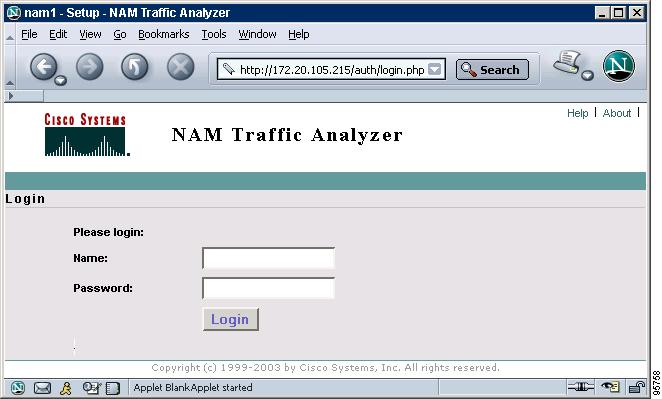
Figure 6 shows the NAM Traffic Analyzer login page that appears when you enter the NAM system IP address or hostname as the URL in a web browser.
Figure 6 Sample NAM Traffic Analyzer Login Page
What to Do Next
For information on the NAM Traffic Analyzer, refer to the User Guide for the Network Analysis Module Traffic Analyzer for your NAM software release. This document is available on Cisco.com and as online help within the NAM Traffic Analyzer application.
Changing the NAM Root Password
This section describes how to set a new password to access the root (read/write) level of NAM, where you can enter NAM CLI commands. The factory-set default root password is "root".
Prerequisites
Before performing this task, access the NAM console by performing Step 1 through Step 5 in the "Opening and Closing a NAM Console Session from the Router" section.
SUMMARY STEPS
1.
2.
3.
4.
5.
6.
DETAILED STEPS
Examples
This section provides the following examples:
•
•
Changing the NAM Root Password: Example
root@nam1.cisco.com# password rootChanging password for user rootNew UNIX password: <rtpswd>Retype new UNIX password: <rtpswd>passwd:all authentication tokens updated successfullyroot@nam1.cisco.com#root@nam1.cisco.com# exitVerifying the NAM Root Password: Example
nam1.cisco.com login: rootPassword: <rtpswd>Terminal type: vt100Cisco Network Analysis Module (NM-NAM) Console, 3.2Copyright (c) 1999-2003 by cisco Systems, Inc.root@nam1.cisco.com#root@nam1.cisco.com# exitTroubleshooting Tips
If you forget the NAM root password, see the "Resetting the NAM Root Password to the Default Value" section.
Resetting the NAM Root Password to the Default Value
This section describes how to reset the NAM root password to the default value of "root". Use this procedure when you cannot remember the NAM root password but need to access the NAM CLI.
Note
SUMMARY STEPS
1.
2.
3.
4.
5.
6.
7.
8.
9.
10.
11.
12.
DETAILED STEPS
Step 1
enable
Example:Router> enable
Enables privileged EXEC mode.
•
Step 2
service-module analysis-module slot/0 reload
Example:Router# service-module analysis-module 1/0 reload
Reloads the software on the NM-NAM.
Step 3
y
Example:Do you want to proceed with reload?[confirm] y
Confirms that you want to proceed with the NAM software reload.
Step 4
service-module analysis-module slot/0 session
Example:Router# service-module analysis-module 1/0 session
Example:Router# service-module analysis-module 1/0 session clear[confirm][OK]Router# service-module analysis-module 1/0 session
Establishes a console session with the NAM.
•
•
Step 5
When prompted, enter *** to change the boot configuration.
Example:Please enter '***' to change boot configuration: ***
Interrupts the boot loader.
•
•
Step 6
boot flash
Example:ServicesEngine boot-loader> boot flash
Loads the NAM helper image.
•
Step 7
When prompted to select from the helper menu, enter 6.
Example:Selection [12345678rh]: 6
Selects the menu option to reset the root password to the default value of "root".
Step 8
When prompted to select from the helper menu, enter r.
Example:Selection [12345678rh]:r
Selects the menu option to exit the helper and reset the NAM.
Step 9
y
Example:About to exit and reset Services Engine.
Are you sure? [y/N] y
Confirms that you want to exit the helper and reset the NAM.
•
Step 10
Hold Ctrl-Shift and press 6. Release all keys, and then press x.
Example:login: <suspend keystroke>
Router#
Suspends and closes the Telnet session.
Step 11
disconnect
Example:Router# disconnect
Disconnects a line.
Step 12
Press Enter.
Example:Closing connection to 10.20.30.40 [confirm] <Enter>
Confirms that you want to disconnect the line.
Example
This section provides the following example:
•
Resetting the NAM Root Password to the Default Value: Example
Router# service-module analysis-module 1/0 reloadDo you want to proceed with reload?[confirm] yTrying to reload Service Module Analysis-Module1/0.Router# service-module analysis-module 1/0 sessionTrying 172.20.104.87, 2033 ... Open.<debug output omitted>.Booting from flash..., please wait.[BOOT-ASM]7Please enter '***' to change boot configuration: ***ServicesEngine Bootloader Version :1.0.6aNServicesEngine boot-loader> boot flash.<debug output omitted>.==============================================================================Cisco Systems, Inc.Services engine helper utility for NM-NAMVersion 1.1(1) [200311111641]-----Main menu1 - Download application image and write to HDD2 - Download application image and reformat HDD3 - Download bootloader and write to flash4 - Download helper and write to flash5 - Display software versions6 - Reset application image CLI passwords to default7 - Change file transfer method (currently ftp/http)8 - Show upgrade log9 - Send Pingr - Exit and reset Services Engineh - Exit and shutdown Services EngineSelection [123456789rh]: 6Restored default CLI passwords of application image.==============================================================================Cisco Systems, Inc.Services engine helper utility for NM-NAMVersion 1.1(1) [200311111641]-----Main menu1 - Download application image and write to HDD2 - Download application image and reformat HDD3 - Download bootloader and write to flash4 - Download helper and write to flash5 - Display software versions6 - Reset application image CLI passwords to default7 - Change file transfer method (currently ftp/http)8 - Show upgrade log9 - Send Pingr - Exit and reset Services Engineh - Exit and shutdown Services EngineSelection [123456789rh]: rAbout to exit and reset Services Engine.Are you sure? [y/N] yINITSending all processes the TERM signal...Sending all processes the KILL signal...Unmounting file systems:Please stand by while rebooting the system...Restarting system..<debug output omitted>.Cisco Network Analysis Module (NM-NAM)nam1.cisco.com login: <suspend keystroke>Router#Router# disconnectClosing connection to 10.1.1.1 [confirm] <Enter>Deleting login sessionTroubleshooting Tips
If you have trouble opening a NAM console session from the router, make sure that the NAM console line is clear by entering the service-module analysis-module slot/0 session clear command in privileged EXEC mode.
What to Do Next
Verify that the default root password of "root" is accepted by performing Step 1 through Step 5 in the "Opening and Closing a NAM Console Session from the Router" section.
To change the NAM root password, see the "Changing the NAM Root Password" section.
Opening and Closing a Telnet or SSH Session to the NAM
This section describes how to open and close a Telnet or SSH session to the NAM. This task is not commonly performed, because you would typically use the NAM Traffic Analyzer (web GUI) to monitor and maintain the NAM. If, however, you cannot access the NAM Traffic Analyzer, then you might want to use Telnet or SSH to troubleshoot from the NAM CLI.
If your NM-NAM is not properly configured for Telnet or SSH access (see the following Prerequisites section), then you can open a Telnet session to the router in which the NM-NAM is installed, and then open a NAM console session from the router. See the "Opening and Closing a NAM Console Session from the Router" section.
Prerequisites
•
•
–
–
Telnet Prerequisites
•
SSH Prerequisites
•
•
SUMMARY STEPS
1.
or
ssh {ip-address | hostname}2.
3.
or
If you have not changed the password from the factory-set default, enter root as the root password.4.
5.
6.
DETAILED STEPS
Step 1
telnet {ip-address | hostname}
or
ssh {ip-address | hostname}
Example:Router# telnet 10.20.30.40
Example:Router# ssh 10.20.30.40
Logs in to a host that supports Telnet.
or
Starts an encrypted session with a remote networking device.
•
Step 2
At the login prompt, enter root.
Example:login: root
Accesses the root (read/write) level of NAM.
Step 3
At the password prompt, enter your password.
or
If you have not changed the password from the factory-set default, enter root as the root password.
Example:Password: root
—
Step 4
Perform the tasks that you need to perform in the NAM CLI. When you want to end the Telnet or SSH session to the NAM and return to the Cisco IOS CLI, complete Step 5 and Step 6.
For help using NAM CLI commands, see the "NAM CLI Context-Sensitive Help" section.
Step 5
exit
Example:root@localhost(sub-custom-filter-capture)# exit
root@localhost#
Leaves a subcommand mode.
•
Step 6
logout
Example:root@localhost# logout
Connection closed by foreign host.
Logs out of the NAM system.
Examples
This section provides the following examples:
•
•
Opening and Closing a Telnet Session to the NAM Using the NAM System IP Address: Example
Router> telnet 172.20.105.215Trying 172.20.105.215 ... OpenCisco Network Analysis Module (NM-NAM)login: rootPassword: <password>Terminal type: vt100Cisco Network Analysis Module (NM-NAM) Console, 3.2Copyright (c) 1999-2003 by cisco Systems, Inc.WARNING! Default password has not been changed!root@nam.cisco.com#root@nam.cisco.com# logout[Connection to 172.20.105.215 closed by foreign host]Router>Opening and Closing an SSH Session to the NAM Using the NAM System Hostname: Example
host [/home/user] ssh -l root nmnam2root@nmnam2's password: <password>Terminal type: vt100Cisco Network Analysis Module (NM-NAM) Console, 3.2Copyright (c) 1999-2003 by cisco Systems, Inc.WARNING! Default password has not been changed!root@nmnam2.cisco.com#root@nmnam2.cisco.com# logoutConnection to nmnam2 closed.host [/home/user]Upgrading the NAM Software
This section describes how to upgrade the NAM software. This task is performed from the NAM CLI.
NAM Software Images
The NM-NAM contains three NAM software images:
•
•
•
Types of NAM Software Upgrades
NAM software upgrades are available in two forms:
•
•
Prerequisites
•
•
Perform one of the following tasks in this section, depending on whether you are adding a patch to your NAM application or are performing a full software image upgrade:
•
•
Upgrading the NAM Software—Patch
Perform this task to add a patch to your NAM application image. This task is performed from the NAM CLI.
SUMMARY STEPS
1.
or
patch ftp://user@host/full-path/filename2.
DETAILED STEPS
Upgrading the NAM Software—Full Image
Perform this task to upgrade one of your NAM software images to a new release. This task is performed from the NAM CLI.
SUMMARY STEPS
1.
2.
3.
4.
5.
6.
7.
8.
9.
DETAILED STEPS
Step 1
reboot
Example:root@nam1.cisco.com# reboot
Shuts down and restarts the NAM.
•
Step 2
y
Example:Reboot the NAM? (Y/N) [N]: y
Confirms that you want to reboot the NAM.
•
Step 3
When prompted, enter *** to change the boot configuration.
Example:Please enter '***' to change boot configuration: ***
Interrupts the boot loader.
•
•
Step 4
boot flash
Example:ServicesEngine boot-loader> boot flash
Loads the NAM helper image.
•
Step 5
When prompted to select from the helper menu, enter 1 or 2.
Example:Selection [12345678rh]: 1
Example:Selection [12345678rh]: 2
Selects the menu option to download the NAM software image onto the NM-NAM internal memory.
•
•
•
Step 6
ftp://ip-address/path/nam-image-file
Example:Download NAM application image via ftp and write to HDD
URL of application image []: ftp://172.20.98.136/dir1/dir2/nam-image.bin.gz
Specifies the FTP location and filename of the NAM software image.
Step 7
y
Example:Do you want to proceed installing it? [y/N] y
Confirms that you want to install the specified NAM software image.
Step 8
r
Example:Selection [12345678rh]:r
Selects the menu option to exit the helper and reset the NAM.
Step 9
y
Example:About to exit and reset Services Engine.
Are you sure? [y/N] y
Confirms that you want to exit the helper and reset the NAM.
•
Examples
This section provides the following examples:
•
•
Upgrading the NAM Software—Patch: Example
Router> enablePassword: <password>Router#Router# service-module analysis-Module 1/0 sessionTrying 172.20.104.86, 2033 ... OpenCisco Network Analysis Module (NM-NAM)nam1.cisco.com login: rootPassword: <password>Terminal type:vt100Cisco Network Analysis Module (NM-NAM) Console, 3.2(0.10)Copyright (c) 1999-2003 by cisco Systems, Inc.WARNING! Default password has not been changed!root@nam1.cisco.com# patch ftp://person@examplehost/dir/subdir/nam-app.3-2.cryptoK9.patch.1-0.binProceeding with installation. Please do not interrupt.If installation is interrupted, please try again.Downloading nam-app.3-2.cryptoK9.patch.1-0.bin. Please wait...Password for person@examplehost: <mypwd>ftp://person@examplehost/dir/subdir/nam-app.3-2.cryptoK9.patch.1-0.bin(1K)/usr/local/nam/patch/wor [########################] 1K | 104.43K/s1894 bytes transferred in 0.02 sec (102.35k/sec)Verifying nam-app.3-2.cryptoK9.patch.1-0.bin. Please wait...Patch nam-app.3-2.cryptoK9.patch.1-0.bin verified.Applying /usr/local/nam/patch/workdir/nam-app.3-2.cryptoK9.patch.1-0.bin.Please wait...########################################### [100%]########################################### [100%]Patch applied successfully.root@nam1.cisco.com# show patchesTue Aug 31 21:04:28 2004 Patch:nam-app.3-2.strong-crypto-patchK9-1-0Description:Strong Crypto Patch for NAM.root@nam1.cisco.com#Upgrading the NAM Software—Full Image: Example
Router> enablePassword: <password>Router#Router# service-module analysis-Module 1/0 sessionTrying 172.20.104.86, 2033 ... OpenCisco Network Analysis Module (NM-NAM)nam1.cisco.com login: rootPassword: <password>Terminal type:vt100Cisco Network Analysis Module (NM-NAM) Console, 3.2(0.10)Copyright (c) 1999-2003 by cisco Systems, Inc.WARNING! Default password has not been changed!root@nam1.cisco.com#root@nam1.cisco.com# rebootReboot the NAM? (Y/N) [N]: ySystem reboot in process....<debug output omitted>.Booting from flash..., please wait.[BOOT-ASM]7Please enter '***' to change boot configuration: ***ServicesEngine Bootloader Version :1.0.6-NAMServicesEngine boot-loader>ServicesEngine boot-loader> boot flash.<debug output omitted>.==============================================================================Cisco Systems, Inc.Services engine helper utility for NM-NAMVersion 1.1(1) [200311111641]-----Main menu1 - Download application image and write to HDD2 - Download application image and reformat HDD3 - Download bootloader and write to flash4 - Download helper and write to flash5 - Display software versions6 - Reset application image CLI passwords to default7 - Change file transfer method (currently ftp/http)8 - Show upgrade log9 - Send Pingr - Exit and reset Services Engineh - Exit and shutdown Services EngineSelection [123456789rh]: 1-----Download NAM application image via ftp and write to HDDURL of application image []: ftp://172.20.98.136/dir1/dir2/nam-image.bin.gzGetting c6svc-nam.mainline-DAILY_20030825.bin.gz from 171.69.17.19 via ftp.ftp://172.20.98.136/dir1/dir2/nam-image.bin.gz(46389K)- [########################] 46389K | 7421.38K/s47502347 bytes transferred in 6.25 sec (7421.14k/sec)upgrade.bin size:48241545File transfer successful.Checking upgrade.binDo you want to proceed installing it? [y/N] y.<debug output omitted>.Application image upgrade complete. You can boot the image now.==============================================================================Cisco Systems, Inc.Services engine helper utility for NM-NAMVersion 1.1(1) [200311111641]-----Main menu1 - Download application image and write to HDD2 - Download application image and reformat HDD3 - Download bootloader and write to flash4 - Download helper and write to flash5 - Display software versions6 - Reset application image CLI passwords to default7 - Change file transfer method (currently ftp/http)8 - Show upgrade log9 - Send Pingr - Exit and reset Services Engineh - Exit and shutdown Services EngineSelection [123456789rh]: rAbout to exit and reset Services Engine.Are you sure? [y/N] yTroubleshooting Tips
If you have trouble opening a NAM console session from the router, make sure that the NAM console line is clear by entering the service-module analysis-module slot/0 session clear command in privileged EXEC mode.
Configuration Examples for the Network Analysis Module (NM-NAM)
This section provides the following configuration examples:
•
•
NAM Management Interface Is Internal and Analysis-Module Interface Is Assigned an IP Address: Example
In this configuration example:
•
•
•
•
•
Figure 7 shows the topology used in the example, and the following sections show the router and NAM configurations:
•
•
Figure 7 NAM Management Interface Is Internal and Analysis-Module Interface Is Assigned an IP Address
CalloutAnalysis-Module interface
Router internal
Internal NAM interface (management)
NM-NAM internal
External NAM interface
NM-NAM faceplate
Serial interface
WAN interface card (WIC)
Fast Ethernet interface
Router rear panel
Router Configuration (Cisco IOS Software)
!ip cef!ip route 209.165.200.226 255.255.255.224 analysis-module 2/0!interface FastEthernet0/0ip address 209.165.202.129 255.255.255.224ip route-cache flowspeed autofull-duplexno mop enabledno shutdown!interface Serial 0/0encapsulation pppip address 209.165.201.1 255.255.255.224analysis-module monitoringno shutdown!interface analysis-module 2/0ip address 209.165.200.225 255.255.255.224hold-queue 60 outno shutdown!NAM Configuration (NAM Software)
!ip address 209.165.200.226 255.255.255.224!ip host "nam1"!ip domain "cisco.com"!ip gateway 209.165.200.225!ip broadcast 10.255.255.255!ip nameserver 172.16.201.29!ip interface internal!ip http server enable!exsession on!NAM Management Interface Is Internal and Analysis-Module Interface Is IP Unnumbered: Example
In this configuration example:
•
•
•
•
•
•
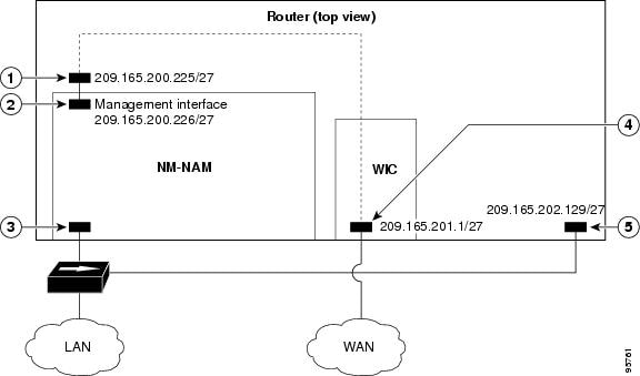
Figure 8 shows the topology used in the example, and the following sections show the router and NAM configurations:
•
•
Figure 8 Sample Topology: NAM Management Interface Is Internal and Analysis-Module Interface Is IP Unnumbered
CalloutAnalysis-Module interface
Router internal
Internal NAM interface (management)
NM-NAM internal
External NAM interface
NM-NAM faceplate
Serial interface
WAN interface card (WIC)
Fast Ethernet interface
Router rear panel
Router Configuration (Cisco IOS Software)
!ip cef!ip route 209.165.200.226 255.255.255.224 analysis-module 2/0!interface FastEthernet0/0ip address 209.165.200.225 255.255.255.224ip route-cache flowspeed autofull-duplexno mop enabledno shutdown!interface Serial 0/0encapsulation pppip address 209.165.201.1 255.255.255.224analysis-module monitoringno shutdown!interface analysis-module 2/0ip unnumbered FastEthernet0/0no shutdownhold-queue 60 out!NAM Configuration (NAM Software)
!ip address 209.165.200.226 255.255.255.224!ip host "nam1"!ip domain "cisco.com"!ip gateway 209.165.200.225!ip broadcast 10.255.255.255!ip nameserver 172.16.201.29!ip interface internal!ip http server enable!exsession on!NAM Management Interface Is External and Analysis-Module Interface Is IP Unnumbered: Example
In this configuration example:
•
•
•
•
•
•
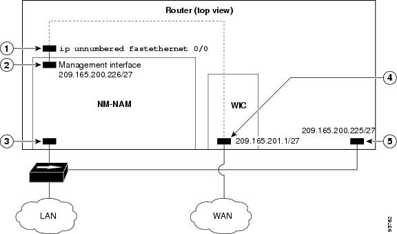
Figure 9 shows the topology used in the example, and the following sections show the router and NAM configurations:
•
•
Figure 9 Sample Topology: NAM Management Interface Is External and Analysis-Module Interface Is IP Unnumbered
CalloutAnalysis-Module interface
Router internal
Internal NAM interface
NM-NAM internal
External NAM interface (management)
NM-NAM faceplate
Loopback interface
Router internal
Serial interface
WAN interface card (WIC)
Fast Ethernet interface
Router rear panel
Router Configuration (Cisco IOS Software)
!ip cef!interface loopback 0ip address 10.1.1.1 255.255.255.0!interface FastEthernet0/0ip address 209.165.201.1 255.255.255.224ip route-cache flowspeed autofull-duplexno mop enabledno shutdown!interface Serial 0/0encapsulation pppip address 209.165.202.129 255.255.255.224analysis-module monitoringno shutdown!interface analysis-module 3/0ip unnumbered loopback 0hold-queue 60 outno shutdown!NAM Configuration (NAM software)
!ip address 209.165.201.2 255.255.255.224!ip host "nam1"!ip domain "cisco.com"!ip gateway 209.165.201.1!ip broadcast 10.255.255.255!ip nameserver 209.165.201.29!ip interface external!ip http server enable!exsession on!Additional References
The following sections provide references related to the Network Analysis Module (NM-NAM) feature.
Related Documents
Compatibility matrixes for NAM software releases, Cisco IOS releases, and platforms
Links to software downloads, product documentation, and technical documentation, including NAM software release notes, user guide, and command reference
Installing and cabling network modules
Safety and compliance
Cisco Network Modules and Interface Cards Regulatory Compliance and Safety Information
Cisco IOS interface commands: complete command syntax, command mode, command history, defaults, usage guidelines, and examples
Cisco IOS Interface and Hardware Component Command Reference
Router documentation
IP unnumbered interfaces
Authentication, authorization, and accounting (AAA)
Standards
No new or modified standards are supported by this feature, and support for existing standards has not been modified by this feature.
—
MIBs
RFCs
Technical Assistance
Command Reference
The following new commands are pertinent to this feature. To see the command pages for these commands and other commands used with this feature, go to the Cisco IOS Master Commands List, Release 12.4, at http://www.cisco.com/univercd/cc/td/doc/product/software/ios124/124mindx/
124index.htm.•
•
•
•
•
•
•
•
•
Glossary
AAA—authentication, authorization, and accounting. Pronounced "triple a."
access list—A list kept by routers to control access to or from the router for a number of services (for example, to prevent packets with a certain IP address from leaving a particular interface on the router).
CEF—Cisco Express Forwarding.
DSMON—Differentiated Services Monitoring.
flooding—Traffic passing technique used by switches and bridges in which traffic received on an interface is sent out all the interfaces of that device except the interface on which the information was received originally.
GRE—generic routing encapsulation. Tunneling protocol developed by Cisco that can encapsulate a wide variety of protocol packet types inside IP tunnels, creating a virtual point-to-point link to Cisco routers at remote points over an IP internetwork. By connecting multiprotocol subnetworks in a single-protocol backbone environment, IP tunneling using GRE allows network expansion across a single-protocol backbone environment.
GUI—graphical user interface. A user environment that uses pictorial as well as textual representations of the input and the output of applications and the hierarchical or other data structure in which information is stored. Such conventions as buttons, icons, and windows are typical, and many actions are performed using a pointing device (such as a mouse). Microsoft Windows and the Apple Macintosh are prominent examples of platforms using a GUI.
IP multicast—Routing technique that allows IP traffic to be propagated from one source to a number of destinations or from many sources to many destinations. Rather than sending one packet to each destination, one packet is sent to a multicast group identified by a single IP destination group address.
MIB—Management Information Base. Database of network management information that is used and maintained by a network management protocol, such as SNMP or Common Management Information Protocol (CMIP). The value of a MIB object can be changed or retrieved using SNMP or CMIP commands, usually through a GUI network management system. MIB objects are organized in a tree structure that includes public (standard) and private (proprietary) branches.
NAT—Network Address Translation. Mechanism for reducing the need for globally unique IP addresses. NAT allows an organization with addresses that are not globally unique to connect to the Internet by translating those addresses into globally routable address space. Also known as Network Address Translator.
NetFlow—A feature of some routers that allows them to categorize incoming packets into flows. Because packets in a flow often can be treated in the same way, this classification can be used to bypass some of the work of the router and accelerate its switching operation.
PCI—Peripheral Component Interconnect. An industry local bus standard.
QoS—quality of service. Cisco IOS QoS technology lets complex networks control and predictably service a variety of networked applications and traffic types.
RMON—remote monitoring. MIB agent specification described in RFC 1271 that defines functions for the remote monitoring of networked devices. The RMON specification provides numerous monitoring, problem detection, and reporting capabilities.
SNMP—Simple Network Management Protocol. Network management protocol used almost exclusively in TCP/IP networks. SNMP provides a means to monitor and control network devices, and to manage configurations, statistics collection, performance, and security. SNMPv2c supports centralized and distributed network management strategies and includes improvements in the Structure of Management Information (SMI), protocol operations, management architecture, and security. SNMPv3 provides secure access to devices by a combination of authenticating and encrypting packets over the network.
SSH—Secure Shell Protocol. A protocol that provides a secure remote connection to a router through a Transmission Control Protocol (TCP) application.
UDP—User Datagram Protocol. Connectionless transport layer protocol in the TCP/IP protocol stack. UDP is a simple protocol that exchanges datagrams without acknowledgments or guaranteed delivery, requiring that error processing and retransmission be handled by other protocols. UDP is defined in RFC 768.
VoIP—Voice over IP. The capability to carry normal telephony-style voice over an IP-based Internet with POTS-like functionality, reliability, and voice quality. VoIP enables a router to carry voice traffic (for example, telephone calls and faxes) over an IP network. In VoIP, the digital signal processor (DSP) segments the voice signal into frames, which then are coupled in groups of two and stored in voice packets. These voice packets are transported using IP in compliance with ITU-T specification H.323.
Note

Any Internet Protocol (IP) addresses used in this document are not intended to be actual addresses. Any examples, command display output, and figures included in the document are shown for illustrative purposes only. Any use of actual IP addresses in illustrative content is unintentional and coincidental.
© 2007 Cisco Systems, Inc. All rights reserved.
 Feedback