IEEE 802.1Q Tunneling (QinQ) and L2PT on L2 Ports
Available Languages
Table Of Contents
IEEE 802.1Q Tunneling (QnQ) and L2PT on L2 Ports
Prerequisites for IEEE 802.1Q Tunneling (QnQ) and L2PT on L2 ports
Restrictions for IEEE 802.1Q Tunneling (QnQ) and L2PT on L2 ports
Information About IEEE 802.1Q Tunneling (QnQ) and L2PT on L2 ports
Benefits of IEEE 802.1Q Tunneling (QnQ) and L2PT on L2 ports
How to Implement IEEE 802.1Q Tunneling (QnQ) and L2PT on L2 ports
Configuring IEEE 802.1Q Tunneling (QnQ) and L2PT on L2 ports
Configuration Examples for IEEE 802.1Q Tunneling (QnQ) and L2PT on L2 ports
Example: EoMPLS static Pseudowires under SVI (VLAN) Interface
Feature Information for IEEE 802.1Q Tunneling (QnQ) and L2PT on L2 ports
IEEE 802.1Q Tunneling (QnQ) and L2PT on L2 Ports
Revised: November 11, 2011, OL-20468-01First Published: November 11, 2011Last Updated: November 11, 2011This feature provides Layer 2 Tunneling support for QnQ and Layer 2 Protocol Tunneling (L2PT) on Integrated Services Router Generation 2 (ISR G2). User interface will be aligned to the service provider module or switch to support QnQ and L2PT on ISR G2 Layer 2 Port. This enables service providers to run Layer 2 Ethernet services and provide transparent LAN services over a metropolitan Ethernet infrastructure to customers.
To achieve this, the following features are implemented:
•
L2PT on Layer 2 ports
•
•
•
•
•

Note
Finding Feature Information
Your software release may not support all the features documented in this module. For the latest feature information and caveats, see the release notes for your platform and software release. To find information about the features documented in this module, and to see a list of the releases in which each feature is supported, see the "Information About IEEE 802.1Q Tunneling (QnQ) and L2PT on L2 ports" section.
Use Cisco Feature Navigator to find information about platform support and Cisco software image support. To access Cisco Feature Navigator, go to http://www.cisco.com/go/cfn. An account on Cisco.com is not required.
Contents
•
•
•
•
•
•
Note
Prerequisites for IEEE 802.1Q Tunneling (QnQ) and L2PT on L2 ports
•
•
–
–
–
–
–
•
Restrictions for IEEE 802.1Q Tunneling (QnQ) and L2PT on L2 ports
•
•
Information About IEEE 802.1Q Tunneling (QnQ) and L2PT on L2 ports
•
Benefits of IEEE 802.1Q Tunneling (QnQ) and L2PT on L2 ports
Simpler Architecture and Lower Operational Cost
Today, Layer 2 Ethernet services are offered as a specific service based on pure Ethernet access. End-to-end Ethernet services have simpler architechture with lower operational cost.
Scalability
The objectives of these enhancements are to enable the service providers to extend Layer 2 Ethernet services over any access technology and provide transparent LAN services over a metropolitan Ethernet infrastructure to customers.
Because QnQ uses a double-tagged frame technique, it doubles the theoretical frame size limit of the IEEE 802.1Q, which is sufficient to accomodate network growth for several years.
Efficiency
These enhancements will also enable service providers to run both IP and non-IP traffic under the same Customer Premises Equipment (CPE).
How to Implement IEEE 802.1Q Tunneling (QnQ) and L2PT on L2 ports
•
Configuring IEEE 802.1Q Tunneling (QnQ) and L2PT on L2 ports
Service providers offer different specifications for VLAN IDs and the number of VLANs to be supported for each business customers. To provide these services, QnQ and L2PT must be implemented on ISR G2 Layer 2 port. These features are already implemeneted on multiple Cisco products but the code base and user interface may vary.
QnQ is an amendment to IEEE standard IEEE 802.1Q. It used to only allow a single VLAN header to be inserted into an Ethernet frame but now it can allow multiple VLAN headers.
To configure QnQ and Layer 2 Protocol Tunneling, perform the following steps:
For more information about QnQ, see the "Understanding IEEE 802.1Q Tunneling" section in Catalyst 3550 Multilayer Switch Software Configuration Guide.
Customers at different sites connected across a service-provider network need to use various Layer 2 protocols to scale their topologies to include all remote sites, as well as local sites. Configuring Layer 2 Protocol Tunneling (L2PT) destination MAC address to default to Cisco L2PT MAC is the solution.
For more information about L2PT, see the "Understanding Layer 2 Protocol Tunneling" section in Catalyst 3550 Multilayer Switch Software Configuration Guide.
Prerequisites
•
•
•
•
•
Note
Restrictions
•
•
•
•
•
•
•
•
•
•
•
•
SUMMARY STEPS
1.
2.
3.
4.
or
switchport mode dot1q-tunnel5.
6.
7.
8.
DETAILED STEPS
Configuration Examples for IEEE 802.1Q Tunneling (QnQ) and L2PT on L2 ports
Example: EoMPLS static Pseudowires under SVI (VLAN) Interface
The following example shows the relevant configuration for EoMPLS under SVI for a single PE:
mpls label range 2000 16000 static 16 1999mpls label protocol ldp!pseudowire-class testencapsulation mplsprotocol none!interface Loopback1description *** Loopback Interface ***ip address 1.1.1.1 255.255.255.255!interface FastEthernet3description * PW Attachment Circuit *switchport access vlan 100switchport mode dot1q-tunnel!interface Vlan100description **L2VPN Customer**no ip addressxconnect 1.1.1.2 100 encapsulation mpls manual pw-class testmpls label 100 150!mpls ldp router-id Loopback1!endExample: EoMPLS
The following example shows how to configure EoMPLS over GRE:
Sample Topology
Figure 1
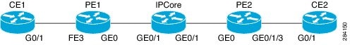
EoMPLS Over GRE Topology
CE1 Configuration
CE1# show running-config interface gigabitEthernet 0/1Building configuration...Current configuration : 123 bytes!interface GigabitEthernet0/1ip address 30.1.1.1 255.255.255.0duplex autospeed autoendCE1#PE1 Configuration
Current configuration : 4000 bytes!! Last configuration change at 14:59:33 PDT Wed Aug 10 2011! NVRAM config last updated at 15:00:18 PDT Wed Aug 10 2011! NVRAM config last updated at 15:00:18 PDT Wed Aug 10 2011version 15.2service timestamps debug datetime msec localtime show-timezoneservice timestamps log datetime msec localtime show-timezoneno service password-encryption!hostname uu1-890!boot-start-markerboot system flash:c890-universalk9-mz-rd8boot system flash:c890-universalk9-mz.152-1.3.Tboot-end-marker!no logging console!no aaa new-model!memory-size iomem 10clock timezone PDT -7 0service-module wlan-ap 0 bootimage autonomouscrypto pki token default removal timeout 0!ip auth-proxy max-login-attempts 5ip admission max-login-attempts 5!ip cefno ipv6 cef!multilink bundle-name authenticatedmpls label range 2000 16000 static 16 1999mpls label protocol ldp!!!license udi pid CISCO891W-AGN-A-K9 sn FHK1302218Wlicense accept end user agreement!!archivelog confighidekeys!pseudowire-class testencapsulation mplsprotocol none!interface Loopback1description *** Loopback Interface ***ip address 1.1.1.1 255.255.255.255!interface Tunnel1description *** Tunnel Interface to PE2 ***ip unnumbered Loopback1load-interval 30mpls iptunnel source GigabitEthernet0tunnel destination 22.0.0.2!interface FastEthernet0no ip address!interface FastEthernet1no ip address!interface FastEthernet2no ip address!interface FastEthernet3description * PW Attachment Circuit, connected to CE1 *switchport access vlan 100switchport mode dot1q-tunnelno ip addressload-interval 30l2protocol-tunnel cdpl2protocol-tunnel lldpl2protocol-tunnel stpl2protocol-tunnel vtpl2protocol-tunnel point-to-point udldno cdp enable!interface FastEthernet4no ip address!interface FastEthernet5no ip address!interface FastEthernet6no ip address!interface FastEthernet7no ip address!interface FastEthernet8no ip addressduplex autospeed auto!interface GigabitEthernet0ip address 21.0.0.1 255.255.255.0duplex autospeed auto!interface wlan-ap0description Service module interface to manage the embedded APno ip addressarp timeout 0!interface Wlan-GigabitEthernet0description Internal switch interface connecting to the embedded APno ip address!interface Vlan1ip address no ip address!interface Vlan100description **L2VPN Customer**no ip addressload-interval 30xconnect 1.1.1.2 100 encapsulation mpls manual pw-class testmpls label 100 150!interface Async1no ip addressencapsulation slip!router ospf 1network 1.1.1.1 0.0.0.0 area 0network 21.0.0.0 0.0.0.255 area 0!ip forward-protocol nd!no ip http serverno ip http secure-serverip route 1.1.1.2 255.255.255.255 Tunnel1!mpls ldp router-id Loopback1!control-plane!line con 0exec-timeout 0 0line 1modem InOutstopbits 1speed 115200flowcontrol hardwareline 2no activation-characterno exectransport preferred nonetransport input alltransport output pad telnet rlogin udptn sshline aux 0line vty 0 4logintransport input all!scheduler max-task-time 5000!enduu1-890#IP Core Configuration
interface GigabitEthernet0/0ip address 22.0.0.1 255.255.255.0duplex autospeed auto!interface GigabitEthernet0/1ip address 21.0.0.2 255.255.255.0load-interval 30duplex autospeed auto!router ospf 1network 21.0.0.0 0.0.0.255 area 0network 22.0.0.0 0.0.0.255 area 0!ip forward-protocol nd!no ip http serverno ip http secure-server!control-plane!line con 0exec-timeout 0 0line aux 0line 2no activation-characterno exectransport preferred nonetransport input alltransport output lat pad telnet rlogin lapb-ta mop udptn v120 sshstopbits 1line vty 0 4logintransport input all!scheduler allocate 20000 1000!endipcore#PE2 Configuration
uu2-2951# show running-configBuilding configuration...Current configuration : 3534 bytes!! Last configuration change at 14:49:05 PDT Wed Aug 10 2011! NVRAM config last updated at 14:49:22 PDT Wed Aug 10 2011! NVRAM config last updated at 14:49:22 PDT Wed Aug 10 2011version 15.2service timestamps debug datetime msecservice timestamps log datetime msecno service password-encryptionservice internal!hostname uu2-2951!boot-start-markerboot system flash0:c2951-universalk9-mz.SSA-rd8boot-end-marker!no logging console!no aaa new-model!clock timezone PDT -7 0!crypto pki token default removal timeout 0!no ipv6 cefip auth-proxy max-login-attempts 5ip admission max-login-attempts 5!ip inspect WAAS flush-timeout 10ip cef!multilink bundle-name authenticated!mpls label range 2000 16000 static 16 1999mpls label protocol ldp!voice-card 0!license udi pid CISCO2951/K9 sn FHK1441F0WWlicense boot module c2951 technology-package securityk9license boot module c2951 technology-package uck9license boot module c2951 technology-package datak9!redundancy!pseudowire-class testencapsulation mplsprotocol none!interface Loopback1description ***loopback interface***ip address 1.1.1.2 255.255.255.255!interface Tunnel1description ***Tunnel Int to PE1***bandwidth 10ip unnumbered Loopback1load-interval 30mpls iptunnel source GigabitEthernet0/0tunnel destination 21.0.0.1!interface Embedded-Service-Engine0/0no ip addressshutdown!interface GigabitEthernet0/0description *** BB interface ***ip address 22.0.0.2 255.255.255.0load-interval 30duplex autospeed auto!interface GigabitEthernet0/1no ip addressshutdownduplex autospeed autono keepalive!interface GigabitEthernet0/2ip address no ip addressduplex autospeed auto!interface GigabitEthernet0/1/0no ip address!interface GigabitEthernet0/1/1no ip address!interface GigabitEthernet0/1/2no ip address!interface GigabitEthernet0/1/3description * PW Attachment Circuit, connected to CE1switchport access vlan 100no ip addressl2protocol-tunnel cdpl2protocol-tunnel lldpl2protocol-tunnel stpl2protocol-tunnel vtpl2protocol-tunnel point-to-point udldno cdp enable!interface Vlan1no ip address!interface Vlan100description **L2VPN Customer**no ip addressload-interval 30mpls label protocol ldpxconnect 1.1.1.1 100 encapsulation mpls manual pw-class testmpls label 150 100!router ospf 1network 1.1.1.2 0.0.0.0 area 0network 22.0.0.0 0.0.0.255 area 0!ip forward-protocol nd!no ip http serverno ip http secure-server!ip route 1.1.1.1 255.255.255.255 Tunnel1!mpls ldp router-id Loopback1control-plane!gatekeepershutdown!line con 0exec-timeout 0 0line aux 0line 2no activation-characterno exectransport preferred nonetransport input alltransport output pad telnet rlogin lapb-ta mop udptn v120 sshstopbits 1line vty 0 4logintransport input all!scheduler allocate 20000 1000!endCE2 Configuration
CE2# show running-config interface gigabitEthernet 0/1Building configuration...Current configuration : 150 bytes!interface GigabitEthernet0/1ip address 30.1.1.2 255.255.255.0load-interval 30duplex autospeed autoendWhere to Go Next
For more information about Cisco G.SHDSL Ethernet first mile, see Configuring Cisco G.SHDSL EFM HWICs in Cisco Routers.
Additional References
Related Documents
Cisco IOS commands
Cisco Integrated Services Routers
Switch Virtual Interface for Cisco Integrated Services Routers
IEEE 802.1Q tunneling and L2PT
Catalyst 3550 Multilayer Switch Software Configuration Guide
EoMPLS over GRE
Standards
—
No new or modified standards are supported by this feature, and support for existing standards has not been modified by this feature.
MIBs
—
No new or modified MIBs are supported by this feature, and support for existing MIBs has not been modified by this feature.
RFCs
—
No new or modified RFCs are supported by this feature, and support for existing RFCs has not been modified by this feature.
Technical Assistance
Feature Information for IEEE 802.1Q Tunneling (QnQ) and L2PT on L2 ports
Use Cisco Feature Navigator to find information about platform support and software image support. Cisco Feature Navigator enables you to determine which software images support a specific software release, feature set, or platform. To access Cisco Feature Navigator, go to http://www.cisco.com/go/cfn. An account on Cisco.com is not required.
Note
Glossary
ACLs—access control lists
CDP—Cisco Discovery Protocol
DTP—Dynamic Trunking Protocol
L2PT—Layer 2 Protocol Tunneling
PAgP—Port Aggregation Protocol
VTP—VLAN Trunking Protocol
Cisco and the Cisco logo are trademarks or registered trademarks of Cisco and/or its affiliates in the U.S. and other countries. To view a list of Cisco trademarks, go to this URL: www.cisco.com/go/trademarks. Third-party trademarks mentioned are the property of their respective owners. The use of the word partner does not imply a partnership relationship between Cisco and any other company. (1110R)
Any Internet Protocol (IP) addresses and phone numbers used in this document are not intended to be actual addresses and phone numbers. Any examples, command display output, network topology diagrams, and other figures included in the document are shown for illustrative purposes only. Any use of actual IP addresses or phone numbers in illustrative content is unintentional and coincidental.
© 2011 Cisco Systems, Inc. All rights reserved.
 Feedback