Hardware Installation Guide for Cisco 4000 Series Integrated Services Routers
Bias-Free Language
The documentation set for this product strives to use bias-free language. For the purposes of this documentation set, bias-free is defined as language that does not imply discrimination based on age, disability, gender, racial identity, ethnic identity, sexual orientation, socioeconomic status, and intersectionality. Exceptions may be present in the documentation due to language that is hardcoded in the user interfaces of the product software, language used based on RFP documentation, or language that is used by a referenced third-party product. Learn more about how Cisco is using Inclusive Language.
- Updated:
- September 10, 2014
Chapter: Install and Connect Cisco 4000 Series ISRs
Install and Connect Cisco 4000 Series ISRs
This chapter describes how to install and connect Cisco 4000 Series Integrated Services Routers (ISRs) to LAN, WAN, and Voice networks. The following sections provide technical details.
- Install the Router
- Chassis Grounding
- Connect Power
- Connect to Console Terminal or Modem
- Install Cisco Microsoft Windows USB Device Driver
- Uninstall Cisco Microsoft Windows USB Driver
- Connect WAN, LAN, and Voice Interfaces

Warning![]() To reduce the risk of electric shock, secure the modules with provided screws. Statement 347
To reduce the risk of electric shock, secure the modules with provided screws. Statement 347
Warning![]() To reduce the risk of electric shock, the chassis of this equipment needs to be connected to permanent earth ground during normal use. Statement CS-0445
To reduce the risk of electric shock, the chassis of this equipment needs to be connected to permanent earth ground during normal use. Statement CS-0445
Warning![]() To reduce risk of electric shock and fire, a readily accessible two-poled disconnect device must be incorporated in the fixed wiring. Statement 1022
To reduce risk of electric shock and fire, a readily accessible two-poled disconnect device must be incorporated in the fixed wiring. Statement 1022
Warning![]() To see translations of the warnings that appear in this publication, see the Regulatory Compliance and Safety Information for the Cisco 4000 Series ISRs document. Only trained and qualified personnel should be allowed to install, replace, or service this equipment. Statement 1030
To see translations of the warnings that appear in this publication, see the Regulatory Compliance and Safety Information for the Cisco 4000 Series ISRs document. Only trained and qualified personnel should be allowed to install, replace, or service this equipment. Statement 1030
Warning![]() This unit might have more than one power supply connection. All connections must be removed to de-energize the unit. Statement 1028
This unit might have more than one power supply connection. All connections must be removed to de-energize the unit. Statement 1028
Warning![]() Blank faceplates and cover panels serve three important functions: they prevent exposure to hazardous voltages and currents inside the chassis; they contain electromagnetic interference (EMI) that might disrupt other equipment; and they direct the flow of cooling air through the chassis. Do not operate the system unless all cards, faceplates, front covers, and rear covers are in place. Statement 1029
Blank faceplates and cover panels serve three important functions: they prevent exposure to hazardous voltages and currents inside the chassis; they contain electromagnetic interference (EMI) that might disrupt other equipment; and they direct the flow of cooling air through the chassis. Do not operate the system unless all cards, faceplates, front covers, and rear covers are in place. Statement 1029
Warning![]() Hazardous network voltages are present in WAN ports regardless of whether power to the unit is OFF or ON. To avoid electric shock, use caution when working near WAN ports. When detaching cables, detach the end away from the unit first. Statement 1026
Hazardous network voltages are present in WAN ports regardless of whether power to the unit is OFF or ON. To avoid electric shock, use caution when working near WAN ports. When detaching cables, detach the end away from the unit first. Statement 1026
Warning![]() This equipment must be grounded. Never defeat the ground conductor or operate the equipment in the absence of a suitably installed ground conductor. Contact the appropriate electrical inspection authority or an electrician if you are uncertain that suitable grounding is available. Statement 1024
This equipment must be grounded. Never defeat the ground conductor or operate the equipment in the absence of a suitably installed ground conductor. Contact the appropriate electrical inspection authority or an electrician if you are uncertain that suitable grounding is available. Statement 1024
Warning![]() Before opening the unit, disconnect the telephone-network cables to avoid contact with telephone-network voltages. Statement 1041
Before opening the unit, disconnect the telephone-network cables to avoid contact with telephone-network voltages. Statement 1041
Warning![]() Do not use this product near water; for example, near a bath tub, wash bowl, kitchen sink or laundry tub, in a wet basement, or near a swimming pool. Statement 1035
Do not use this product near water; for example, near a bath tub, wash bowl, kitchen sink or laundry tub, in a wet basement, or near a swimming pool. Statement 1035
Warning![]() Never install telephone jacks in wet locations unless the jack is specifically designed for wet locations. Statement 1036
Never install telephone jacks in wet locations unless the jack is specifically designed for wet locations. Statement 1036
Warning![]() Never touch uninsulated telephone wires or terminals unless the telephone line has been disconnected at the network interface. Statement 1037
Never touch uninsulated telephone wires or terminals unless the telephone line has been disconnected at the network interface. Statement 1037
Warning![]() Avoid using a telephone (other than a cordless type) during an electrical storm. There may be a remote risk of electric shock from lightning. Statement 1038
Avoid using a telephone (other than a cordless type) during an electrical storm. There may be a remote risk of electric shock from lightning. Statement 1038
Warning![]() To report a gas leak, do not use a telephone in the vicinity of the leak. Statement 1039
To report a gas leak, do not use a telephone in the vicinity of the leak. Statement 1039
Warning![]() This unit is intended for installation in restricted access areas. A restricted access area can be accessed only through the use of a special tool, lock and key, or other means of security. Statement 1017
This unit is intended for installation in restricted access areas. A restricted access area can be accessed only through the use of a special tool, lock and key, or other means of security. Statement 1017
Warning![]() Blank faceplates and cover panels serve three important functions: they prevent exposure to hazardous voltages and currents inside the chassis; they contain electromagnetic interference (EMI) that might disrupt other equipment; and they direct the flow of cooling air through the chassis. Do not operate the system unless all cards, faceplates, front covers, and rear covers are in place.
Blank faceplates and cover panels serve three important functions: they prevent exposure to hazardous voltages and currents inside the chassis; they contain electromagnetic interference (EMI) that might disrupt other equipment; and they direct the flow of cooling air through the chassis. Do not operate the system unless all cards, faceplates, front covers, and rear covers are in place.
Statement 1029
Warning![]() The covers are an integral part of the safety design of the product. Do not operate the unit without the covers installed. Statement 1077
The covers are an integral part of the safety design of the product. Do not operate the unit without the covers installed. Statement 1077
Warning![]() Instructed person is someone who has been instructed and trained by a skilled person and takes the necessary precautions when working with equipment. Skilled person/Qualified personnel is someone who has training or experience in the equipment technology and understand potential hazards when working with equipment. Statement 1089
Instructed person is someone who has been instructed and trained by a skilled person and takes the necessary precautions when working with equipment. Skilled person/Qualified personnel is someone who has training or experience in the equipment technology and understand potential hazards when working with equipment. Statement 1089
Warning![]() Only skilled person should be allowed to install, replace, or service this equipment. Refer to statement 1089 for description of skilled person. Statement 1090
Only skilled person should be allowed to install, replace, or service this equipment. Refer to statement 1089 for description of skilled person. Statement 1090
Warning![]() Only instructed person or skilled person should be allowed to install, replace, or service this equipment. Refer to statement 1089 for description of skilled person. Statement 1091
Only instructed person or skilled person should be allowed to install, replace, or service this equipment. Refer to statement 1089 for description of skilled person. Statement 1091
Warning![]() This equipment must be grounded.To reduce the risk of electric shock, the power cord, plug or combination must be connected to a properly grounded electrode, outlet or terminal. Statement 1252—Equipment Grounding
This equipment must be grounded.To reduce the risk of electric shock, the power cord, plug or combination must be connected to a properly grounded electrode, outlet or terminal. Statement 1252—Equipment Grounding
Before You Begin
Before installing and connecting a Cisco 4000 Series Integrated Services Router, read the safety warnings and gather the following tools and equipment.
- ESD-preventive cord and wrist strap
- Number 2 Phillips screwdriver
- Flat-blade screwdrivers: small, 3/16-in. (4 to 5 mm) and medium, 1/4-in. (6 to 7 mm)
–![]() To install or remove modules
To install or remove modules
–![]() To remove the cover, if you are upgrading memory or other components
To remove the cover, if you are upgrading memory or other components
–![]() AWG 6 (13 mm) wire for NEBS-compliant chassis grounding
AWG 6 (13 mm) wire for NEBS-compliant chassis grounding
–![]() AWG 14 (2 mm) or larger wire for NEC-compliant chassis grounding
AWG 14 (2 mm) or larger wire for NEC-compliant chassis grounding
–![]() AWG 18 (1 mm) or larger wire for EN/IEC 60950-compliant chassis grounding
AWG 18 (1 mm) or larger wire for EN/IEC 60950-compliant chassis grounding
- For NEC-compliant grounding, an appropriate user-supplied ring terminal, with an inner diameter of 1/4 in. (5 to 7 mm)
In addition, depending on the type of modules you plan to use, you might need the following equipment to connect a port to an external network:

Note![]() For more information on cable specifications, see the Cisco Modular Access Router Cable Specifications document at cisco.com.
For more information on cable specifications, see the Cisco Modular Access Router Cable Specifications document at cisco.com.
- Ethernet hub or PC with a network interface card for connection to an Ethernet (LAN) port.
- Console terminal (an ASCII terminal or a PC running HyperTerminal or similar terminal emulation software) configured for 9600 baud, 8 data bits, 1 stop bit, no flow control, and no parity.
- Modem for connection to the auxiliary port for remote administrative access (optional).
- Data service unit (DSU) or channel service unit/data service unit (CSU/DSU) as appropriate for serial interfaces.
- External CSU for any CT1/PRI modules without a built-in CSU.
Also, you need to have access to the following:
Use the USB or RJ-45 console port on the router to access the Cisco Internet Operating System (IOS-XE) command line interface (CLI) on the router and to perform configuration tasks. A terminal emulation program is required to establish communication between the router and a PC. See the “Connect to Console Terminal or Modem” section for instructions.
Note![]() A Microsoft Windows USB driver must be installed before you establish physical connectivity between the router and the PC.
A Microsoft Windows USB driver must be installed before you establish physical connectivity between the router and the PC.
The routers have built in ports and new slots. The new slots accommodate new modules and interface cards; SM-Xs, NIMs, ISCs, PVDM4s, and the Cisco E-Series Server modules. See the “Slots, Subslots (Bay), Ports, and Interfaces in Cisco 4000 Series ISRs” section for slot and port numbering.
To install features on the router, you must purchase a software package. See the “Licensing” section of the Software Configuration Guide for the Cisco 4400 and Cisco 4300 Series ISRs.
Unpack the Router
Do not unpack the router until you are ready to install it. If the final installation site is not ready as yet, keep the chassis in its shipping container to prevent accidental damage. When you are ready to install the router, unpack it.
The router, accessory kit, publications, and any optional equipment you ordered may be shipped in more than one container. When you unpack the containers, check the packing list to ensure that you received all of the items on the list.
Install the Router
If you need to install Network Interface Modules (NIMs), Service Modules (SMs), and Field-Replaceable Units (FRUs), you can install them either before or after you install the router. Ideally, you install modules when you have the best access to the back panel of the router. Internal modules and FRUs, such as SMs, NIMs or Packet Voice Digital Signal Processor Module (PVDM4s), Compact Flash Cards, and fan trays should be installed before rack-mounting.
You can install the Cisco 4000 Series Integrated Services Routers in one of the following ways:
- Set the router chassis on a desktop
- Attach the router chassis to the wall (Cisco 4461, 4451, and 4351 ISRs do not support wall mounting.)
- Mount the router chassis in a rack
Warning![]() Before working on a system that has an On/Off switch, turn OFF the power and unplug the power cord. Statement 1.
Before working on a system that has an On/Off switch, turn OFF the power and unplug the power cord. Statement 1.

Set Chassis on Desktop
You can place the router on a desktop, bench top, or shelf.
Note![]() Do not set the chassis in an area where high acoustic noise can be an issue.
Do not set the chassis in an area where high acoustic noise can be an issue.
Warning![]() To prevent personal injury or damage to the chassis, never attempt to lift or tilt the chassis using the handles on modules (such as power supplies, fans, or cards); these types of handles are not designed to support the weight of the unit. Statement 1032.
To prevent personal injury or damage to the chassis, never attempt to lift or tilt the chassis using the handles on modules (such as power supplies, fans, or cards); these types of handles are not designed to support the weight of the unit. Statement 1032.
10 pounds on top could damage the chassis.
After the router is installed, you must connect the chassis to a reliable earth ground. For the chassis ground connection procedures, see the “Chassis Grounding” section.
Attach Chassis to Wall or Mount Chassis in Rack
The tasks that you perform for attaching the router chassis to the wall, or for mounting it in a rack, are based on the specific model of the Cisco 4000 Series Integrated Service Router.
See the relevant installation sub-section for your specific router in the Cisco 4000 Series ISRs:
Install Cisco 4400 or 4300 ISR
This section describes the installation procedure that is common for all Cisco 4400 and 4300 Series ISRs.
Note![]() For illustration purposes, we have used images of Cisco 4400 Series ISRs in all figures. You cannot wall mount the Cisco 4461, 4451, and 4351 ISR as these routers do not support wall mounting.
For illustration purposes, we have used images of Cisco 4400 Series ISRs in all figures. You cannot wall mount the Cisco 4461, 4451, and 4351 ISR as these routers do not support wall mounting.
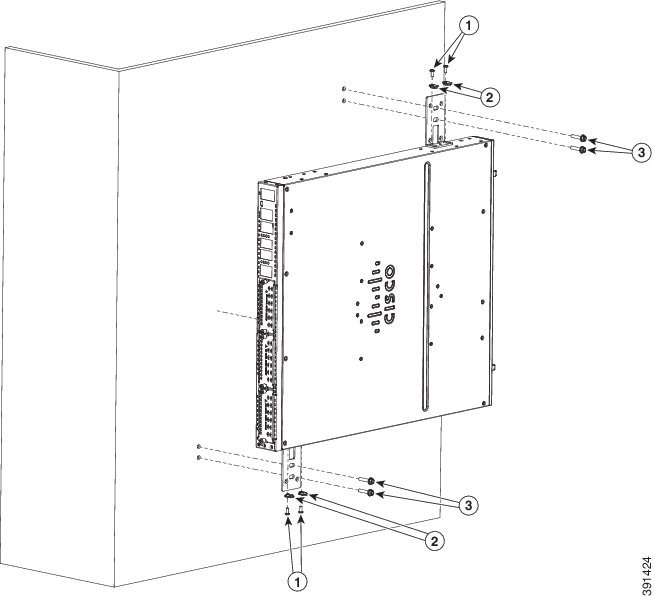
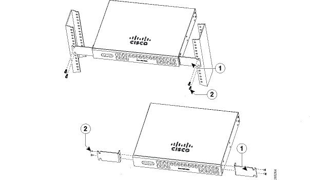
Attach Cisco 4400 or 4300 ISR Chassis to Wall
Step 1![]() Attach the wall-mounting brackets to the router chassis as shown in Figure 3-1 using the four PHMS screws and the plastic spacers provided for each bracket.
Attach the wall-mounting brackets to the router chassis as shown in Figure 3-1 using the four PHMS screws and the plastic spacers provided for each bracket.
Figure 3-1 Bracket Installation for Wall Mounting (Cisco 4431 ISR shown)
|
|
|
||
|
|
|
Note![]() To attach to a wall stud, each bracket requires one number-10 wood screws (round- or pan-head) with number-10 washers, or two number-10 washer-head screws. The screws must be long enough to penetrate at least 1.5 inches (38.1 mm) into the supporting wood or metal wall stud.
To attach to a wall stud, each bracket requires one number-10 wood screws (round- or pan-head) with number-10 washers, or two number-10 washer-head screws. The screws must be long enough to penetrate at least 1.5 inches (38.1 mm) into the supporting wood or metal wall stud.
Note![]() For hollow-wall mounting, each bracket requires two wall anchors with washers. Wall anchors and washers must be size number 10. Route the cables so that they do not put a strain on the connectors or mounting hardware.
For hollow-wall mounting, each bracket requires two wall anchors with washers. Wall anchors and washers must be size number 10. Route the cables so that they do not put a strain on the connectors or mounting hardware.
Step 2![]() Attach the router to the wall using the brackets.
Attach the router to the wall using the brackets.
Note![]() If you prefer, you can also install the router diagonally using the other two sides.
If you prefer, you can also install the router diagonally using the other two sides.
After the router is installed, you must connect the chassis to a reliable earth ground. For the chassis ground connection procedures, see the “Chassis Grounding” section.
Mount Cisco 4400 or 4300 ISR Chassis in Rack
Warning![]() If the rack is provided with stabilizing devices, install the stabilizers before mounting or servicing the unit in the rack. Statement 1006
If the rack is provided with stabilizing devices, install the stabilizers before mounting or servicing the unit in the rack. Statement 1006
Warning![]() This equipment must be grounded. Never defeat the ground conductor or operate the equipment in the absence of a suitably installed ground conductor. Contact the appropriate electrical inspection authority or an electrician if you are uncertain that suitable grounding is available. Statement 1024
This equipment must be grounded. Never defeat the ground conductor or operate the equipment in the absence of a suitably installed ground conductor. Contact the appropriate electrical inspection authority or an electrician if you are uncertain that suitable grounding is available. Statement 1024
Warning![]() To prevent the system from overheating, do not operate it in an area that exceeds the maximum recommended ambient temperature of: 40 degrees C. Statement 1047
To prevent the system from overheating, do not operate it in an area that exceeds the maximum recommended ambient temperature of: 40 degrees C. Statement 1047
Note![]() Cisco 4461 ISR can operate in an area with an ambient temperature of 55 degrees C.
Cisco 4461 ISR can operate in an area with an ambient temperature of 55 degrees C.
Cisco 4000 Series ISRs can be installed in 19-inch (48.26-cm) EIA and 23-inch (58.42-cm) Southwestern Bell Corporation (SBC) racks. Cisco 4000 Series ISRs can also be mounted in a 600-mm ETSI rack. Use the standard brackets shipped with the router for mounting the chassis in a 19-inch EIA rack; you can order optional larger brackets for mounting the chassis in a 23-inch SBC rack.
You can mount the router in the following ways:
- Center-front mounting: Brackets attached in the center front of the chassis with only the front panel facing forward.
- Center-back mounting: Brackets attached in the center back of the chassis with only the back panel facing forward.
- Front mounting: Brackets attached at the front of the chassis with the front panel facing forward.
- Back mounting: Brackets attached at the back of the chassis with the back panel facing forward.
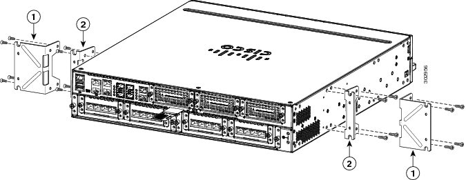
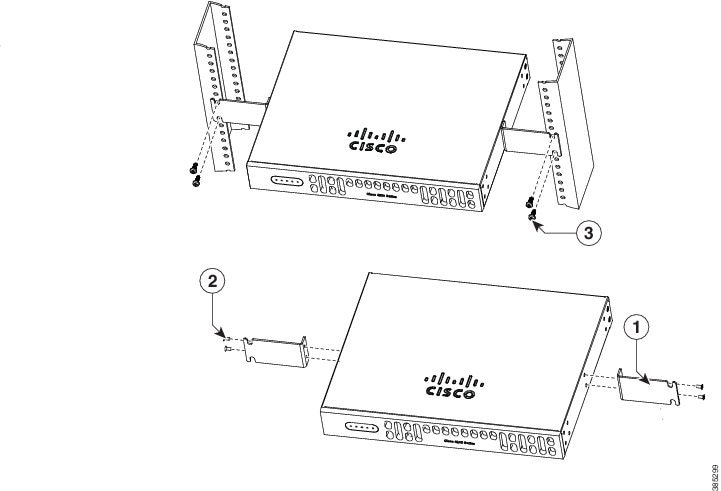
Step 1![]() Attach the mounting brackets to the router chassis as shown in Figure 3-2 through Figure 3-5, using the screws provided.
Attach the mounting brackets to the router chassis as shown in Figure 3-2 through Figure 3-5, using the screws provided.
Attach the second bracket to the opposite side of the chassis. Use a number-2 Phillips screwdriver to install the number-8 bracket screws.
Figure 3-2 Bracket Installation for Front Mounting (Cisco 4451-X ISR shown)
|
|
23-inch SBC1 brackets |
|
|
|
Figure 3-3 Bracket Installation for Center-Front Mounting (Cisco 4451-X ISR shown)
|
|
|
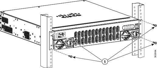
Step 2![]() Use the screws provided with the rack to install the chassis in the rack. (See Figure 3-4 and Figure 3-6.)
Use the screws provided with the rack to install the chassis in the rack. (See Figure 3-4 and Figure 3-6.)
For both the 19-inch EIA brackets and the 23-inch SBC brackets, start the lower pair of screws first, and rest the brackets on the lower screws while you insert the upper pair of screws.

Tip![]() The screw slots in the brackets are spaced to line up with every second pair of screw holes in the rack. When the correct screw holes are used, the small, threaded holes in the brackets line up with unused screw holes in the rack. If the small holes do not line up with the rack holes, you must raise or lower the brackets to the next rack hole.
The screw slots in the brackets are spaced to line up with every second pair of screw holes in the rack. When the correct screw holes are used, the small, threaded holes in the brackets line up with unused screw holes in the rack. If the small holes do not line up with the rack holes, you must raise or lower the brackets to the next rack hole.
Warning![]() To prevent personal injury or damage to the chassis, never attempt to lift or tilt the chassis using the handles on modules (such as power supplies, fans, or cards); these types of handles are not designed to support the weight of the unit. Statement 1032
To prevent personal injury or damage to the chassis, never attempt to lift or tilt the chassis using the handles on modules (such as power supplies, fans, or cards); these types of handles are not designed to support the weight of the unit. Statement 1032
Figure 3-4 Bracket Installation for Back Mounting (Cisco 4451-X ISR shown)
|
|
|
Figure 3-5 Bracket Installation for Center-Back Mounting (Cisco 4451-X ISR shown)
|
|
|
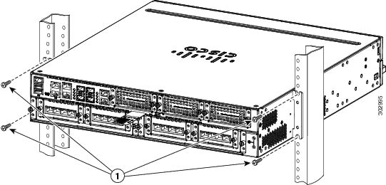
Figure 3-6 shows a typical installation in a rack.
Figure 3-6 Mounting the Chassis in a Rack (Typical)
|
|
Figure 3-7 shows an installation with a chassis rear-forward.
Figure 3-7 Mounting the Chassis in a Rack, Rear Forward (Cisco 4451-X ISR shown)
|
|
After the router is installed, you must connect the chassis to a reliable earth ground. For the chassis ground connection procedures, see the “Chassis Grounding” section.
Install Cisco 4200 Series ISR
This section describes the installation procedure that is common for all Cisco 4200 Series ISRs.
Note![]() For illustration purposes, we have used images of Cisco 4221 ISR in all figures.
For illustration purposes, we have used images of Cisco 4221 ISR in all figures.
Attach Cisco 4200 ISR Chassis to Wall
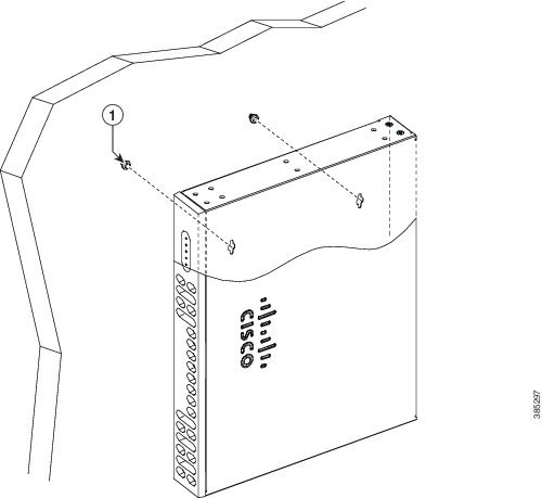
Step 1![]() Attach the wall-mounting brackets to the router chassis as shown in Step 2 using the four PHMS screws and the plastic spacers provided for each bracket.
Attach the wall-mounting brackets to the router chassis as shown in Step 2 using the four PHMS screws and the plastic spacers provided for each bracket.
Figure 3-8 Bracket Installation for Wall Mounting (Cisco 4221 ISR shown)
|
|
|
Note![]() Do not over-torque the screws. The recommended torque is 15 to 18 inch-lb (1.7 to 2.0 N-m).
Do not over-torque the screws. The recommended torque is 15 to 18 inch-lb (1.7 to 2.0 N-m).
Note![]() To attach to a wall stud, each bracket requires one number-10 wood screws (round- or pan-head) with number-10 washers, or two number-10 washer-head screws. The screws must be long enough to penetrate at least 1.5 inches (38.1 mm) into the supporting wood or metal wall stud.
To attach to a wall stud, each bracket requires one number-10 wood screws (round- or pan-head) with number-10 washers, or two number-10 washer-head screws. The screws must be long enough to penetrate at least 1.5 inches (38.1 mm) into the supporting wood or metal wall stud.
Note![]() For hollow-wall mounting, each bracket requires two wall anchors with washers. Wall anchors and washers must be size number 10. Route the cables so that they do not put a strain on the connectors or mounting hardware.
For hollow-wall mounting, each bracket requires two wall anchors with washers. Wall anchors and washers must be size number 10. Route the cables so that they do not put a strain on the connectors or mounting hardware.
Note![]() Your chassis installation must allow unrestricted airflow for chassis cooling.
Your chassis installation must allow unrestricted airflow for chassis cooling.
Step 2![]() Attach the router to the wall using the brackets.
Attach the router to the wall using the brackets.
After the router is installed, you must connect the chassis to a reliable earth ground. For the chassis ground connection procedures, see the “Chassis Grounding” section.
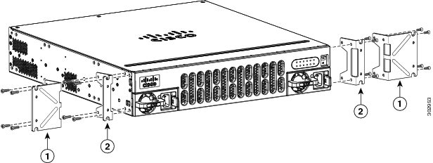
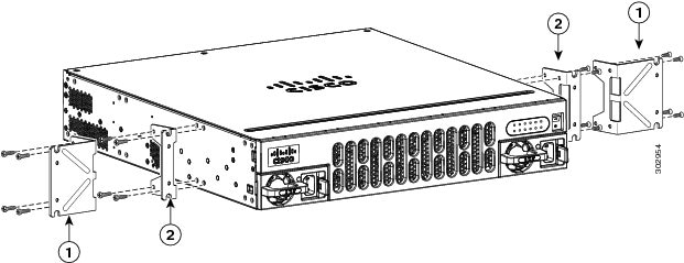
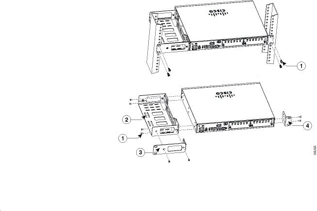
Mount Cisco 4200 ISR Chassis in Rack
Step 1![]() Attach the brackets to the router chassis (towards the front or back) as shown in Figure 3-10.
Attach the brackets to the router chassis (towards the front or back) as shown in Figure 3-10.
Figure 3-9 Bracket Installation for Front Mounting (Cisco 4221 ISR shown)
|
|
|
Step 2![]() Use the screws provided with the rack to install the chassis in the rack. (See Figure 3-10.)
Use the screws provided with the rack to install the chassis in the rack. (See Figure 3-10.)
Figure 3-10 Bracket Installation for Back Mounting
|
|
|
Warning![]() To prevent personal injury or damage to the chassis, never attempt to lift or tilt the chassis using the handles on modules (such as power supplies, fans, or cards); these types of handles are not designed to support the weight of the unit. Statement 1032
To prevent personal injury or damage to the chassis, never attempt to lift or tilt the chassis using the handles on modules (such as power supplies, fans, or cards); these types of handles are not designed to support the weight of the unit. Statement 1032
After the router is installed, you must connect the chassis to a reliable earth ground. For the chassis ground connection procedures, see the “Chassis Grounding” section.
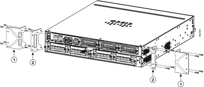
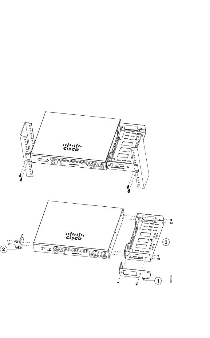
Mount Cisco 4200 ISR Chassis in Rack with AC Power Unit
Step 1![]() Attach the brackets to the router chassis (towards the left or right) as shown in Figure 3-11 and Figure 3-12.
Attach the brackets to the router chassis (towards the left or right) as shown in Figure 3-11 and Figure 3-12.
Figure 3-11 AC Power Bracket Installation for Left Mounting (Cisco 4221 ISR shown)
|
|
|
||
|
|
|
Figure 3-12 AC Power Bracket Installation for Right Mounting (Cisco 4221 ISR shown)
|
|
|
||
|
|
|
After the router is installed, you must connect the chassis to a reliable earth ground. For the chassis ground connection procedures, see the “Chassis Grounding” section.
Chassis Grounding
Warning![]() This equipment must be grounded. Never defeat the ground conductor or operate the equipment in the absence of a suitably installed ground conductor. Contact the appropriate electrical inspection authority or an electrician if you are uncertain that suitable grounding is available. Statement 1024
This equipment must be grounded. Never defeat the ground conductor or operate the equipment in the absence of a suitably installed ground conductor. Contact the appropriate electrical inspection authority or an electrician if you are uncertain that suitable grounding is available. Statement 1024
Warning![]() During this procedure, wear grounding wrist straps to avoid ESD damage to the card. Do not directly touch the backplane with your hand or any metal tool, you could shock yourself. Statement 94
During this procedure, wear grounding wrist straps to avoid ESD damage to the card. Do not directly touch the backplane with your hand or any metal tool, you could shock yourself. Statement 94
You must connect the chassis to a reliable earth ground; the ground wire must be installed in accordance with local electrical safety standards.
- For grounding, use size 6 AWG (13 mm 2) copper wire and the ground lug provided in the accessory kit.
Note![]() This equipment is suitable for installation in Network Telecommunications Facilities and locations where the NEC applies. The equipment is suitable for installation as part of the Common Bonding Network (CBN).
This equipment is suitable for installation in Network Telecommunications Facilities and locations where the NEC applies. The equipment is suitable for installation as part of the Common Bonding Network (CBN).
- For NEC-compliant grounding, use size 14 AWG (2 mm 2) or larger copper wire and an appropriate user-supplied ring terminal with an inner diameter of 1/4 in. (5–7 mm).
- For EN/IEC 60950-1 and EN/IEC 62368-1 compliant grounding, use size 10 AWG (4 mm 2) or larger copper wire and an appropriate user-supplied ring terminal.
To install the ground connection for your router, perform the following steps:
Step 1![]() Strip one end of the ground wire to the length required for the ground lug or terminal.
Strip one end of the ground wire to the length required for the ground lug or terminal.
Step 2![]() Crimp the ground wire to the ground lug or ring terminal using a crimp tool of the appropriate size.
Crimp the ground wire to the ground lug or ring terminal using a crimp tool of the appropriate size.
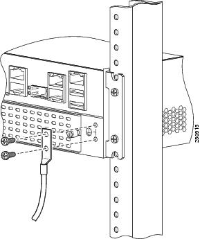
Step 3![]() Attach the ground lug or ring terminal to the chassis as shown in Figure 3-13. For a ground lug, use the two screws with captive locking washers provided. For a ring terminal, use one of the screws provided. Tighten the screws to a torque of 8 to 10 in-lb (0.9 to 1.1 N-m).
Attach the ground lug or ring terminal to the chassis as shown in Figure 3-13. For a ground lug, use the two screws with captive locking washers provided. For a ring terminal, use one of the screws provided. Tighten the screws to a torque of 8 to 10 in-lb (0.9 to 1.1 N-m).
Figure 3-13 Chassis Ground Connection on the Router (Cisco 4451-X ISR shown) Chassis
Step 4![]() Connect the other end of the ground wire to a known reliable earth ground point at your site.
Connect the other end of the ground wire to a known reliable earth ground point at your site.
Connect Power
This section explains how to connect AC power to the router.
Warning![]() Read the installation instructions before connecting the system to the power source. Statement 1004
Read the installation instructions before connecting the system to the power source. Statement 1004
Warning![]() This unit might have more than one power supply connection. All connections must be removed to de-energize the unit. Statement 1028
This unit might have more than one power supply connection. All connections must be removed to de-energize the unit. Statement 1028
Warning![]() Only trained and qualified personnel should be allowed to install, replace, or service this equipment. Statement 1030
Only trained and qualified personnel should be allowed to install, replace, or service this equipment. Statement 1030
Note![]() The installation must comply with all required electrical codes applicable at the installation site.
The installation must comply with all required electrical codes applicable at the installation site.
Warning![]() When installing the product, please use the provided or designated connection cables/power cables/AC adaptors. Using any other cables/adaptors could cause a malfunction or a fire. Electrical Appliance and Material Safety Law prohibits the use of UL-certified cables (that have the “UL” shown on the code) for any other electrical devices than products designated by CISCO. The use of cables that are certified by Electrical Appliance and Material Safety Law (that have “PSE” shown on the code) is not limited to CISCO-designated products. Statement 371.
When installing the product, please use the provided or designated connection cables/power cables/AC adaptors. Using any other cables/adaptors could cause a malfunction or a fire. Electrical Appliance and Material Safety Law prohibits the use of UL-certified cables (that have the “UL” shown on the code) for any other electrical devices than products designated by CISCO. The use of cables that are certified by Electrical Appliance and Material Safety Law (that have “PSE” shown on the code) is not limited to CISCO-designated products. Statement 371.
Connect to AC Power
If your router uses AC power, connect it to a 15 A, 120 VAC (10 A, 240 VAC) circuit with overcurrent protection.
Note![]() The input voltage tolerance limits for AC power are 90 and 264 VAC.
The input voltage tolerance limits for AC power are 90 and 264 VAC.
Note![]() This product requires surge protection to be provided as part of the building installation. To comply with the Telcordia GR-1089 NEBS standard for electromagnetic compatibility and safety, an external surge protective device (SPD) is required at the AC power service equipment.
This product requires surge protection to be provided as part of the building installation. To comply with the Telcordia GR-1089 NEBS standard for electromagnetic compatibility and safety, an external surge protective device (SPD) is required at the AC power service equipment.
Warning![]() AC connected units must have a permanent ground connection in addition to the power cable ground wire. NEBS-compliant grounding satisfies this requirement. Statement 284
AC connected units must have a permanent ground connection in addition to the power cable ground wire. NEBS-compliant grounding satisfies this requirement. Statement 284
Warning![]() This product requires short-circuit (overcurrent) protection, to be provided as part of the building installation. Install only in accordance with national and local wiring regulations. Statement 1045
This product requires short-circuit (overcurrent) protection, to be provided as part of the building installation. Install only in accordance with national and local wiring regulations. Statement 1045
Warning![]() This product relies on the building’s installation for short-circuit (overcurrent) protection. Ensure that the protective device is rated not greater than:
This product relies on the building’s installation for short-circuit (overcurrent) protection. Ensure that the protective device is rated not greater than:
15A, 120VAC (16A, 240VAC). Statement 1005
Connect to Console Terminal or Modem
The router has asynchronous serial ports and auxiliary ports. These ports provide administrative access to the router either locally (with a console terminal or a PC) or remotely (with a modem).To configure the router through the Cisco IOS CLI, you must establish a connection between the router console port and a terminal or a PC.
Use the following cables and adapters to establish a local or remote connection.
|
|
|
|
|---|---|---|
Connect to Serial Port with Microsoft Windows
Note![]() Install the USB device driver before establishing a physical connection between the router and the PC using the USB Console cable plugged into the USB serial port; otherwise, the connection fails. See the “Install Cisco Microsoft Windows USB Device Driver” section.
Install the USB device driver before establishing a physical connection between the router and the PC using the USB Console cable plugged into the USB serial port; otherwise, the connection fails. See the “Install Cisco Microsoft Windows USB Device Driver” section.
Step 1![]() Connect the end of the console cable with the RJ-45 connector to the light blue console port on the router.
Connect the end of the console cable with the RJ-45 connector to the light blue console port on the router.
or
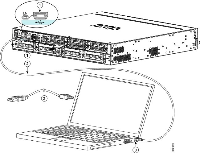
Connect a USB 5-pin mini USB Type-B to the USB console port as shown in Figure 3-14. If you are using the USB serial port for the first time on a Windows-based PC, install the USB driver now according to the instructions in the following sections.
- “Install Cisco Microsoft Windows XP USB Driver” section
- “Install Cisco Microsoft Windows 2000 USB Driver” section
- “Install Cisco Microsoft Windows Vista USB Driver” section
Note![]() You cannot use the USB port and the EIA port concurrently. See “Connect WAN, LAN, and Voice Interfaces” section. When the USB port is used it takes priority over the RJ-45 EIA port.
You cannot use the USB port and the EIA port concurrently. See “Connect WAN, LAN, and Voice Interfaces” section. When the USB port is used it takes priority over the RJ-45 EIA port.
Step 2![]() Connect the end of the cable with the DB-9 connector (or USB Type-A) to the terminal or PC. If your terminal or PC has a console port that does not accommodate a DB-9 connector, you must provide an appropriate adapter for that port.
Connect the end of the cable with the DB-9 connector (or USB Type-A) to the terminal or PC. If your terminal or PC has a console port that does not accommodate a DB-9 connector, you must provide an appropriate adapter for that port.
Step 3![]() To communicate with the router, start a terminal emulator application. This software should be configured with the following parameters:
To communicate with the router, start a terminal emulator application. This software should be configured with the following parameters:
Figure 3-14 Connecting the USB Console Cable to the Router (shown: Cisco ISR 4451-X)
Connect to Console Port with Mac OS X
You connect a Mac OS X system USB port to the console using the built-in OS X Terminal utility.
Step 1![]() Use the Finder to go to Applications > Utilities > Terminal.
Use the Finder to go to Applications > Utilities > Terminal.
Step 2![]() Connect the OS X USB port to the router.
Connect the OS X USB port to the router.
Step 3![]() Enter the following commands to find the OS X USB port number:
Enter the following commands to find the OS X USB port number:
DT-macbook:dev user$
Step 4![]() Connect to the USB port with the following command followed by the router USB port speed:
Connect to the USB port with the following command followed by the router USB port speed:
To disconnect the OS X USB console from the Terminal window
Enter Ctrl-a followed by Ctrl-\
Connect to Console Port with Linux
You connect a Linux system USB port to the console using the built-in Linux Terminal utility.
Step 1![]() Open the Linux Terminal window.
Open the Linux Terminal window.
Step 2![]() Connect the Linux USB port to the router.
Connect the Linux USB port to the router.
Step 3![]() Enter the following commands to find the Linux USB port number:
Enter the following commands to find the Linux USB port number:
Step 4![]() Connect to the USB port with the following command followed by the router USB port speed:
Connect to the USB port with the following command followed by the router USB port speed:
To disconnect the Linux USB console from the Terminal window
Enter Ctrl-a followed by : then quit
Install Cisco Microsoft Windows USB Device Driver
A USB device driver must be installed the first time a Microsoft Windows-based PC is connected to the USB serial port on the router.
This section contains the following topics:
- “Install Cisco Microsoft Windows XP USB Driver”
- “Install Cisco Microsoft Windows 2000 USB Driver”
- “Install Cisco Microsoft Windows Vista USB Driver”
Install Cisco Microsoft Windows XP USB Driver
Before you begin, download the appropriate driver for your router model from the Cisco Software Download site, USB Console Software category: http://www.cisco.com/cisco/software/navigator.html?mode=prod
Step 1![]() Unzip the file Cisco_usbconsole_driver_X_X.zip (where X is the revision number).
Unzip the file Cisco_usbconsole_driver_X_X.zip (where X is the revision number).
Step 2![]() If you are using 32-bit Windows XP, double-click the file setup.exe from the Windows_32 folder; if you are using 64-bit Windows XP, double-click the file setup(x64).exe from the Windows_64 folder.
If you are using 32-bit Windows XP, double-click the file setup.exe from the Windows_32 folder; if you are using 64-bit Windows XP, double-click the file setup(x64).exe from the Windows_64 folder.
The Cisco Virtual Com InstallShield Wizard begins.
Step 3![]() Click Next. The Ready to Install the Program window appears,
Click Next. The Ready to Install the Program window appears,
Step 4![]() Click Install. The InstallShield Wizard Completed window appears.
Click Install. The InstallShield Wizard Completed window appears.
Step 6![]() Connect the USB cable to the PC and router USB console ports. See Table 3-1 . The EN LED for the USB console port turns green, and the Found New Hardware Wizard displays. Follow the instructions in the wizard to complete the installation of the driver.
Connect the USB cable to the PC and router USB console ports. See Table 3-1 . The EN LED for the USB console port turns green, and the Found New Hardware Wizard displays. Follow the instructions in the wizard to complete the installation of the driver.
The USB console is ready for use.
Install Cisco Microsoft Windows 2000 USB Driver
Step 1![]() Obtain the file Cisco_usbconsole_driver.zip from cisco.com and unzip it.
Obtain the file Cisco_usbconsole_driver.zip from cisco.com and unzip it.
Step 2![]() Double-click the file setup.exe. The Cisco Virtual Com InstallShield Wizard begins.
Double-click the file setup.exe. The Cisco Virtual Com InstallShield Wizard begins.
Step 3![]() Click Next. The Ready to Install the Program window appears.
Click Next. The Ready to Install the Program window appears.
Step 4![]() Click Install. The InstallShield Wizard Completed window appears.
Click Install. The InstallShield Wizard Completed window appears.
Step 6![]() Connect the USB cable to the PC and router USB console ports. See Table 3-1 . The EN LED for the USB console port turns green, and the Found New Hardware Wizard window displays. Follow the instructions in the wizard to complete the installation of the driver.
Connect the USB cable to the PC and router USB console ports. See Table 3-1 . The EN LED for the USB console port turns green, and the Found New Hardware Wizard window displays. Follow the instructions in the wizard to complete the installation of the driver.
The USB console is ready for use.
Install Cisco Microsoft Windows Vista USB Driver
Step 1![]() Obtain the file Cisco_usbconsole_driver.zip from cisco.com and unzip it.
Obtain the file Cisco_usbconsole_driver.zip from cisco.com and unzip it.
Step 2![]() If you are using 32-bit Windows Vista, double-click the file setup.exe from the Windows_32 folder; if your are using 64-bit Windows Vista, double-click the file setup(x64).exe from the Windows_64 folder. The Cisco Virtual Com InstallShield Wizard begins.
If you are using 32-bit Windows Vista, double-click the file setup.exe from the Windows_32 folder; if your are using 64-bit Windows Vista, double-click the file setup(x64).exe from the Windows_64 folder. The Cisco Virtual Com InstallShield Wizard begins.
Step 3![]() Click Next. The Ready to Install the Program window appears,
Click Next. The Ready to Install the Program window appears,
Step 4![]() Click Install. The InstallShield Wizard Completed window appears.
Click Install. The InstallShield Wizard Completed window appears.
Note![]() If a User Account Control warning appears, click “Allow - I trust this program...” to proceed.
If a User Account Control warning appears, click “Allow - I trust this program...” to proceed.
Step 6![]() Connect the USB cable to the PC and router USB console ports. See Table 3-1 . The EN LED for the USB console port turns green, and a pop up window stating “Installing device driver software” appears. Follow subsequent instructions in the wizard to complete the installation of the driver.
Connect the USB cable to the PC and router USB console ports. See Table 3-1 . The EN LED for the USB console port turns green, and a pop up window stating “Installing device driver software” appears. Follow subsequent instructions in the wizard to complete the installation of the driver.
The USB console is ready for use.
Install the Silicon Labs USB Device Driver
This section contains the following topics:
Install the Silicon Labs Windows USB Driver
Step 1![]() Go to the Silicon Labs website ( www.silabs.com/developers/usb-to-uart-bridge-vcp-drivers?tab=downloads), and click CP210x Universal Windows Driver.
Go to the Silicon Labs website ( www.silabs.com/developers/usb-to-uart-bridge-vcp-drivers?tab=downloads), and click CP210x Universal Windows Driver.
Step 2![]() Unzip the downloaded folder, and select the installer for your system configuration. The Device Driver Installation Wizard begins.
Unzip the downloaded folder, and select the installer for your system configuration. The Device Driver Installation Wizard begins.
Step 3![]() Click Next on the Installation Wizard, then click Finish to complete installation.
Click Next on the Installation Wizard, then click Finish to complete installation.
Step 4![]() Open the Device Manager on your system and click the Ports (COM & LPT) drop-down.
Open the Device Manager on your system and click the Ports (COM & LPT) drop-down.
Step 5![]() Insert the USB console cable and power into your system. The Device manager refreshes and indicates the newly-detected COM port.
Insert the USB console cable and power into your system. The Device manager refreshes and indicates the newly-detected COM port.
Step 6![]() Open a terminal emulator and click the Serial connection type. Input the values for Serial Line and Speed (or Baud Rate).
Open a terminal emulator and click the Serial connection type. Input the values for Serial Line and Speed (or Baud Rate).
Step 8![]() The terminal emulator opens. Click Enter to view the console output response.
The terminal emulator opens. Click Enter to view the console output response.
Install the Silicon Labs Mac USB Driver
Step 1![]() Go to the Silicon Labs website ( www.silabs.com/developers/usb-to-uart-bridge-vcp-drivers?tab=downloads), and click CP210x VCP Mac OS Driver.
Go to the Silicon Labs website ( www.silabs.com/developers/usb-to-uart-bridge-vcp-drivers?tab=downloads), and click CP210x VCP Mac OS Driver.
Step 2![]() Click the Downloads folder, then click the macOS_VCP_Driver folder, and double-click the SiLabsUSBDriverDisk.dmg program.
Click the Downloads folder, then click the macOS_VCP_Driver folder, and double-click the SiLabsUSBDriverDisk.dmg program.
Step 3![]() Click Install CP210X VCP Driver, and then click Open. The Driver Installer begins.
Click Install CP210X VCP Driver, and then click Open. The Driver Installer begins.
Step 4![]() Follow installer instructions. Click Continue, scroll all the way down, then click Continue, and click Agree.
Follow installer instructions. Click Continue, scroll all the way down, then click Continue, and click Agree.
Step 5![]() Click Continue, and enter your password. Then click Install Helper, and click Close.
Click Continue, and enter your password. Then click Install Helper, and click Close.
Step 6![]() Insert the USB console cable and power into your system.
Insert the USB console cable and power into your system.
Step 7![]() Open a terminal and type cd/dev, and then type ls-ltr. Serial port tty.SLAB_USBtoUART appears.
Open a terminal and type cd/dev, and then type ls-ltr. Serial port tty.SLAB_USBtoUART appears.
Step 8![]() Type screen/dev/tty.SLAB_USBtoUART <baudrate> to see console output. Console will show response upon first Enter key if there is no output.
Type screen/dev/tty.SLAB_USBtoUART <baudrate> to see console output. Console will show response upon first Enter key if there is no output.
The USB console is ready for use.
Uninstall Cisco Microsoft Windows USB Driver
To uninstall the Cisco Microsoft Windows USB device driver.
- “Uninstall Cisco Microsoft Windows XP and 2000 USB Driver”
- “Uninstall Cisco Microsoft Windows Vista USB Driver”
Uninstall Cisco Microsoft Windows XP and 2000 USB Driver
This procedure shows you how to uninstall both the Microsoft Windows XP and 2000 USB driver. The driver can be removed using the Windows Add Remove Programs utility or the setup.exe program.
Using the Add Remove Programs utility
Note![]() Disconnect the router console terminal before uninstalling the driver.
Disconnect the router console terminal before uninstalling the driver.
Step 1![]() Click Start > Control Panel > Add or Remove Programs.
Click Start > Control Panel > Add or Remove Programs.
Step 2![]() Scroll to Cisco Virtual Com and click Remove.
Scroll to Cisco Virtual Com and click Remove.
The Program Maintenance window appears,
Step 3![]() Select the Remove radio button. Click Next.
Select the Remove radio button. Click Next.
Note![]() Disconnect the router console terminal before uninstalling the driver.
Disconnect the router console terminal before uninstalling the driver.
Step 1![]() Run the setup.exe for Windows 32-bit or setup(x64).exe for Windows-64bit. Click Next. The InstallShield Wizard for Cisco Virtual Com appears.
Run the setup.exe for Windows 32-bit or setup(x64).exe for Windows-64bit. Click Next. The InstallShield Wizard for Cisco Virtual Com appears.
Step 2![]() Click Next. The Program Maintenance window appears.
Click Next. The Program Maintenance window appears.
Step 3![]() Select the Remove radio button and click Next. The Remove the Program window appears,
Select the Remove radio button and click Next. The Remove the Program window appears,
Step 4![]() Click Remove. The InstallShield Wizard Completed window appears.
Click Remove. The InstallShield Wizard Completed window appears.
Uninstall Cisco Microsoft Windows Vista USB Driver
Note![]() Disconnect the router console terminal before uninstalling the driver.
Disconnect the router console terminal before uninstalling the driver.
Step 1![]() Run the setup.exe for Windows 32-bit or setup(x64).exe for Windows-64bit. Click Next.
Run the setup.exe for Windows 32-bit or setup(x64).exe for Windows-64bit. Click Next.
The InstallShield Wizard for Cisco Virtual Com appears.
Step 2![]() Click Next The Program Maintenance window appears.
Click Next The Program Maintenance window appears.
Step 3![]() Select the Remove radio button and click Next. The Remove the Program window appears.
Select the Remove radio button and click Next. The Remove the Program window appears.
Step 4![]() Click Remove. The InstallShield Wizard Completed window appears.
Click Remove. The InstallShield Wizard Completed window appears.
Note![]() If a User Account Control warning appears, click “Allow - I trust this program...” to proceed.
If a User Account Control warning appears, click “Allow - I trust this program...” to proceed.
Connect WAN, LAN, and Voice Interfaces
Warning![]() Do not work on the system or connect or disconnect cables during periods of lightning activity. Statement 1001
Do not work on the system or connect or disconnect cables during periods of lightning activity. Statement 1001
Warning![]() To avoid electric shock, do not connect safety extra-low voltage (SELV) circuits to telephone-network voltage (TNV) circuits. LAN ports contain SELV circuits, and WAN ports contain TNV circuits. Some LAN and WAN ports both use RJ-45 connectors. Use caution when connecting cables. Statement 1021
To avoid electric shock, do not connect safety extra-low voltage (SELV) circuits to telephone-network voltage (TNV) circuits. LAN ports contain SELV circuits, and WAN ports contain TNV circuits. Some LAN and WAN ports both use RJ-45 connectors. Use caution when connecting cables. Statement 1021
Warning![]() Hazardous network voltages are present in WAN ports regardless of whether power to the unit is OFF or ON. To avoid electric shock, use caution when working near WAN ports. When detaching cables, detach the end away from the unit first. Statement 1026
Hazardous network voltages are present in WAN ports regardless of whether power to the unit is OFF or ON. To avoid electric shock, use caution when working near WAN ports. When detaching cables, detach the end away from the unit first. Statement 1026
Warning![]() Never install telephone jacks in wet locations unless the jack is specifically designed for wet locations. Statement 1036
Never install telephone jacks in wet locations unless the jack is specifically designed for wet locations. Statement 1036
Warning![]() Never touch uninsulated telephone wires or terminals unless the telephone line has been disconnected at the network interface. Statement 1037
Never touch uninsulated telephone wires or terminals unless the telephone line has been disconnected at the network interface. Statement 1037
Ports and Cabling
Table 3-2 summarizes typical WAN, LAN, and voice connections for routers. The connections summarized here are also described in detail in Cisco Modular Access Router Cable Specifications.
|
|
|
|
|
|---|---|---|---|
RJ-48 T1/E1 |
|||
| Cisco serial transition cable that matches the signaling protocol (EIA/TIA-232, EIA/TIA-449, V.35, X.21, or EIA-530) |
|||
|
|
Connection Procedures and Precautions
- Connect each WAN, LAN, and voice cable to the appropriate connector on the chassis or on a network module or interface card.
- Position the cables carefully, so that they do not put strain on the connectors.
- Organize cables in bundles so that cables do not intertwine.
- Inspect the cables to make sure that the routing and bend radius is satisfactory. Reposition cables, if necessary.
- Install cable ties in accordance with site requirements.
For cable pinouts, see Cisco Modular Access Router Cable Specifications.
 Feedback