Cisco 1811 and 1812 Integrated Services Router Cabling and Installation
Available Languages
Table Of Contents
Cisco 1811 and 1812 Integrated Services Router Cabling and Installation
Cisco One-Year Limited Hardware Warranty Terms
Product Serial Number Location
Connecting Antennas to the Router RP-TNC Connectors
Configuring the Router Using Cisco Router and Security Device Manager
Connecting a PC to the Router Console Port
Obtaining Documentation and Submitting a Service Request
Quick Start Guide
Cisco 1811 and 1812 Integrated Services Router Cabling and Installation
INCLUDES LICENSE AND WARRANTY INFORMATIONNote: For localized versions of these instructions, please see the following URL:
http://www.cisco.com/en/US/partner/products/ps5853/prod_installation_guides_list.html
1 Cisco One-Year Limited Hardware Warranty Terms
There are special terms applicable to your hardware warranty and various services that you can use during the warranty period. Your formal Warranty Statement, including the warranty applicable to Cisco software, is included on the CD that accompanies your Cisco product. Follow these steps to access and download the Cisco Information Packet and your warranty document from the CD or from Cisco.com.
1.
Launch your browser, and go to this URL:
http://www.cisco.com/univercd/cc/td/doc/es_inpck/cetrans.htm
The Warranties and License Agreements page appears.
2.
a.
b.
You must have Adobe Acrobat Reader to view and print PDF files. You can download the reader from Adobe's website:
You can also contact the Cisco service and support website for assistance:
http://www.cisco.com/en/US/support/.
Duration of Hardware Warranty
One (1) Year
Replacement, Repair, or Refund Policy for Hardware
Cisco or its service center will use commercially reasonable efforts to ship a replacement part within ten (10) working days after receipt of a Return Materials Authorization (RMA) request. Actual delivery times can vary, depending on the customer location.
Cisco reserves the right to refund the purchase price as its exclusive warranty remedy.
To Receive a Return Materials Authorization (RMA) Number
Contact the company from whom you purchased the product. If you purchased the product directly from Cisco, contact your Cisco Sales and Service Representative.
Complete the information below, and keep it for reference.
Company product purchased from
Company telephone number
Product model number
Product serial number
Maintenance contract number
2 Overview
This document describes the steps for installing the Cisco 1811 and the Cisco 1812 integrated services routers. The Cisco 1811 and Cisco 1812 routers are fixed-configuration routers. They each include an integrated 8-port 10/100-Mbps Ethernet switch, two onboard Fast Ethernet WAN ports, two dual USB 2.0 ports, and optional 802.11a/b/g wireless LAN support. The switch ports and the onboard 10/100-Mbps Ethernet ports support 802.1Q virtual LAN (VLAN) encapsulation and enable you to configure demilitarized zones (DMZs), using VLANs and Cisco IOS firewall features. The switch ports are also optionally upgradable to include inline power support for IP phones.
The Cisco 1811 and Cisco 1812 integrated services routers provide secure Internet connectivity and dial backup if your primary connection fails. The Cisco 1811 router provides dial backup through a V.92 analog modem port. The Cisco 1812 router provides dial backup through an ISDN S/T port.
Additional documentation can be found on Cisco.com.
Product Serial Number Location
The serial number label for the Cisco 1811 and Cisco 1812 routers is located on the back of the chassis, above and to the right of the power switch. You need this serial number when calling Cisco for support. To see specifically where the serial label is on your router, go to the following link:
http://tools.cisco.com/Support/CPI/index.do
3 Unpacking the Box
When you unpack the box containing your Cisco 1811 or Cisco 1812 router, you should find the items shown in Figure 1.

Note
Figure 1 Items Included with the Cisco 1811 and Cisco 1812 Integrated Services Router
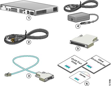
Cisco 1811 or Cisco 1812 router
PoE power supply and cable (optional)
Power cable
DB-9 to DB-25 adapter
Console cable (light blue, RJ-45 to DB-9)
Product documentation
The shipment should include the following items:
•
•
•
•
•
•
•
•
Items You Need to Provide
Depending on your network environment, you may need to provide some of the following items so that you can install the router:
•
•
•
4 Connecting the Router
Figure 2 shows a typical installation of a Cisco 1811 or Cisco 1812 router.
Figure 2 Typical Installation of a Cisco 1811 or Cisco 1812 Router
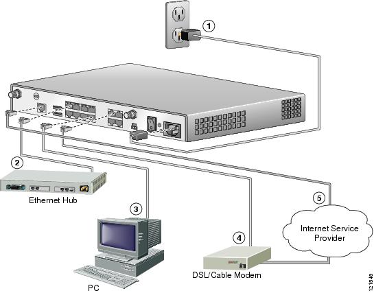
Follow these steps to connect the router to the power supply, your local network, and your service provider network:
Step 1
a.
b.
Note
c.
d.
Step 2
Note
Step 3

Caution
Step 4
Caution
Step 5
Note
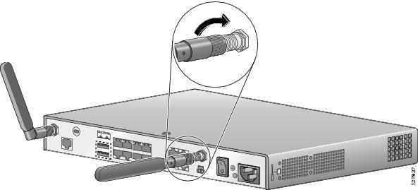
5 Connecting Antennas to the Router RP-TNC Connectors
If your router has the wireless LAN option, connect the antennas by screwing the antenna connectors in a clockwise direction onto the reverse-polarity threaded Neill-Concelman (RP-TNC) connectors on the back panel of the router. Figure 3 shows an example of how to connect the swivel-mount dipole antennas to the router.
Note
http://www.cisco.com/en/US/products/ps5853/prod_installation_guides_list.html
Figure 3 Connecting Antennas to the Router
For information about configuring the wireless LAN functionality of your router, see the Cisco Access Router Wireless Configuration Guide at the following URL:
http://www.cisco.com/en/US/docs/routers/access/1800/wireless/configuration/guide/awg.html
6 Configuring the Router Using Cisco Router and Security Device Manager
Cisco Router and Security Device Manager (SDM) is a web-based configuration tool that allows you to configure LAN and WAN interfaces, routing, Network Address Translation (NAT), firewalls, VPNs, and other features on your router. If SDM is installed on your router, configure the router by following the instructions in the Cisco Router and Security Device Manager (SDM) Quick Start Guide. If this document was not shipped with your router, you can obtain the SDM software and instructions for installing it on your router from the following location:
http://www.cisco.com/pcgi-bin/tablebuild.pl/sdm
To obtain the SDM release notes and other SDM documentation, go to the following URL and click the Technical Documentation link.
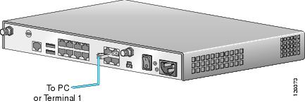
7 Connecting a PC to the Router Console Port
This step is optional; it is required only if you want to use the Cisco IOS CLI instead of SDM to configure or troubleshoot the router. To use Cisco IOS, you must connect the router to a terminal or to a PC with terminal emulation software. Terminal emulation software should be configured with the following settings:
•
•
•
•
The Cisco 1800 Series Integrated Services Routers (Fixed) Software Configuration Guide describes how to configure the router by using Cisco IOS software.
Follow these steps to connect the router to a terminal or PC:
Step 1
Figure 4 Connecting the Console Cable to the Router
Step 2
8 Verifying Your Installation
You can verify that you have correctly installed your router by checking the LEDs as described in Table 1.
Table 1 LEDs That Verify Installation
SYS OK
Steady green—Router has successfully booted up and the software is functional.
Blinking green—Router is booting or in ROM monitor mode.
POE1
Off—Inline power supply not installed.
Steady green—Inline power supply OK.
Amber—Power denied.
FE 0-9
Steady green—Ethernet link is established.
Blinking green—Activity on the Ethernet link.
Off—No link.
CD2
Steady green—Modem connection established (carrier detect).
Off—No connection established.
SPD2
Steady green—Connection at high speed (V.90).
Off—Connection at low speed (V.32/V.32b/V.34).
BUSY2
Blinking green—Activity over modem line.
Off—No activity.
LINK3
Steady green—ISDN S/T connection established.
Off—No ISDN S/T connection established.
B13
Blinking green—Activity on first B channel.
Off—No activity on first B channel.
B23
Blinking green—Activity on second B channel.
Off—No activity on second B channel.
PPP
Steady green—At least one PPP connection established.
Off—No PPP link established.
VPN
Steady green—At least one VPN tunnel established.
Off—No VPN tunnel established.
CF
Blinking green—CompactFlash memory being accessed. Do not remove CompactFlash memory.
Off—CompactFlash memory is not being accessed. It is safe to remove CompactFlash memory.
1 Inline power is a field-upgradable option only. It is not installed by default.
2 This LED is on the Cisco 1811 router only.
3 This LED is on the Cisco 1812 router only.
9 Obtaining Documentation and Submitting a Service Request
For information on obtaining documentation, submitting a service request, and gathering additional information, see the monthly What's New in Cisco Product Documentation, which also lists all new and revised Cisco technical documentation, at:
http://www.cisco.com/en/US/docs/general/whatsnew/whatsnew.html
Subscribe to the What's New in Cisco Product Documentation as a Really Simple Syndication (RSS) feed and set content to be delivered directly to your desktop using a reader application. The RSS feeds are a free service and Cisco currently supports RSS version 2.0.
 Feedback
Contact Cisco
- Open a Support Case

- (Requires a Cisco Service Contract)