Cisco 7301 Installation and Configuration Guide
Bias-Free Language
The documentation set for this product strives to use bias-free language. For the purposes of this documentation set, bias-free is defined as language that does not imply discrimination based on age, disability, gender, racial identity, ethnic identity, sexual orientation, socioeconomic status, and intersectionality. Exceptions may be present in the documentation due to language that is hardcoded in the user interfaces of the product software, language used based on RFP documentation, or language that is used by a referenced third-party product. Learn more about how Cisco is using Inclusive Language.
- Updated:
- September 20, 2005
Chapter: Specifications
Specifications
This appendix provides router specifications and cable assemblies and pinouts for the cables shipped with the Cisco 7301 router.
For additional information on how the cables are physically connected to the devices, see, Chapter 1, "Cisco 7301 Overview," and Chapter 2, "Rack-Mounting, Tabletop Installation, and Cabling."
This appendix includes the following cable assembly and pinout information:
•![]() Cisco 7301 Router Specifications
Cisco 7301 Router Specifications
•![]() Processor and Memory Specifications
Processor and Memory Specifications
•![]() SFP GBIC Module Configurations
SFP GBIC Module Configurations
•![]() Gigabit Ethernet RJ-45 Port Pinouts
Gigabit Ethernet RJ-45 Port Pinouts
•![]() Console Port and Auxiliary Port Signals and Pinouts
Console Port and Auxiliary Port Signals and Pinouts
Cisco 7301 Router Specifications
The specifications for the Cisco 7301 router are listed in Table A-1.
|
|
|
|---|---|
Dimensions (H x W x D) |
1.73 in. x 17.3 in. x 13.87 in. (4.39 cm x 43.9 cm x 35.23 cm) |
Weight |
Chassis fully configured with a port adapter ~ 10.5 lb (4.76 kg) |
Heat dissipation |
50W (170 BTU) typical, 75W (255 BTU1 ) maximum |
Power dissipation |
75W maximum configuration |
Single and Dual AC Power Supply Information |
|
AC-input power |
75W maximum (single supply configuration) |
AC-input voltage rating |
100-240 VAC2 wide input with power factor correction |
AC-input current rating |
Rated for 2A Not to exceed 1.0A3 maximum at 100 VAC and .05A maximum at 240 VAC |
AC-input frequency rating |
50-60 Hz4 |
AC-input cable |
18 AWG5 three-wire cable, with a three-lead IEC-320 receptacle on the power supply end, and a country-dependent plug on the power source end |
|
|
|
DC-input power |
75W maximum configuration |
DC-input voltage ratings |
+24 VDC6 nominal. Maximum range +18 to +36 VDC |
DC-input current ratings |
Rated for 6A. Not to exceed 3A at +24 VDC (50A at 34 VDC = 2.1A typical draw) |
DC-input cable |
18 AWG recommended minimum, with at least 2 conductors rated for at least 140oF (60oC) |
|
|
|
DC-input voltage rating |
-48 VDC nominal in North America, -60 VDC nominal in some areas of the European Community. Maximum range is -40.5 to 72 VDC. |
DC-input current rating |
Rated for 3A. Not to exceed 1.6A at -48 VDC (50A at 48 VDC = 1.1A typical draw) |
DC-input cable |
18 AWG stranded recommended minimum, rated for at least 140oF (60oC) |
Temperature |
32 to 104oF (0 to 40oC) operating; -4 to 149oF (-20 to 65oC) nonoperating |
Humidity |
10 to 90% noncondensing |
1 BTU = British thermal units 2 VAC = volts alternating current 3 A = amperes 4 Hz = hertz 5 AWG = American Wire Gauge 6 VDC = volts direct current |

Note ![]() If required, use Sinewave Output UPS (uninterruptable power supply), not Ferro-resonant type UPS.
If required, use Sinewave Output UPS (uninterruptable power supply), not Ferro-resonant type UPS.
Software Requirements
The minimum software requirement for the Cisco 7301 router is Cisco IOS Release 12.2(11)YZ and Release 12.2(13)B.
To check the minimum software requirements of Cisco IOS software with the hardware installed on your router, Cisco maintains the Software Advisor tool on Cisco.com. This tool does not verify whether modules within a system are compatible, but it does provide the minimum IOS requirements for individual hardware modules or components.
Note ![]() Access to this tool is limited to users with Cisco.com login accounts.
Access to this tool is limited to users with Cisco.com login accounts.
To access Software Advisor, click Log In at Cisco.com and go to Technical Support. You can also access the tool by pointing your browser directly to http://www.cisco.com/en/US/customer/products/sw/secursw/ps2136/products_software_advisor_tool_
launch.html.
Choose a product family or enter a specific product number to search for the minimum supported software release needed for your hardware.
Processor and Memory Specifications
|
|
|
|
|
|---|---|---|---|
1 |
64 MB |
Contains the default Cisco IOS image |
MEM-7301-FLD64M= |
1 |
128 MB |
MEM-7301-FLD128M= |
|
|
|
|
|---|---|---|
256 MB |
2 128-MB SODIMMs |
MEM-7301-256MB= |
512 MB |
2 256-MB SODIMMs |
MEM-7301-512-MB= |
1 GB |
2 512-MB SODIMMs |
MEM-7301-1GB= |
SFP GBIC Module Configurations
See Table A-6 for a list of the CWDN SFPs supported on the Cisco 7301 router.
For specification and cabling information, see the following documentation:
•![]() Cisco Small Form-Factor Pluggable Gigabit Interface Converter Data Sheet.
Cisco Small Form-Factor Pluggable Gigabit Interface Converter Data Sheet.
•![]() Cisco 1000BASE-T SFP Data Sheet.
Cisco 1000BASE-T SFP Data Sheet.
•![]() Cisco CWDM GBIC/SFP Solution Data Sheet.
Cisco CWDM GBIC/SFP Solution Data Sheet.
•![]() Cisco Coarse Wavelength-Divsion Multiplexing SFP Compatability Matrix.
Cisco Coarse Wavelength-Divsion Multiplexing SFP Compatability Matrix.
Gigabit Ethernet RJ-45 Port Pinouts
The Cisco 7301 router has RJ-45 ports for the three 10/100/1000 Gigabit Ethernet/Fast Ethernet/Ethernet connections. The RJ-45 ports support IEEE 802.3ab (Gigabit Ethernet) and IEEE 802.3u (Fast Ethernet) interfaces compliant with 10BASET, 100BASETX, and 1000BASET specifications.
The RJ-45 ports support standard straight-through and crossover Category 5 UTP cables with RJ-45 connectors. Cisco Systems does not supply Category 5 UTP cables; these cables are available commercially.

Warning ![]() To avoid electric shock, do not connect safety extra-low voltage (SELV) circuits to telephone-network voltage (TNV) circuits. LAN ports contain SELV circuits, and WAN ports contain TNV circuits. Some LAN and WAN ports both use RJ-45 connectors. Use caution when connecting cables. Statement 76
To avoid electric shock, do not connect safety extra-low voltage (SELV) circuits to telephone-network voltage (TNV) circuits. LAN ports contain SELV circuits, and WAN ports contain TNV circuits. Some LAN and WAN ports both use RJ-45 connectors. Use caution when connecting cables. Statement 76
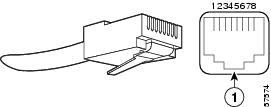
Figure A-1 shows an RJ-45 port and connector. Table A-7Table A-7 lists the pinouts and signals for the RJ-45 port.
Figure A-1 RJ-45 Port and Connector
|
|
RJ-45 connector |
|
|
|
|
|---|---|---|
1 |
TX DATA+1 |
Tx A+ |
2 |
TX DATA- |
Tx A- |
3 |
RX DATA+2 |
Rx B+ |
4 |
N/C |
Tx C+ |
5 |
N/C |
Tx C- |
6 |
RX DATA- |
Rx B- |
7 |
N/C |
Rx D+ |
8 |
N/C |
Rx D- |
1 TX DATA = Transmit Data 2 RX DATA = Receive Data |
Note ![]() With reference to the RJ-45 pinouts in Table A-7Table A-7, proper common-mode line terminations should be used for the unused Category 5 UTP cable pairs 4/5 and 7/8. Common-mode termination reduces electromagnetic interference (EMI).
With reference to the RJ-45 pinouts in Table A-7Table A-7, proper common-mode line terminations should be used for the unused Category 5 UTP cable pairs 4/5 and 7/8. Common-mode termination reduces electromagnetic interference (EMI).
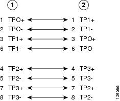
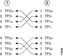
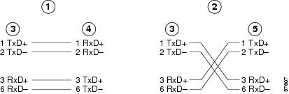
Depending on your RJ-45 interface cabling requirements, use the pinouts shown in Figure A-2 and Figure A-3 for Gigabit Ethernet straight-through and crossover twisted-pair cable connections. Use Figure A-4 for Ethernet/Fast Ethernet straight-through and crossover twisted-pair cable connections.
Figure A-2 Four Twisted-Pair Straight-Through Cable Schematics for 10/100/1000 and 1000BASE-T GBIC Module Ports
|
|
Router |
|
Hub |
Figure A-3 Four Twisted-Pair Crossover Cable Schematics for 10/100/1000 and 1000BASE-T GBIC Module Ports
|
|
Router |
|
Hub |
Figure A-4 Ethernet, Fast Ethernet Pinouts—Straight-Through or Crossover Cable
|
|
Straight-through cable pinout, Ethernet port to a hub or repeater |
|
Hub |
|
|
Crossover cable pinout, Ethernet port to a DTE |
|
DTE |
|
|
Ethernet port |
To determine whether a UTP cable is a crossover cable or a straight-through cable, hold the two RJ-45 connectors next to each other so you can see the colored wires inside the ends, as shown in Figure A-5.
Figure A-5 Identifying a Crossover or Straight-Through Cable
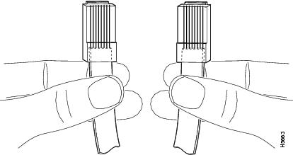
Examine the sequence of colored wires to determine the type of cable, as follows:
•![]() Straight-through—The colored wires are in the same sequence at both ends of the cable.
Straight-through—The colored wires are in the same sequence at both ends of the cable.
•![]() Crossover—The first (far left) colored wire at one end of the cable is the third colored wire at the other end of the cable.
Crossover—The first (far left) colored wire at one end of the cable is the third colored wire at the other end of the cable.
You can identify a rollover cable by comparing the two modular ends of the cable. Holding the cables in your hand, side-by-side, with the tab at the back, the wire connected to the pin on the outside of the left connector (pin 1) should be the same color as the pin on the outside of the right connector (pin 8).
Table A-8 provides information about asynchronous device cabling options.
|
|
|
|
|---|---|---|
Crossover |
RJ-45-to-DB-25M |
Terminal or DTE |
Crossover |
RJ-45-to-DB-9M |
Terminal or DTE |
Straight-through |
RJ-45-to-DB-25F |
Modem or DCE |
Console Port and Auxiliary Port Signals and Pinouts
Note ![]() The console cable kit product number is ACS-2500ASYN.
The console cable kit product number is ACS-2500ASYN.
The Cisco 7301 router does not support Data Carrier Detect (DCD).
Table A-10 lists the RJ-45 auxiliary port signals.
|
|
|
|
|
|---|---|---|---|
|
|
RTS |
Out |
Ready to Send |
|
|
DTR |
Out |
Data Terminal Ready |
|
|
TXD |
Out |
Transmit Data |
|
|
RING1 |
In |
Ring Indication |
|
|
GND |
— |
Signal Ground |
|
|
RXD |
In |
Receive Data |
|
|
DSR/DCD (RLSD) |
In |
Data Set Ready/Data Carrier Detect (Receive Line Signal Detect) |
|
|
CTS |
In |
Clear to Send (tracks RTS) |
1 RING is not supported on Cisco-supplied adapters. To use this pin, you must create a customized cable. 2 Pin 7 can be used as a DCD input for connection to a modem. The RJ-45-to-DB-25F adapter maps DCD to this pin when used with a straight-through cable. |
Alarm Port
The dry relay alarm port operates up to 50V AC/DC maximum and up to 80 mA maximum. Total power dissipation should not exceed 300 milliwatts. The normally closed position will have from 15 to 30 ohms resistance. The open position will be greater than 1 megohm. The alarm condition is the closed position. This port is a switch so that the cable connector can be inserted in either orientation.
Lithium Battery Caution

Caution
Replace only with the same or equivalent type recommended by the manufacturer. Dispose of used batteries according to the manufacturers instructions.
 Feedback