Table Of Contents
Port Adapter Jacket Card Installation Guide
Interface Address Format of the Port Adapter Jacket Card
Electrical Equipment Guidelines
Electrostatic Discharge Prevention
Order of Software and Hardware Installation
Powering Down the Router and Disconnecting Input Power
Removing the I/O Controller Blank Panel or I/O Controller
Removing an I/O Controller Blank Panel
Installing a Port Adapter Jacket Card and Port Adapter
Removing a Port Adapter and Port Adapter Jacket Card
Reconnecting Input Power and Powering Up the Router
Obtaining Documentation, Obtaining Support, and Security Guidelines
Port Adapter Jacket Card Installation Guide
This document provides installation information about Cisco 7200 VXR router Port Adapter Jacket Card, Product ID C7200-JC-PA.
Document Revision History
The Document Revision History table below records technical changes to this document.
Contents
This document contains the following sections:
•Interface Address Format of the Port Adapter Jacket Card
•Hardware and Software Support
•Order of Software and Hardware Installation
•Powering Down the Router and Disconnecting Input Power
•Removing the I/O Controller Blank Panel or I/O Controller
•Installing a Port Adapter Jacket Card and Port Adapter
•Removing a Port Adapter and Port Adapter Jacket Card
•Reconnecting Input Power and Powering Up the Router
•Obtaining Documentation, Obtaining Support, and Security Guidelines
Product Overview
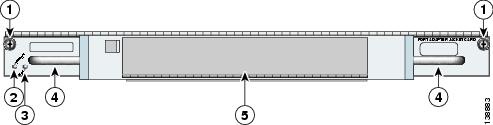
The Port Adapter Jacket Card is used in the I/O controller slot of a Cisco 7200 VXR router with an NPE-G1 or NPE-G2 installed, and allows a port adapter to be installed in it. Both the NPE-G1 or NPE-G2 incorporate I/O controller functionality, so that the I/O controller slot is available for the Port Adapter Jacket Card. The NPE-G1 or NPE-G2 has a third dedicated peripheral component interconnect (PCI) bus that provides additional bandwidth to the chassis. The third PCI bus allows a port adapter with a high bandwidth point requirement to be used with the Port Adapter Jacket Card in the I/O controller slot.
Figure 1 Port Adapter Jacket Card Faceplate
Interface Address Format of the Port Adapter Jacket Card
With the Port Adapter Jacket Card installed in a Cisco 7200 VXR router, the Port Adapter Jacket Card slot address is identified as slot 0. While the Port Adapter Jacket Card slot address is slot 0, the port adapter in the Port Adapter Jacket Card is identified as residing in port adapter slot 5 or slot 7, depending on the number of chassis slots available. The Port Adapter Jacket Card slot number is not required in the interface address of the port adapter in slot 5 or slot 7. Use the interface address format used for any port adapter, as shown in Table 3.
Most show commands provide information on the port adapter in slot 5 or slot 7 (depending on the chassis), and ignore the fact that the Port Adapter Jacket Card is present. However, the show diag command provides information on both the port adapter and the Port Adapter Jacket Card.
The interface address format is shown in Table 3.
The following example provides the show diag output for slot 0 (the Port Adapter Jacket Card) and
slot 7, (the port adapter inserted into the Port Adapter Jacket Card):Router# show diag
Slot 0:C7100 Escort/Jacket Card Port adapter, 1 portPort adapter is analyzedPort adapter insertion time 3d16h agoEEPROM contents at hardware discovery:EEPROM format version 4EEPROM contents (hex):0x00: 04 FF 40 05 11 FF FF FF FF FF FF FF FF FF FF FF(display text omitted)Slot 1:Dual OC3 POS Port adapter, 2 portsPort adapter is analyzed(display text omitted)Slot 2:Dual OC3 POS Port adapter, 2 portsPort adapter is analyzed(display text omitted)Slot 3:POS Single Width, Multi Mode Port adapter, 1 portPort adapter is analyzed(display text omitted)Slot 4:E3 PA Port adapter, 1 portPort adapter is analyzed(display text omitted)Slot 5:2CT3+ single wide Port adapter, 2 portsPort adapter is analyzed(display text omitted)Slot 6:ATM WAN OC3 (MM) Port adapter, 1 portPort adapter is analyzed(display text omitted)Slot 7:Dual OC3 POS Port adapter, 2 portsPort adapter is analyzedPort adapter insertion time 2d23h agoEEPROM contents at hardware discovery:Hardware Revision : 1.0PCB Serial Number : JAE0932HDGKPart Number : 73-8220-05Board Revision : A0RMA Test History : 00RMA Number : 0-0-0-0RMA History : 00Deviation Number : 0Product (FRU) Number : PA-POS-2OC3Top Assy. Part Number : 800-21857-04EEPROM format version 4EEPROM contents (hex):0x00: 04 FF 40 03 E3 41 01 00 C1 8B 4A 41 45 30 39 330x10: 32 48 44 47 4B 82 49 20 1C 05 42 41 30 03 00 810x20: 00 00 00 00 04 00 88 00 00 00 00 CB 94 50 41 2D0x30: 50 4F 53 2D 32 4F 43 33 20 20 20 20 20 20 20 200x40: 20 C0 46 03 20 00 55 61 04 FF FF FF FF FF FF FF0x50: FF FF FF FF FF FF FF FF FF FF FF FF FF FF FF FF0x60: FF FF FF FF FF FF FF FF FF FF FF FF FF FF FF FF0x70: FF FF FF FF FF FF FF FF FF FF FF FF FF FF FF FF
Hardware and Software Support
The Port Adapter Jacket Card is supported only on the Cisco 7200 VXR platform with an NPE-G1 or NPE-G2.
The following port adapters and service adapters are supported:
•SA-VAM2
•SA-VAM2+
•PA-POS-2OC3
•PA-MC-2T3+
•PA-MC-STM1
•VPN Service Adapter (VSA)
•PA-MC-T3-EC
•PA-T3/E3-EC
For a listing of supported port adapters and service adapters after first customer shipment (FCS), see Software Advisor at http://www.cisco.com/en/US/support/tsd_most_requested_tools.html.
The Port Adapter Jacket Card minimum software releases are:
•Cisco IOS Release 12.4(7) and later releases of Cisco IOS Release 12.4
•Cisco IOS Release 12.4(6)T1 and later releases of Cisco IOS Release 12.T
•Cisco IOS Release 12.4(4)XD2 and later releases of Cisco IOS Release 12.4(4)XD
•Cisco IOS Release 12.2(31)SB2 and later releases of Cisco IOS Release 12.2SB
Field Notice
The following field notice has been issued regarding the Port Adapter Jacket Card and NPE-G2:FN - 62514 - C7200-JC-PA - Compatibility Issue Can Cause System Crash With NPE-G2 - RMA RequiredDocument ID: 71315September 6, 2006
See http://www.cisco.com/warp/public/770/fn62514.shtml.
Online Insertion and Removal
OIR is not supported on the Port Adapter Jacket Card. However, OIR is supported for any port adapter inserted in the Port Adapter Jacket Card.
Preparing for Installation
We suggest you have the following tools and parts readily available for installation of the Port Adapter Jacket Card:
•Number 2 Phillips or a 3/16-inch flat-blade screwdriver
•Port Adapter Jacket Card
•Port adapter
•Cables for the port adapter
•Any optical fiber devices, such as SFP modules that are required
•Your own ESD-prevention equipment or the disposable grounding wrist strap included with all upgrade kits, field-replaceable units (FRUs), and spares
•Antistatic mat or surface, or static shielding bag
If you need additional equipment, contact a service representative for ordering information.
Safety Guidelines
Following are safety guidelines that you should follow when working with any equipment that connects to electrical power or telephone wiring.
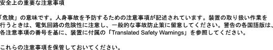
Warning Only trained and qualified personnel should be allowed to install, replace, or service this equipment. Statement 1030
Safety Warning
.
Electrical Equipment Guidelines
Follow these basic guidelines when working with any electrical equipment:
•Before beginning any procedures requiring access to the chassis interior, locate the emergency power-off switch for the room in which you are working.
•Disconnect all power and external cables before moving a chassis.
•Do not work alone when potentially hazardous conditions exist.
•Never assume that power has been disconnected from a circuit; always check.
•Do not perform any action that creates a potential hazard to people or makes the equipment unsafe.
•Carefully examine your work area for possible hazards such as moist floors, ungrounded power extension cables, and missing safety grounds.
Telephone Wiring Guidelines
Use the following guidelines when working with any equipment that is connected to telephone wiring or to other network cabling:
•Never install telephone wiring during a lightning storm.
•Never install telephone jacks in wet locations unless the jack is specifically designed for wet locations.
•Never touch uninsulated telephone wires or terminals unless the telephone line has been disconnected at the network interface.
•Use caution when installing or modifying telephone lines.
Electrostatic Discharge Prevention
Electrostatic discharge (ESD) damages equipment and impairs electrical circuitry. ESD occurs when printed circuit boards are improperly handled and results in complete or intermittent failures.
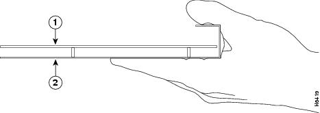
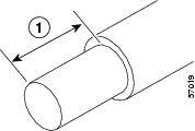
The Port Adapter Jacket Card and port adapters consist of a printed circuit board that is fixed in a metal carrier. Electromagnetic interference (EMI) shielding, connectors, and a handle are integral components of the carrier. Hold the Port Adapter Jacket Card and port adapter by its carrier edges and handle; never touch the printed circuit board or connector pins.
Do not touch the printed circuit board when handling any of the components.
Figure 2 Handling the Port Adapter Jacket Card and Port Adapter
Although the metal carrier helps to protect the Port Adapter Jacket Card or port adapter from ESD, wear a preventive antistatic strap whenever handling the Port Adapter Jacket Card and port adapter. Ensure that the strap makes good skin contact and connect the strap's clip to an unpainted chassis surface to safely channel unwanted ESD voltages to ground.
If no wrist strap is available, ground yourself by touching the metal part of the chassis.
Following are guidelines for preventing ESD damage:
•Always use an ESD wrist strap or ankle strap when installing or replacing the Port Adapter Jacket Card and port adapter. Ensure that the ESD strap makes contact with your skin.
•Handle the Port Adapter Jacket Card or port adapter by its metal carrier edges and handles; avoid touching the printed circuit board or any connector pins.
•When removing a Port Adapter Jacket Card or port adapter, place it on an antistatic surface with the printed circuit board components facing upward, or in a static shielding bag. If you are returning a port adapter or Port Adapter Jacket Card to the factory, immediately place it in a static shielding bag.
Caution Periodically check the resistance value of the antistatic strap. The measurement should be within the range of 1 and 10 megohms (Mohms).
Order of Software and Hardware Installation
Depending on the hardware you have installed, your tasks for installing a Port Adapter Jacket Card may vary. Hardware and software installation must happen in a particular order for the installation to be successful.
•If you have a network processing engine other than an NPE-G1 or NPE-G2 and an I/O controller installed, you should first install the NPE-G1 or NPE-G2. See the instructions in the "NPE-G1 and NPE-G2 Installation and Configuration Information" chapter of the Network Processing Engine and Network Services Engine Installation and Configuration document so that you do not lose your running configuration. Then return to this document for information about removing the I/O controller and installing the Port Adapter Jacket Card software image and boot image as well as the Port Adapter Jacket Card and supported port adapter.
•If you have an NPE-G1 or NPE-G2 installed, with or without an I/O controller, and are installing a Port Adapter Jacket Card, you may chose to install the Port Adapter Jacket Card and software in one of two ways:
–Remove the I/O controller and install the Port Adapter Jacket Card in two steps, powering down the router twice and powering up the router twice (Scenario 1)
–Remove the I/O controller and install the Port Adapter Jacket card in one step, powering down the router once and powering up the router once (Scenario 2)
Scenario 1
Scenario 1 requires powering down the router twice and powering up the router twice.
Step 1 Remove all the configurations that use the I/O controller ports.
Step 2 Save the running configuration to NVRAM on the NPE-G1 or NPE-G2 by executing the write command.
Step 3 Move the console and auxiliary cables from the I/O controller to the NPE-G1 or NPE-G2.
Step 4 Power down the router. (The Port Adapter Jacket Card does not support OIR.) See the "Powering Down the Router and Disconnecting Input Power" section.
Step 5 Remove the I/O controller. See the "Removing the I/O Controller Blank Panel or I/O Controller" section.
Step 6 Power on the router. See the "Reconnecting Input Power and Powering Up the Router" section.
Step 7 Log in to a router to ensure that the console and auxiliary cable connections are working.
Step 8 Install the new Cisco IOS image and boot image that support the Port Adapter Jacket Card and the port adapter.
Step 9 Set the default boot image to the newly installed boot image.
Step 10 Set the default system image to the newly installed Cisco IOS image.
Step 11 Save the configuration to NVRAM on the NPE-G1 or NPE-G2 by executing the write command.
Step 12 Power down the router. See the "Powering Down the Router and Disconnecting Input Power" section.
Step 13 Install the Port Adapter Jacket Card and a supported port adapter. See the "Installing a Port Adapter Jacket Card and Port Adapter" section.
Step 14 Power on the router. See the "Reconnecting Input Power and Powering Up the Router" section.
Scenario 2
Scenario 2 requires powering down the router once and powering up the router once.
Step 1 Remove all the configurations that use the I/O controller ports.
Step 2 Install the Port Adapter Jacket Card software and boot image.
Step 3 Set the default boot image to the Port Adapter Jacket Card boot image.
Step 4 Set the default system image to the Port Adapter Jacket Card boot image.
Step 5 Save the configuration to NVRAM on the NPE-G1 or NPE-G2 by executing the write command.
Step 6 Move the console and auxiliary cables from the I/O controller to the NPE-G1 or NPE-G2.
Step 7 Power down the router. See the "Powering Down the Router and Disconnecting Input Power" section.
Step 8 Remove the I/O controller. See the "Removing the I/O Controller Blank Panel or I/O Controller" section.
Step 9 Install the Port Adapter Jacket Card and a supported port adapter. See the "Installing a Port Adapter Jacket Card and Port Adapter" section.
Step 10 Power on the router. See the "Reconnecting Input Power and Powering Up the Router" section.
Step 11 Log in to another router to ensure that the console and auxiliary cable connections are working.
Powering Down the Router and Disconnecting Input Power
Complete the steps in the following sections to power down the router and disconnect input power.
Warning This unit might have more than one power cord. To prevent the risk of electric shock, disconnect the two power cords before servicing the unit. Statement 83
To see translations of the warnings that appear in this publication, refer to the Regulatory Compliance and Safety Information document that accompanied this device.
Powering Down the Router
To power down a Cisco 7200 VXR router, complete the following steps:
Step 1 At the rear of the router, place the power switch on the power supply in the Off (O) position. Repeat this action if a second power supply is installed in the router.
Step 2 Observe the following items:
•The yellow OK LED on the power supply goes off.
•The fans stop operating.
•The LEDs on the I/O controller go off.
•The LEDs on the port adapters go off.
Caution Wait at least 30 seconds before powering on a Cisco 7200 VXR router after you have powered it off.
This completes the procedure for powering down a Cisco 7200 VXR router.
Disconnecting AC-Input Power
To disconnect AC-input power from a Cisco 7200 VXR router complete the following steps:
Step 1 Unplug the input power cable from the power source.
Step 2 Unlock the cable-retention clip. Push up on the cable-retention clip that secures the input power cable to the router power supply.
Step 3 Unplug the input power cable from the power supply. (See Figure 3.)
Figure 3 Disconnecting Power from a Cisco 7200 VXR AC-Input Power Supply
Step 4 Repeat Step 1 through Step 4 if a second power supply is installed.
This completes the procedure for disconnecting AC-input power from a Cisco 7200 VXR router.
Disconnecting DC-Input Power
Warning Before completing any of the following steps, and to prevent short-circuit or shock hazards, ensure that power is removed from the DC circuit. To ensure that all power is off, locate the circuit breaker on the panel board that services the DC circuit, switch the circuit breaker to the off position, and tape the switch handle of the circuit breaker in the off position. Statement 322
Warning When installing the unit, the ground connection must always be made first and disconnected last. Statement 202
To see translations of the warnings that appear in this publication, refer to the Regulatory Compliance and Safety Information document that accompanied this device.
To disconnect DC-input power from a Cisco 7200 VXR router, complete the following steps:
Step 1 Turn off the power source and disconnect the -V and +V leads from the power source. You can leave the ground cable connected.
Step 2 Remove the cable tie that secures the -V, +V, and ground leads to the power supply faceplate. Save the cable tie.
Note The cable tie that accompanied your Cisco 7200 VXR router DC-input power supply can be removed and replaced on the power supply without the use of a tool. If you secured the DC-input power supply leads to the power supply faceplate using a different type of cable tie, use a wire stripper to cut that cable tie from the power supply.
Step 3 Using a 3/16-inch flat-blade screwdriver, loosen the screw below the +V lead receptacle, and pull the lead from the connector. (See Figure 4.)
Step 4 Repeat this step for the -V lead and the ground lead.
Note The color coding of the DC-input power supply leads depends on the color-coding of the DC power source at your site. Typically, green or green/yellow is used for ground, black is used for +V (return), and red or white is used for -V. Make certain that the lead color-coding you choose for the DC-input power supply matches the lead color-coding used at the DC power source.
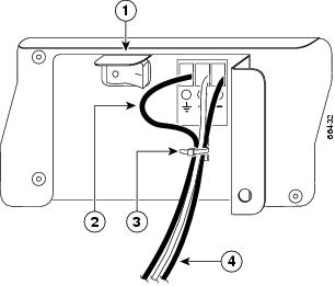
Figure 4 Disconnecting Power from a Cisco 7200 VXR DC-Input Power Supply
Step 5 Repeat Step 1 through Step 4 if a second power supply is installed.
This completes the procedure for disconnecting DC-input power from a Cisco 7200 VXR router.
Removing the I/O Controller Blank Panel or I/O Controller
For information on removing an I/O controller blank panel, see the "Removing an I/O Controller Blank Panel" section.
For information on removing an I/O controller, see the "Removing the I/O Controller" section.
Removing an I/O Controller Blank Panel
Step 1 Power down the router and disconnect the input power cable. (See the "Powering Down the Router and Disconnecting Input Power" section.)
Step 2 Attach an ESD-preventive wrist strap between you and an unfinished chassis surface.
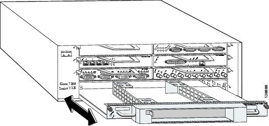
Figure 5 Removing an I/O Controller Blank Panel
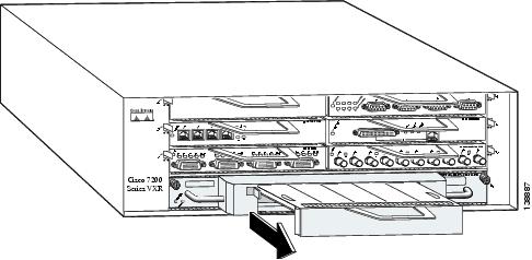
Step 3 Using a number 2 Phillips or a 3/16-inch flat-blade screwdriver, loosen the two captive installation screws on the I/O controller blank panel.
Step 4 Gently pull the I/O controller blank panel from the chassis.
Note If you have difficulty removing an I/O controller blank panel from the lowest slot of a Cisco 7200 VXR router that is rack-mounted, first remove the port adapters and processing engine from the chassis.
Removing the I/O Controller
Caution If your current hardware configuration includes a network processing engine that is older than an NPE-G1 or NPE-G2, and an I/O controller, and you are upgrading to both an NPE-G1 or NPE-G2 and the Port Adapter Jacket Card, you must copy the running configuration file to a PC card, flash disk or TFTP server before installing the NPE-G1 or NPE-G2. See the instructions in the " NPE-G1 and NPE-G2 Installation and Configuration Information " chapter of the Network Processing Engine and Network Services Engine Installation and Configuration document. Then remove the I/O controller, following the instructions in this section.
If your current hardware configuration includes an NPE-G1 or NPE-G2 and an I/O controller, do not copy the running configuration file to a flash disk, PC card, or TFTP server before removing the I/O controller. It is not necessary because the running configuration file resides in NVRAM on the NPE-G1 or NPE-G2.
To remove an I/O controller from a Cisco 7200 VXR router, complete the following steps:
Step 1 Power down the router and disconnect the input power cable. (See the "Powering Down the Router and Disconnecting Input Power" section.)
Step 2 Attach an ESD-preventive wrist strap between you and an unfinished chassis surface.
Figure 6 Cisco 7200 VXR Input/Output Controller and Ports
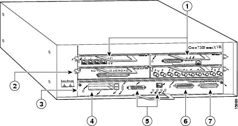
1Port adapter
5MII and RJ-45 Fast Ethernet ports
2Port adapter latch
6Auxiliary port
3I/O controller
7Console port
4PC card slots
Step 3 Disconnect the cables from the I/O controller console, auxiliary, and Fast Ethernet
ports (if present).Step 4 Remove the flash disk or PC cards (if present) from the I/O controller PC card slots.
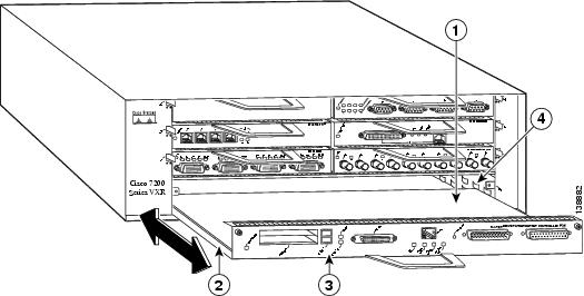
Figure 7 Removing the I/O Controller
Step 5 Using a number 2 Phillips or a 3/16-inch flat-blade screwdriver, loosen the two captive installation screws on the faceplate of the I/O controller. (See Figure 6.)
Note If you have difficulty removing the I/O controller from the lowest slot of a Cisco 7200 VXR router that is rack-mounted, remove the port adapters and processing engine from the chassis.
Step 6 Grasp the I/O controller handle and carefully pull the I/O controller from its chassis slot.
Caution Handle the I/O controller by the carrier edges and handle only; never touch the printed circuit board components or connector pins. (See Figure 2.)
Step 7 Place the I/O controller on an antistatic surface, or in a static shielding bag, with its components facing upward. If you are returning the I/O controller to the factory, immediately place it in a static shielding bag.
This completes the procedure for removing an installed I/O controller.
Installing a Port Adapter Jacket Card and Port Adapter
Follow these steps to install a Port Adapter Jacket Card and port adapter:
Note Online insertion and removal (OIR) is not supported on the Port Adapter Jacket Card. OIR is supported on the port adapter. You must have the chassis powered off to install or remove the Port Adapter Jacket Card.
Step 1 Power off the router if you have not already done so. See the "Powering Down the Router and Disconnecting Input Power" section.
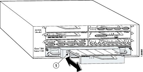
Figure 8 Installing a Port Adapter Jacket Card
Note The port adapter may be installed in the Port Adapter Jacket Card and both installed into the router together, or the installation may be done in two steps with the Port Adapter Jacket Card being installed first, and then the port adapter.
Note The following procedures describe the Port Adapter Jacket Card and port adapter being installed in two steps.
Step 2 Align the Port Adapter Jacket Card tray with the slot guides in the chassis.
Step 3 Insert the Port Adapter Jacket Card until it is fully seated.
Step 4 Tighten the captive installation screws found on the top corners of the Port Adapter Jacket Card.
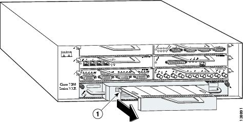
Figure 9 Removing the Port Adapter Blank Panel
Step 5 Remove any port adapter blank panel that may be in place.
a. Move the lock lever on the top left corner of the Port Adapter Jacket Card until the port adapter blank panel releases.
b. Pull the port adapter blank panel from the Port Adapter Jacket Card.
Figure 10 Installing a Port Adapter in the Port Adapter Jacket Card
Step 6 Insert the port adapter into the Port Adapter Jacket Card until it is fully seated.
Step 7 Move the port adapter lock lever to the locked position.
Step 8 If your removed the processing engine and port adapters, replace them in a bottom-to-top order.
You have completed installing the Port Adapter Jacket Card and port adapter and are ready to connect power to the router and power on. See the "Reconnecting Input Power and Powering Up the Router" section.
Removing a Port Adapter and Port Adapter Jacket Card
Note Online insertion and removal (OIR) is not supported on the Port Adapter Jacket Card. OIR is supported on the port adapter.
If you are removing only the port adapter, you do not have to power down the router.
Figure 11 Removing a Port Adapter
Step 1 Remove the port adapter by pressing the lock lever until the port adapter releases.
Step 2 Pull the port adapter from the Port Adapter Jacket Card.
Step 3 If you are not planning to remove the Port Adapter Jacket Card, replace the port adapter or insert a port adapter blank panel in the Port Adapter Jacket Card to ensure proper airflow through the router.
Figure 12 Removing the Port Adapter Jacket Card
Note If you have difficulty removing the Port Adapter Jacket Card from the lowest slot of a Cisco 7200 VXR router that is rack-mounted, first remove the port adapters and network processing engine from the chassis, and then remove the Port Adapter Jacket Card.
Step 4 If you are removing the Port Adapter Jacket Card, loosen the captive installation screws found at the top left corners of the Port Adapter Jacket Card and, using the handles on the Port Adapter Jacket Card, pull the Port Adapter Jacket Card from the chassis.
Step 5 Replace the Port Adapter Jacket Card with an I/O controller blank panel or another Port Adapter Jacket Card to ensure proper airflow through the router.
Step 6 If the Port Adapter Jacket Card has been replaced, insert a port adapter or a port adapter blank panel into the Port Adapter Jacket Card to ensure proper airflow through the router.
Step 7 Tighten the captive installation screws.
Step 8 If you removed the processing engine or port adapters from the chassis, replace them in a bottom-to-top order.
You have finished removing the port adapter and Port Adapter Jacket Card and are ready to connect power and power on. See the "Reconnecting Input Power and Powering Up the Router" section.
Reconnecting Input Power and Powering Up the Router
The following procedures explain how to reconnect input power to a Cisco 7200 VXR router, power up the router, and verify a successful system boot.
Warning Read the installation instructions before you connect the system to its power source.
Statement 10
To see translations of the warnings that appear in this publication, refer to the Regulatory Compliance and Safety Information document that accompanied this device.
Reconnecting AC-Input Power
To reconnect AC-input power to a Cisco 7200 VXR router, complete the following steps:
Step 1 At the rear of the router, check that the power switch on the power supply is in the Off (O) position.
Step 2 Slide the cable-retention clip up. away from the AC receptacle, and plug in the power cable. (See Figure 13.)
Step 3 Secure the cable in the power supply AC receptacle by sliding the cable-retention clip down, until it snaps around the connector. The cable-retention clip provides strain relief for the AC power cable.
Figure 13 Connecting AC-Input Power to a Cisco 7200 VXR Router
1Power switch
4Power cable-retention clip
2Power cord
5Handle with hole for cable tie
3PWR OK LED
Step 4 Plug the AC power supply cable into the AC power source.
Note For Cisco 7200 VXR routers, each AC-input power supply operating at 120 VAC requires a minimum of 5A service.
We recommend powering Cisco 7200 VXR routers from a 120 VAC, 15A receptacle United States (240 VAC, 10A international) at the power source.
Step 5 Repeat Step 1 through Step 4 if a second power supply is installed.
This completes the steps for reconnecting AC-input power to a Cisco 7200 VXR router. Proceed to the "Powering Up the Router" section.
Reconnecting DC-Input Power
Note The color-coding of the DC-input power supply leads depends on the color-coding of the DC power source at your site. Typically, green or green/yellow is used for ground, black is used for +V (return), and red or white is used for -V. Make certain the lead color-coding you choose for the DC-input power supply matches the lead color-coding used at the DC power source.
Warning Before completing any of the following steps, and to prevent short-circuit or shock hazards, ensure that power is removed from the DC circuit. To ensure that all power is off, locate the circuit breaker on the panel board that services the DC circuit, switch the circuit breaker to the off position, and tape the switch handle of the circuit breaker in the off position. Statement 322
To see translations of the warnings that appear in this publication, refer to the Regulatory Compliance and Safety Information document that accompanied this device.
Warning When installing the unit, the ground connection must always be made first and disconnected last. Statement 42
To see translations of the warnings that appear in this publication, refer to the Regulatory Compliance and Safety Information document that accompanied this device.
To reconnect DC-input power to a Cisco 7200 VXR router, complete the following steps:
Step 1 Ensure that the -V and +V leads are disconnected from the power source.
Step 2 At the rear of the router, check that the power switch on the power supply is in the Off (O) position. (See Figure 14.)
Figure 14 Connecting DC-Input Power to a Cisco 7200 VXR Router
Step 3 If necessary, use a wire stripper to strip approximately 0.55 inch (14 mm) from the -V, +V, and ground leads. (See Figure 15.)
Figure 15 Stripping the DC-Input Leads
Step 4 Attach the ground lead. Insert the stripped end of the ground lead all the way into the ground lead receptacle on the DC-input power supply, and tighten the receptacle screw using a 3/16-inch flat-blade screwdriver. (See Figure 14.)
Step 5 Insert the stripped end of the +V lead all the way into the +V lead receptacle and tighten the receptacle screw using the 3/16-inch flat-blade screwdriver. Repeat Step 5 for the -V lead.
Note Make sure that the entire stripped end of each lead is inserted all the way into its receptacle. If any exposed wire at the stripped end of a lead is visible after you insert the lead into its receptacle, remove the lead from the receptacle, use the wire stripper to cut the stripped end of the lead, and repeat Step 3 through Step 5.
Step 6 After tightening the receptacle screw for the ground, +V, and -V DC-input leads, secure the leads to the power supply faceplate. Use the cable tie you saved earlier to secure the three leads.
Note For Cisco 7200 VXR routers, when securing the ground, +V, and -V DC-input leads to the power supply faceplate, leave a small service loop in the ground lead to ensure that it is the last lead to disconnect from the power supply if a great deal of strain is placed on all three leads. (See Figure 14.)
Step 7 Connect the ground, +V, and -V leads to the power source.
Note For Cisco 7200 VXR routers, each DC-input power supply operating at - 48 VDC in North America requires a minimum of 13A service. Each DC-input power supply operating at -60 VDC in the European Union requires a minimum of 8A service.
Warning This product relies on the building's installation for short-circuit (overcurrent) protection. Ensure that a listed and certified fuse or circuit breaker, 35A minimum 60 VDC, is used on all current-carrying conductors.
To see translations of the warnings that appear in this publication, refer to the Regulatory Compliance and Safety Information document that accompanied this device.
Step 8 Repeat Step 1 through Step 7 if a second power supply is installed.
This completes the steps for reconnecting DC-input power to a Cisco 7200 VXR router.
Powering Up the Router
To power up a Cisco 7200 VXR router that has an installed AC-input or DC-input power supply, complete the following steps:
Step 1 Check for the following:
•Each port adapter is inserted in its slot, and its respective port adapter lever or cable-retention clip is in the locked position.
•The network processing engine or network services engine and the Port Adapter Jacket Card are inserted in their respective slots, and their captive installation screws are tightened.
•All network interface cables are connected to the port adapters.
•If present, a flash memory card is properly installed in its PC card slot.
•Each AC-input power cable is connected and secured with the cable-retention clip (AC-input power supplies only).
•Each DC lead is connected and secured to the power supply faceplate with a cable tie (DC-input power supplies only).
•Each DC lead is connected and secured to the power source (DC-input power supplies only).
•Ensure that the tape (that you applied earlier) is removed from the circuit breaker switch handle, and power is restored by moving the circuit breaker handle to the On position (DC-input power supplies only).
•The console terminal is turned on.
Step 2 At the rear of the router, place the power switch on the power supply in the On ( | ) position. Repeat this step if a second power supply is installed in the router. The yellow OK LED on the power supply comes on.
Step 3 Listen for the fans; you should immediately hear them operating.
Step 4 During the boot process, observe the system LEDs. The LEDs on most of the port adapters go on and off in irregular sequence. Some may come on, go out, and come on again for a short time.
Step 5 Observe the initialization process. When the system boot is complete (a few seconds), the network processing engine begins to initialize the port adapters and the I/O controller. During this initialization, the LEDs on each port adapter behave differently (most flash on and off). The ENABLED LED on each port adapter comes on when initialization is completed, and the console screen displays a script and system banner similar to the following display:
Cisco Internetwork Operating System SoftwareIOS (tm) 7200 Software (C7200-J-M), Version 11.1(9) [kpfjrgiu 100]Copyright (c) 1986-1996 by cisco Systems, Inc.Compiled Sun 21-Apr-96 04:10 byStep 6 Check the Port Adapter Jacket Card to see that the PWR LED and ENABLE LEDs are on.
This completes the procedures for connecting input power and powering up the router.
Related Documentation
Your Cisco 7200 VXR router and the Cisco IOS software running on it contain extensive features and functionality, which are documented in the following resources:
•Cisco 7200 Series Routers Documentation Roadmap for a list of all Cisco 7200 series routers documentation and troubleshooting tools and information.
•Cisco 7200 Series Routers Port Adapter Documentation Roadmap for a list of all Cisco 7200 series routers-supported port adapter documentation.
•Cisco 7200 Series Routers Troubleshooting Documentation Roadmap for links to troubleshooting tools, utilities, and Tech Notes.
Obtaining Documentation, Obtaining Support, and Security Guidelines
For information on obtaining documentation, obtaining support, providing documentation feedback, security guidelines, and also recommended aliases and general Cisco documents, see the monthly What's New in Cisco Product Documentation, which also lists all new and revised technical documentation at: http://www.cisco.com/en/US/docs/general/whatsnew/whatsnew.html.
This document is to be used in conjunction with the documents listed in the "Related Documentation" section.
© 2007 Cisco Systems, Inc. All rights reserved.