Using the Flash Disk
Available Languages
Table Of Contents
System Memory and Software Image Functions and Interactions
Information About Flash Disk OIR
Electrical Equipment Guidelines
Electrostatic Discharge Prevention
Installing and Removing a Flash Disk in Vertically Oriented Systems
Installing and Removing a Flash Disk in Horizontally Oriented Systems
Installing and Removing a Flash Disk in Cisco 7100 Series Routers
Installing and Removing a Flash Disk in All Other Horizontally Oriented Systems
Enabling Booting from a Flash Disk
Making a Flash Disk-Based Software Image the Bootable Software Image
Obtaining Documentation, Obtaining Support, and Security Guidelines
Using the Flash Disk
Product Numbers: MEM-I/O-FLD64M=, MEM-I/O-FLD128M=, MEM-7100-FLD48M=, MEM-7100-FLD128M=, MEM-7201-FLD256=, MEM-COMP-FLD64M=, MEM-COMP-FLD128M=, MEM-NPE-G1-FLD64=, MEM-NPE-G1-FLD128=, MEM-NPE-G1-FLD256=, MEM-NPE-G2-FLD256=, MEM-RSP8-FLD48M(=), MEM-RSP8-FLD64M(=), MEM-RSP8-FLD128M(=), MEM-RSP16-FLD48M(=), MEM-RSP16-FLD64M(=), MEM-RSP16-FLD128M(=)
Document Revision History
The Document Revision History beginning with online part number OL-6452-02, records technical changes in this document.
Introduction
This document provides instructions for installing, removing, and using Flash Disks in Cisco 7100, Cisco 7200 (including Cisco 7201), and Cisco 7500 products that have PC Card slots—formerly called Personal Computer Memory Card International Association (PCMCIA) slots. (For a list of Cisco products that support the Flash Disk—and how they support it—see the "Hardware Requirements" section).
Flash Disks and the CompactFlash Disk provide storage space for your configuration files, Cisco IOS software images, and so forth. (Also see the "Product Description" section.)
Contents
This configuration note includes the following sections:
•
Obtaining Documentation, Obtaining Support, and Security Guidelines
Related Documentation
Your Cisco router and the Cisco IOS software running on it contain extensive features and functionality, which are documented online and in the following resources:
•

Note
Translated documentation is available at the following URL: http://www.cisco.com/public/countries_languages.shtml
For hardware installation and maintenance information, regulatory compliance and safety information, and troubleshooting information, refer to the following documents:
•
•
•
Installation Prerequisites
This section describes installation prerequisites you should observe before you can use the Flash Disk or CompactFlash Disk in your system, and includes the following subsections:
•
Software Requirements
The Flash Disk provides file storage for the Cisco products listed in the section "Hardware Requirements" if these systems are running the applicable Cisco IOS release listed in Table 1, Table 2, or a later release.
Table 2 Minimum Supported IOS Release for the CompactFlash Disk
Cisco 7200 VXR router with NPE-G1
12.2.(4)BX
Using the Flash Disk requires that you upgrade the boot image to Cisco IOS Release 12.0(2) or a later release of 12.0. Refer to the "Sample Upgrade Process" section for upgrade instructions. (For additional information regarding boot image requirements, see the "Compatibility Requirements" section.)
Hardware Requirements
You can use a CompactFlash Disk for file storage on the NPE-G1 or NPE-G2 used in the
Cisco 7200 VXR routers, and the Cisco 7201. You must use a CompactFlash Disk for Cisco IOS software configuration file storage.You can use the Flash Disk for file storage in the PC Card slots of the Input/output (I/O) controller used in Cisco 7200 series systems (Cisco 7202, Cisco 7204, Cisco 7204VXR, Cisco 7206, and Cisco 7206VXR) and Cisco uBR7200 series universal broadband routers.
Note
•
•
For convenience throughout this publication, the I/O controller, Route Switch Module (RSM), network processing engine (NPE), and RSP8 are referred to as the system processor. Specific differences are clearly noted.
Tools and Parts Required
You need some or all of the following tools and parts to install a Flash Disk:
•
•
•
•
•
–
–
•
•
(See the "Hardware Requirements" section for a system list.)–
(See the "Hardware Requirements" section for a system list.)–
Compatibility Requirements
This section discusses Flash Disk compatibility and use between supported systems.
In order to boot a Cisco IOS software image from the Flash Disk, when the system is executing from the ROM monitor software image, your ROM monitor software image and your boot image must be from one of the minimum Cisco IOS releases listed in Table 1. Use the show version or show hardware commands to verify that your RSP8-based system is running these software images. The NPE-300 or later version installed in the Cisco 7204VXR and Cisco 7206VXR systems and the Cisco 7201 meets these requirements.
The format command places a processor-specific library on the Flash Disk so that the ROM monitor software can read the Flash memory media. If you plan to use the boot or dir commands at the ROM monitor prompt (rommon>), you might need to reformat your Flash Disk if it was not already formatted on a like system processor.
Note
To ensure Flash Disk system compatibility, observe the following guidelines:
•
•
•
•
For simple file storage and retrieval functions, Flash Disks can be interchanged between and used in any system listed in the "Hardware Requirements" section.
Note
System Memory and Software Image Functions and Interactions
The read-only memory (ROM) monitor image on your system performs important functions, such as running a brief set of system diagnostics, and initializing the hardware. This image gains control at reset or power on, or after a nonrecoverable event (such as a bus error). The ROM monitor software image has a rudimentary user interface that is recognizable by way of the ROM monitor prompt (rommon>). The ROM monitor software image has console drivers and trap handlers for parity and bus errors; however, the ROM monitor does not have any network interface code and it cannot boot an image over the network.
Note
By default, and as a result of a reset or power on, the ROM monitor loads the boot image from boot flash memory. If the ROM monitor cannot find a bootable image in boot flash memory, it searches the PC Card-based devices (such as linear Flash memory cards or Flash Disks) for the first bootable image. Normally, this would be the boot image (such as rsp-boot-mz or c7200-boot-mz).
The boot image, when loaded, looks in the boot environment variables—stored in nonvolatile random-access memory (NVRAM)—to determine the location of the Cisco IOS software image and the configuration to use. If boot environment variables are not defined, the system will boot the first image found on a Flash Disk, or if no such image is found, it will boot the first image found on a linear Flash memory card.
The operation of the boot environment variables is described in the "Boot Environment Variables" section, which follows.
Boot Environment Variables
The contents of the boot environment variables, which are stored in the configuration file in NVRAM, determine the actions your system takes on bootup. To see the current settings of these variables, use the show bootvar command as follows:
Router> show bootvarBOOT variable =CONFIG_FILE variable =Current CONFIG_FILE variable =BOOTLDR variable does not existConfiguration register is 0x100Following are explanations for each of these boot environment variables:
•
Enter configuration mode and specify a filename and PC Card slot from which to boot using the configure terminal and boot system commands as follows:
Router# configure terminalEnter configuration commands, one per line. End with CTRL-Z.System(config)# boot system flash disk0:rsp-p-mz.12-0The result of this configuration file entry is that the BOOT variable is disk0:rsp-p-mz.12-0.
•
Router# configure terminalEnter configuration commands, one per line. End with CTRL-Z.System(config)# boot config disk0:configfileThe result of this configuration file entry is that the CONFIG_FILE variable is disk0:configfile.
•
Router# configure terminalEnter configuration commands, one per line. End with CTRL-Z.System(config)# boot bootldr bootflash:c7200-boot-mzThe result of this configuration file entry is that the BOOTLDR variable is bootflash:c7200-boot-mz.
•
Router# configure terminalEnter configuration commands, one per line. End with CTRL-Z.System(config)# config-register 0x102The result of this configuration file entry is that the configuration register is set to hexadecimal 0x102. Please see the Cisco 7200 VXR Installation and Configuration Guide (Chapter 4, "Observing System Startup and Performing a Basic Configuration") at http://www.cisco.com/univercd/cc/td/doc/product/core/7200vx/72vxicg/configvx.htm for more information about the configuration register.
Sample Upgrade Process
This section applies to users who want to use Flash Disks for simple file storage.
Step 1
Step 2
Step 3
Step 4
Step 5
Step 6
Step 7
You should now be able to store configuration files and Cisco IOS software images on your Flash Disk.
If you have an NPE-300-based system (or a later processor), you should now be able to boot from any Cisco IOS software images you store on your Flash Disk.
Note
Information About Flash Disk OIR
Online insertion and removal (OIR) is possible with Flash Disks. However, it is best to avoid certain situations when removing a Flash Disk could lead to corrupting the Flash Disk or to a circumstance where no image is available for the router to boot from. Use this information to help decide when to insert or remove a Flash Disk:
•
•
•
•
Safety Guidelines
Following are safety guidelines that you should follow when working with any equipment that connects to electrical power, or which might be sensitive to electrostatic discharge (ESD) damage.
Electrical Equipment Guidelines
Follow these basic guidelines when working with any electrical equipment:
•
•
•
•
•
•
Electrostatic Discharge Prevention
Electrostatic discharge (ESD) damage, which can occur when electronic cards or components are improperly handled, results in complete or intermittent failures.
Use the following guidelines for preventing ESD damage:
•
•

Caution
Product Description
Flash Disks are Flash memory-based devices that conform to the PC Card (formerly PCMCIA) standard and present an ATA (AT Attachment) interface to the system. This interface complies with the ANSI ATA Interface Document X3T13.1153 D Rev. 9 specification.
The Flash Disk is more flexible than linear Flash memory because the Flash Disk has controller circuitry that allows it to emulate a hard disk and automatically maps out bad blocks and performs automatic block erasure. Further, the Flash Disk provides the capability to allocate noncontiguous sectors, which eliminates the need for the squeeze command (previously required with linear Flash memory cards).
The Flash Disk provides increased Flash-based memory space—48 to 128 MB—for storage of system configuration files, Cisco IOS software images, and other types of system-related files. Table 3 provides memory information for the Flash Disk and Table 4 provides memory information for the CompactFlash Disk.
Table 3 Flash Disk Memory Options
48 MB
MEM-7100-FLD48M, MEM-RSP8-FLD48M, MEM-RSP16-FLD481
64 MB
MEM-I/O-FLD64M, MEM-RSP8-FLD64M, MEM-RSP16-FLD64M
128 MB
MEM-I/O-FLD128M, MEM-7100-FLD128M, MEM-RSP8-FLD128M, MEM-RSP16-FLD128M1
1 These products are also available as Flash Disk upgrades. To order an upgrade, add an equal sign (=) after the Product Number, for example, MEM-I/O-FLD128M=.
Note
The Cisco IOS File System feature provides a single interface to all file systems your system uses:
•
•
•
Note
Installing a Flash Disk
The Flash Disk is a Type 2 PC Card device. This means that you can install up to two Flash Disks in system processors with two PC Card slots; there are no PC Card slot-height restrictions related to the Flash Disk. Further, the PC Card slots in which you install the Flash Disk are either vertically oriented or horizontally oriented, depending on the system you are using and the system processor installed in it; therefore, this section provides the following two Flash Disk installation procedures:
•
•
Determine how your system is oriented, and then use the appropriate procedure.
Use the show version command to verify that a Flash Disk-compatible version of Cisco IOS software is running on your system:
System> show versionCisco Internetwork Operating System SoftwareIOS (tm) 7200 Software (C7200-J-M), Released Version 12.0(2)Copyright (c) 1986-1998 by cisco Systems, Inc.(Additional displayed text omitted from this example.)Installing and Removing a Flash Disk in Vertically Oriented Systems
The procedure in this section is for inserting and ejecting a Flash Disk in systems in which the PC Card slots are vertically oriented. The procedure is generic and can be used for a Flash Disk in either PC Card slot position (slot 0 or slot 1). You do not need to turn off system power for this procedure.
Use the following procedure to install and eject a Flash Disk in systems with vertically oriented PC Card slots:
Step 1
Step 2
Hold the Flash Disk with its connector end toward the PC Card slot and its front label facing to the right.
The Flash Disk is keyed and cannot be seated the wrong way. The ejector button does not pop out if the Flash Disk is not completely inserted.
Step 3
(See b of Figure 1.)The Flash Disk does not insert all the way inside the PC Card slot. A portion of the Flash Disk remains outside the slot. Do not attempt to force the Flash Disk past this point.
Figure 1 Installing and Ejecting a Flash Disk in a Vertically Oriented System
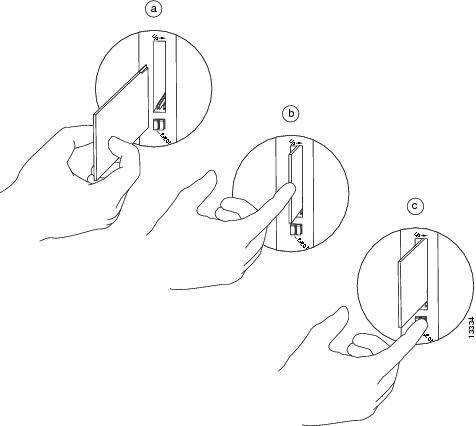
Step 4
Step 5
This completes the procedure for installing and removing a Flash Disk in a vertically oriented system. Proceed to the "Working with a Flash Disk" section.
Installing and Removing a Flash Disk in Horizontally Oriented Systems
The procedures in this section describe how to insert and eject a Flash Disk in systems in which the PC Card slots are horizontally oriented. The following two procedures are discussed:
•
This procedure is specific to Cisco 7100 series routers. Use it for a Flash Disk in either horizontally oriented PC Card slot position (slot 0 or slot 1) on your Cisco 7100 series router.
•
This procedure is generic for all other horizontally oriented systems. Use it for a Flash Disk in either horizontally oriented PC Card slot on your system—PC Card slot 0 or slot 1.
Determine the system you have and use the appropriate procedure. (For a list of systems that support the Flash Disk, see the "Hardware Requirements" section.) You do not need to turn off system power for these procedures.
Note
(See a and b in Figure 3.)
Installing and Removing a Flash Disk in Cisco 7100 Series Routers
Use the following procedure to install and eject a Flash Disk in a Cisco 7100 series router:
Step 1
Step 2
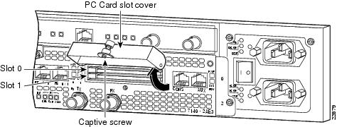
To ensure protection from electromagnetic interference (EMI), the PC Card slots have a cover that is secured with a captive screw.
Figure 2 PC Card Slots on a Cisco 7100 Series Router—Partial Rear View of Router
Step 3
Step 4
The Flash Disk is keyed and cannot be seated the wrong way. The ejector button does not pop out if the Flash Disk is not completely inserted.
Figure 3 Installing and Ejecting a Flash Disk in a Cisco 7100 Series Router
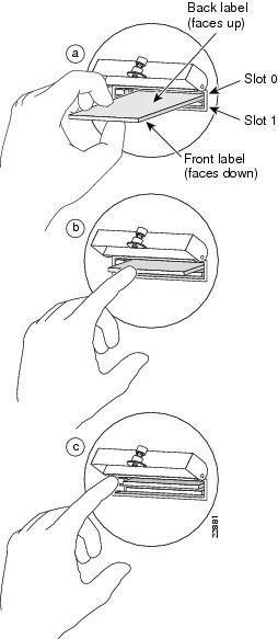
Step 5
(See b of Figure 3.)The Flash Disk does not insert all the way inside the PC Card slot; a portion of the Flash Disk remains outside the slot. Do not attempt to force the Flash Disk past this point.
Step 6
Step 7
Step 8
Step 9
This completes the procedure for installing and removing a Flash Disk in a Cisco 7100 series router. Proceed to the "Working with a Flash Disk" section.
Installing and Removing a Flash Disk in All Other Horizontally Oriented Systems
Use the following procedure to install and eject a Flash Disk in all other systems that have horizontally oriented PC Card slots:
Step 1
Step 2
Figure 4 Installing and Ejecting a Flash Disk in a Horizontally Oriented System
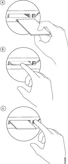
Step 3
The Flash Disk is keyed and cannot be seated the wrong way. The ejector button does not pop out if the Flash Disk is not completely inserted.
Step 4
(See b of Figure 4).The Flash Disk does not insert all the way inside the PC Card slot; a portion of the Flash Disk remains outside the slot. Do not attempt to force the Flash Disk past this point.
Step 5
(See c of Figure 4.)Step 6
This completes the procedure for installing and removing a Flash Disk in a horizontally oriented system. Proceed to the "Working with a Flash Disk" section.
Working with a Flash Disk
This section provides basic instructions for working with a Flash Disk in your system. Detailed descriptions of more complex Flash Disk options and the Cisco IOS File System feature are beyond the scope of this publication and can be found in the following Cisco IOS Release 12.x publications:
•
•
Note
This section includes the following subsections:
•
•
You can only boot from a Cisco IOS software image stored in a Flash Disk using the following systems: RSP8-based Cisco 7500 series systems, and NPE-300-based systems. (The NPE-300-based systems include the Cisco 7204VXR and the Cisco 7206VXR routers.)
In all other systems, booting from Flash Disk-based Cisco IOS software images is not supported. You can use Flash Disks for simple storage in all the systems listed in the "Hardware Requirements" section.Software Command Overview
This section lists some of the basic software commands you can use with the Flash Disk. Examples of these commands are included in the sections that follow.
The Flash Disk and other memory devices and locations in your system are defined as file systems, which are locations where you can store, use, or retrieve files and software images. (See the brief discussion about the Cisco IOS File System feature in the "Product Description" section.)
You can use Flash Disks in either one or both of the PC Card slots on your system processor, or you can use one Flash Disk in one PC Card slot and a linear Flash memory card in the adjacent PC Card slot. Flash Disks in PC Card slots 0 and 1 are referred to as disk0: and disk1:, respectively, whereas linear Flash memory cards in PC Card slots 0 and 1 are referred to as slot0: and slot1:, respectively.
The following partial output of the show file systems command shows a sample system with a Flash Disk—called disk0:—installed in PC Card slot 0 and a linear Flash memory card—called slot1:—installed in PC Card slot 1:
System# show file systemsFile Systems:Size(b) Free(b) Type Flags Prefixes(Additional displayed text omitted from this example.)48755200 48747008 flash rw disk0:7995392 4717276 flash rw slot1:Table 5 lists the software commands that you can use with the Flash Disk.
Note
For a discussion of additional command arguments, refer to the Configuration Fundamentals Command Reference document, in the chapter "File Management Commands."
Using Software Commands
This section provides examples of some of the basic software commands you can use with the Flash Disk. See Table 5 for optional arguments you can use with some of the following commands:
Using the show Command
To display information about Flash Disk format and geometry, use the show [disk0: | disk1:] command:
System# show disk0:******** ATA Flash Card Geometry/Format Info ********ATA CARD GEOMETRYNumber of Heads: 16Number of Cylinders 840Sectors per Cylinder 32Sector Size 512Total Sectors 430080ATA CARD FORMATNumber of FAT Sectors 105Sectors Per Cluster 16Number of Clusters 26822Number of Data Sectors 429536Base Root Sector 338Base FAT Sector 128Base Data Sector 370Router#In this example:
•
•
•
•
•
•
•
•
•
•
•
•
Using the pwd Command
To determine which PC Card slot you are accessing, use the pwd command:
System# pwddisk0:/System#The preceding example indicates that you are currently in the working directory called disk0:, which is the Flash Disk in PC Card slot 0.
Using the cd Command
To move back and forth between installed Flash Disks, use the cd command by defining a specific path name. Then to verify your working directory, use the pwd command:
System# cd disk1:System# pwddisk1:/System# cd disk0:System# pwddisk0:/You can also move up (or back) one level in the Flash Disk directory hierarchy using the cd .. command, and then verify your working directory with the pwd command:
System# pwddisk1:daily_dir/System# cd ..System# pwddisk1:/System#Using the dir Command
To list the directory structure and contents of the Flash Disk from which you are currently working, use the dir command with no arguments:
System# dirDirectory of disk1:/1 drw- 0 Jul 25 1998 10:23:11 daily_dir2 drw- 0 Jul 25 1998 10:28:37 access_lists48755200 bytes total (48742912 bytes free)System#Note that the size of the Flash Disk is shown in the output of the dir command. (A 48-MB Flash Disk is shown in this example.) You can also view the contents of other directories and file systems using specific optional arguments with the dir command. (See Table 4.)
Using the format Command
To format a new Flash Disk, use the format [disk0: | disk1:] command.
Note
Caution
Note
Use the following procedure to format a new Flash Disk using the format command. (The procedure assumes you have already booted your system.)
Step 1
If slot 0 is not available, use slot 1, but in the following step use the format disk1: command, not the format disk0: command, or you will format the Flash Disk that is being used in slot 0.
Step 2
System# format disk0:Format operation may take a while. Continue? [confirm]Format operation will destroy all data in `disk0:'. Continue? [confirm]Format:Drive communication & 1st Sector Write OK...Writing Monlibsectors............................................................................................Monlib write completeFormat:All system sectors written. OK...Format:Total sectors in formatted partition:81760Format:Total bytes in formatted partition:49861120Format:Operation completed successfully.Format of disk0:complete
Note
The new Flash Disk is now formatted and ready to use in the system on which you formatted it.
(For specific formatting and compatibility requirements, see the "Compatibility Requirements" section.)Using the copy Command
To copy an image from a Flash Disk to another file system or from another file system to the Flash Disk, use the copy command:
copy [tftp: | bootflash: | disk0: | disk1:]source-filename [tftp: | bootflash: | disk0: | disk1:]destination-filename
In this example:
•
•
•
You do not need to change the filename; this is an option.
The following assumptions are made for this command:
•
•
•
An Ethernet interface is used in the examples that follow.
•
Note
Note
Use the following procedure to copy a file (called new.image in this example) located on a Flash Disk—called disk1:—in PC Card slot 1 to the Flash Disk—called disk0:—in PC Card slot 0:
Step 1
Step 2
System> enablePassword:System# copy disk1:new.image disk0:new.image3393 bytes copied in 0.548 secs#System#In the preceding example, the 3393-byte file new.image was copied to the Flash Disk in PC Card slot 0 in approximately one-half second.
Step 3
System# pwddisk0:/System# dirDirectory of disk0:/1 -rw- 3393 Jul 26 1998 17:44:47 new.image48755200 bytes total (48747008 bytes free)System#
Using the mkdir Command
To create a directory on the Flash Disk, use the mkdir command. The following example shows how to create a directory called daily_dir on the Flash Disk in PC Card slot 1, and then verify that it was created:
System# mkdir disk1:daily_dirCreated dir disk1:daily_dirSystem# dirDirectory of disk1:/1 drw- 0 Jul 25 1998 10:15:43 daily_dir48755200 bytes total (48751104 bytes free)System#
Note
For example, if you placed the file itsa.file into the directory daily_dir on the Flash Disk in PC Card slot 1, you must designate the entire directory path as follows: disk1:daily_dir/itsa.file. Otherwise, the system might not be able to locate this file.
Using the rmdir Command
To remove a directory from the Flash Disk, use the rmdir command. The following example shows how to remove the directory daily_dir from the Flash Disk in PC Card slot 1, and then verify that it was removed:
System# rmdir disk1:daily_dirDelete disk1:daily_dir? [confirm] yRemoved dir disk1:daily_dirSystem# dirDirectory of disk1:/No files in directory.48755200 bytes total (48751104 bytes free)System#Using the delete Command
To delete a file from a Flash Disk, use the delete command. Use the dir command to find the file you want to delete, and then use the delete command to delete it.
The following example shows how to find a file (called fun1) on the Flash Disk in PC Card slot 0, delete the file, and then verify that it is deleted:
Step 1
System# dirDirectory of disk0:/1 drw- 0 May 10 1998 09:54:53 fun148755200 bytes total (48742912 bytes free)Step 2
System# delete disk0:fun1Step 3
System# dirDirectory of disk0:/No files in directory.48755200 bytes total (48742912 bytes free)System#
Enabling Booting from a Flash Disk
This section explains how to enable booting from a Flash Disk.
To enable booting from a Flash Disk, set configuration register bits 3, 2, 1, and 0 to a value between 2 and 15 in conjunction with the boot system [disk0: | disk1:]filename configuration command. This section includes only descriptions of boot commands specific to the Flash Disk. (You can use either the slotn: argument or the diskn: argument for boot commands.)
Following are definitions of the various Flash Disk-related boot commands:
•
•
•
•
Note
For example, notice the difference in the following correct and incorrect commands:
System(config)# boot flash system disk0:myfileBased on the preceding correct command, the system boots the file specified (myfile).
System(config)# boot flash system disk0: myfileBased on the preceding incorrect command, the system finds the filename field blank because there is a space after disk0:. In this case, the system ignores the filename argument and boots the first file on the Flash Disk, which might not be the file called myfile.
Use the following procedure to enable booting the file myfile from a Flash Disk:
Step 1
System# configure terminalEnter configuration commands, one per line. End with CTRL-Z.System(config)# boot system flash disk0:myfileStep 2
System(config)# config-reg 0x2102This command, with the hexadecimal value 0x2102, results in the following:
•
•
•
Step 3
System(config)#Crtl-ZSystem#Step 4
System# copy system:running-config nvram:startup-config
Making a Flash Disk-Based Software Image the Bootable Software Image
This section explains how to make a Flash Disk-based Cisco IOS software image a bootable image.
After you copy a software image to the Flash Disk, use the following series of commands to make the image bootable (the file named new.image in this example). The software image in this example is located on the Flash Disk in PC Card slot 0. Note that the config-register command is also a part of this command sequence because you must set the configuration register to 0x2102 to enable loading an image from the Flash Disk.
System# config terminalSystem(config)# no boot systemSystem(config)# boot system flash disk0:new.imageSystem(config)# config-register 0x2102Ctrl-ZSystem# copy system:running-config nvram:startup-configSystem# reloadWhen the system reloads, it boots the image new.image from the Flash Disk in slot 0.
Obtaining Documentation, Obtaining Support, and Security Guidelines
For information on obtaining documentation, obtaining support, providing documentation feedback, security guidelines, and also recommended aliases and general Cisco documents, see the monthly What's New in Cisco Product Documentation, which also lists all new and revised technical documentation at: http://www.cisco.com/en/US/docs/general/whatsnew/whatsnew.html.
This document is to be used in conjunction with the appropriate documents available for use with your router.

 Feedback
Contact Cisco
- Open a Support Case

- (Requires a Cisco Service Contract)