Cisco 7206 Quick Reference Card
Available Languages
Table Of Contents
Quick Reference
For Cisco 7206 Installation
Quick Reference
For Cisco 7206 Installation
These installation tasks should be completed in the following order:
1
Rack-mounting the router
2
3
For detailed instructions about rack-mounting, cabling, and starting the Cisco 7206, refer to the publication Cisco 7206 Installation and Configuration Guide and the port adapter configuration notes that shipped with your router.
Cisco 7200 series documentation and additional literature are available in a CD-ROM package, which ships with your router.
You can also access Cisco product documentation on the World Wide Web at http://www.cisco.com.
1
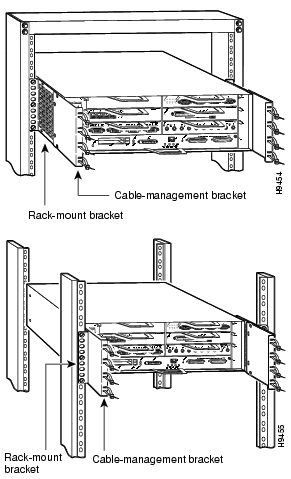
Rack-mounting the RouterThe Cisco 7206 chassis mounts to two rack posts with two rack-mount brackets that attach to either the front or rear sides of the chassis. If you plan to use the cable-management brackets in your rack-mount installation, you must install the cable-management brackets when you install the rack-mount brackets on the chassis.

Warning

Because of the weight of the chassis, do not attempt to rack-mount the router alone. Have another person assist you.
Step 1
Installing brackets on the chassis
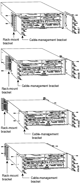
Step 2
Mounting the router in the rack
2
Connecting Cables
Caution To provide proper grounding, always connect the cables to your router first.
Step 1
Cabling 10BASE-T Ethernet (4 or 8 ports)

interfaces
Cabling 10BASE-FL Ethernet
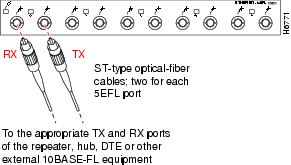
interfaces
Cabling synchronous serial
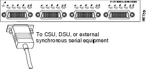
interfaces
Uses DB-60 connectors.
Cabling Token Ring interfaces
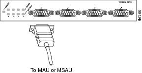
Uses DB-9 connectors.
Cabling Fast Ethernet 100BASE-TX
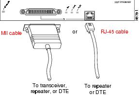
interfaces
Cabling Fast Ethernet 100BASE-FX
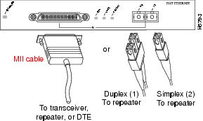
interfaces
SC-type connectors are used with optical fiber.
Cabling multimode FDDI interfaces
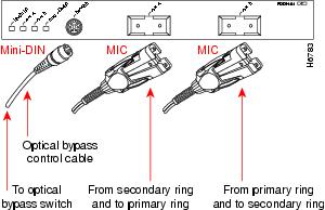
Cabling single-mode FDDI
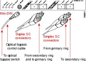
interfaces
Either duplex or simplex SC-type connectors can be used.
The Cisco 7206 supports additional network interfaces such as ATM, ISDN—PRI and BRI, HSSI, and Channelized E1 and T1. Refer to the Cisco Product Catalog for a complete list of network interface types supported by the Cisco 7206.
Step 2
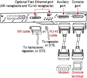
Cabling the I/O Controller
The I/O controller Fast Ethernet port is optional.
Step 3
The Cisco 7206 supports up to two 280W, AC-input or DC-input power supplies. The following illustration shows the AC-input power cable. Refer to the Cisco 7206 Installation and Configuration Guide for DC-input power supply cabling instructions.
Cabling the AC-input Power Supply
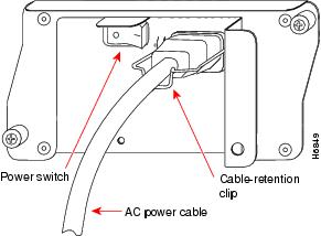
Secure the cable with the cable-retention clip.
3
Starting the router
Step 1
Step 2
I/O Controller LEDs
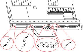
Following are I/O controller LED indications:
•
•
•
•
•
•
•
•
•
Many of the port adapter LEDs will not go on until you have configured their interfaces. If you do not hear the fans operating or you do not get the LED indications shown above after applying power to the router, refer to the chapter "Troubleshooting the Installation" in the Cisco 7206 Installation and Configuration Guide for helpful troubleshooting procedures. If you continue to have startup problems after attempting the troubleshooting procedures, obtain technical assistance.
78-3230-03
 Feedback
Contact Cisco
- Open a Support Case

- (Requires a Cisco Service Contract)