Cisco 7200 VXR Installation and Configuration Guide
Bias-Free Language
The documentation set for this product strives to use bias-free language. For the purposes of this documentation set, bias-free is defined as language that does not imply discrimination based on age, disability, gender, racial identity, ethnic identity, sexual orientation, socioeconomic status, and intersectionality. Exceptions may be present in the documentation due to language that is hardcoded in the user interfaces of the product software, language used based on RFP documentation, or language that is used by a referenced third-party product. Learn more about how Cisco is using Inclusive Language.
- Updated:
- September 23, 2009
Chapter: Installing a Cisco 7200 VXR Router
- Rack-Mounting a Cisco 7200 VXR Router
- Attaching the Chassis Rack-Mount and Cable-Management Brackets
- Installing the Brackets on the Front of the Chassis
- Installing the NPE-G1 and NPE-G2 Cable-Management Brackets on a Front-Mounted Router
- Installing the NPE-G1 and NPE-G2 Optical Cable-Management Bracket
- Installing the Brackets on the Rear of the Chassis
- Installing the NPE-G1 and NPE-G2 Cable-Management Brackets on a Rear-Mounted Router
- Installing the Chassis in the Rack
- Attaching the Chassis Rack-Mount and Cable-Management Brackets
- General Tabletop or Workbench Installation
- Installing the Cable-Management Brackets
- Attaching a Chassis Ground Connection
- Connecting Port Adapter Cables
- Connecting I/O Controller, NPE-G1, or NPE-G2 Cables
Installing a Cisco 7200 VXR Router
This chapter explains how to install a Cisco 7200 VXR router. The chapter contains the following sections:
•![]() Rack-Mounting a Cisco 7200 VXR Router
Rack-Mounting a Cisco 7200 VXR Router
•![]() General Tabletop or Workbench Installation
General Tabletop or Workbench Installation
•![]() Installing the Cable-Management Brackets
Installing the Cable-Management Brackets
•![]() Attaching a Chassis Ground Connection
Attaching a Chassis Ground Connection
•![]() Connecting Port Adapter Cables
Connecting Port Adapter Cables
•![]() Connecting I/O Controller, NPE-G1, or NPE-G2 Cables
Connecting I/O Controller, NPE-G1, or NPE-G2 Cables

Note ![]() For installation and startup procedures for a Cisco 7206VXR as a router shelf in a Cisco AS5800 Universal Access Server, refer to the Cisco AS5800 Universal Access Server publications that shipped with your access server.
For installation and startup procedures for a Cisco 7206VXR as a router shelf in a Cisco AS5800 Universal Access Server, refer to the Cisco AS5800 Universal Access Server publications that shipped with your access server.


Warning ![]() Before you install, operate, or service the system, read the "Site Preparation and Safety" section of the Regulatory Compliance and Safety Information for the Cisco 7200 Series Routers. This guide contains important safety information you should know before working with the system. Statement 200
Before you install, operate, or service the system, read the "Site Preparation and Safety" section of the Regulatory Compliance and Safety Information for the Cisco 7200 Series Routers. This guide contains important safety information you should know before working with the system. Statement 200
A rack-mount and cable-management kit is included in the shipping container. The rack-mount brackets in the kit are for mounting a Cisco 7200 VXR router in standard, 19-inch-wide, four-post equipment racks or two-post equipment racks. The rack-mount brackets are not suitable for use with other racks, such as 23-inch telco racks. The cable-management brackets are designed to relieve the strain on port adapter interface cables that are installed on port adapters in a Cisco 7200 VXR router.
If you are installing an equipment shelf or using mounting hardware other than that supplied with the chassis, review the guidelines in the "Rack-Mounting Guidelines" section on page 2-5 in the chapter "Preparing for Installation," and then proceed to the "General Tabletop or Workbench Installation" section.
If you do not plan to install your Cisco 7200 VXR router in an equipment rack, proceed to the "General Tabletop or Workbench Installation" section.
Rack-Mounting a Cisco 7200 VXR Router
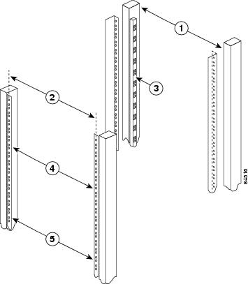
The chassis mounts to two rack posts with brackets that attach to either the front or the rear sides of the chassis. The inside width between the two posts or mounting strips (left and right) must be at least 17.00 inches (43.18 cm).
Note ![]() Rack-mounting procedures for the Cisco 7204VXR and the Cisco 7206VXR are identical. Therefore, the illustrations in this section apply to both Cisco 7200 VXR routers.
Rack-mounting procedures for the Cisco 7204VXR and the Cisco 7206VXR are identical. Therefore, the illustrations in this section apply to both Cisco 7200 VXR routers.
Some equipment racks provide a power strip along the length of one of the mounting strips. Figure 3-1 shows a typical four-post equipment rack with a power strip along one of the back posts. If your rack has this feature, consider the position of the strip when planning fastener points to ensure that you will be able to pull port adapters and other field replaceable units (FRUs) straight out of their respective slots.
The inlet and exhaust ports for cooling air are located on the right and left of the chassis, respectively, so multiple routers can be stacked in a rack with little or no vertical clearance.
Figure 3-1 Typical Four-Post Equipment Rack Posts and Mounting Strips
|
|
Rack posts |
|
Mounting strips |
|
|
18.31 in. (46.48 cm) hole center-to-center |
|
17.00 in. (43.18 cm) minimum |
|
|
110 VAC outlets |
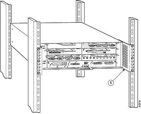
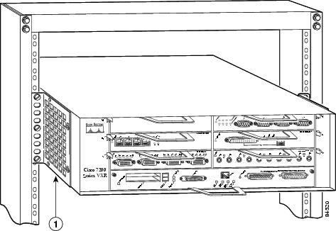
If you want the port adapter end (the front) of the chassis recessed in the rack, install the rack-mount brackets at the front or rear of the chassis in the orientation shown in Figure 3-2. If you want the front of the chassis protruding from the rack, install the rack-mount brackets at the front or rear of the chassis in the orientation shown in Figure 3-3.
Figure 3-2 Installing the Chassis in a Four-Post Rack—Front Installation Shown
|
|
Rack-mount bracket |
Figure 3-3 Installing the Chassis in a Two-Post Rack—Front Installation Shown
|
|
Rack-mount bracket |
If you plan to install the cable-management brackets on a Cisco 7200 VXR router that you are rack-mounting, you must install the cable-management brackets and the rack-mount brackets on the chassis before you install the chassis in the rack.
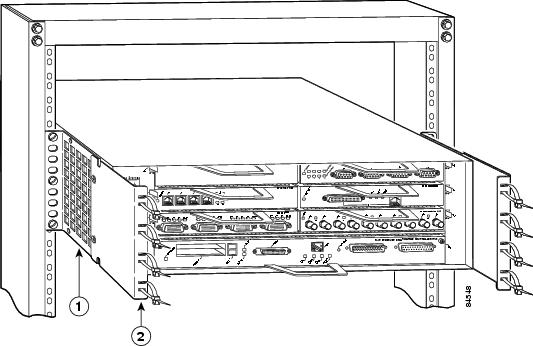
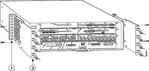
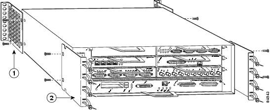
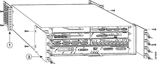
There are two cable-management bracket configurations when you rack-mount a Cisco 7200 VXR router from the front. In the first configuration, the cable-management brackets are installed over the rack-mount brackets, and four screws secure both sets of brackets to the chassis. (See Figure 3-4.) In the second configuration, two screws secure each rack-mount bracket to the chassis, and two additional screws secure each cable-management bracket to a rack-mount bracket. (See Figure 3-5.)
Figure 3-4 Rack-Mounting the Chassis in a Two-Post Rack with Installed
Cable-Management Brackets—Front Installation Shown
|
|
Rack-mount bracket |
|
Cable-management bracket |
Figure 3-5 Rack-Mounting the Chassis in a Four-Post Rack with Installed
Cable-Management Brackets—Front Installation Shown
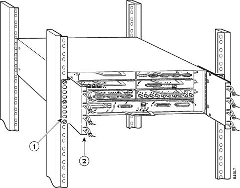
|
|
Rack-mount bracket |
|
Cable-management bracket |
If you are rack-mounting a Cisco 7200 VXR router from the rear, the rack-mount brackets are installed at the rear of the chassis, and the cable-management brackets are installed at the front of the chassis. You must install both sets of brackets before you install the chassis in the rack.
Attaching the Chassis Rack-Mount and Cable-Management Brackets
This section explains how to install the rack-mount and cable-management brackets at the front and the rear of a Cisco 7200 VXR router. Before installing the chassis in the rack, you must install a rack-mount bracket on each side of the front or rear of the chassis. If you are rack-mounting the chassis from the front and you plan to use the cable-management brackets, you must install the cable-management brackets when you install the rack-mount brackets on the chassis.
If you are rack-mounting the chassis from the rear, you may install the rack-mount and cable-management brackets separately; however, both sets of brackets must be installed on the chassis before the chassis is installed in the rack.
The parts and tools required for installing the rack-mount and cable-management brackets are listed in Chapter 2, "Preparing for Installation," the "Tools and Parts Required" section on page 2-1.
Installing the Brackets on the Front of the Chassis
To install the rack-mount and cable-management brackets on a Cisco 7200 VXR router for a front rack-mount configuration, complete the following steps:
Step 1 ![]() Locate the threaded holes in the front sides of the chassis.
Locate the threaded holes in the front sides of the chassis.
Step 2 ![]() If you want the front of the chassis protruding from the rack, align the first rack-mount bracket and the first cable-management bracket to the threaded holes in the right side of the chassis as shown in Figure 3-6.
If you want the front of the chassis protruding from the rack, align the first rack-mount bracket and the first cable-management bracket to the threaded holes in the right side of the chassis as shown in Figure 3-6.
Step 3 ![]() Thread two M4 x 8-mm Phillips flathead screws through both brackets and into the side of the chassis. Use a number 2 Phillips screwdriver to tighten the screws. (See Figure 3-6.)
Thread two M4 x 8-mm Phillips flathead screws through both brackets and into the side of the chassis. Use a number 2 Phillips screwdriver to tighten the screws. (See Figure 3-6.)
Figure 3-6 Installing the Rack-Mount Brackets on the Front of the Chassis so the Front
Protrudes from the Rack
|
|
Rack-mount bracket |
|
Cable-management bracket |
Step 4 ![]() If you want the front of the chassis recessed in the rack, align the first rack-mount bracket to the threaded holes in the right side of the chassis as shown in Figure 3-7.
If you want the front of the chassis recessed in the rack, align the first rack-mount bracket to the threaded holes in the right side of the chassis as shown in Figure 3-7.
Thread two M4 x 8-mm Phillips flathead screws through the bracket into the side of the chassis and use a number 2 Phillips screwdriver to tighten the screws. Then align the first cable-management bracket to the rack-mount bracket and thread two M4 x 8-mm Phillips flathead screws through the two brackets. Use a number 2 Phillips screwdriver to tighten the screws. (See Figure 3-7.)
Figure 3-7 Installing the Rack-Mount Brackets on the Front of the Chassis so the Front
Is Recessed in the Rack

|
|
Rack-mount bracket |
|
Cable-management bracket |
Step 5 ![]() Repeat Step 1 through Step 4 for the other rack-mount bracket and cable-management bracket (if required).
Repeat Step 1 through Step 4 for the other rack-mount bracket and cable-management bracket (if required).
This completes the procedure for installing the rack-mount and cable-management brackets on a Cisco 7200 VXR router for a front rack-mount configuration.
Installing the NPE-G1 and NPE-G2 Cable-Management Brackets on a Front-Mounted Router
You can install Cisco 7200 VXR routers standard cable-management brackets or an optical cable- management bracket on the NPE-G1 or NPE-G2.
•![]() To install the standard cable-management brackets on a Cisco 7200 VXR router with an NPE-G1 or NPE-G2 installed, see the "Installing the Cable-Management Brackets" section.
To install the standard cable-management brackets on a Cisco 7200 VXR router with an NPE-G1 or NPE-G2 installed, see the "Installing the Cable-Management Brackets" section.
•![]() To install the optical cable-management bracket on an NPE-G1 or NPE-G2 in a Cisco 7200 VXR router, see the "Installing the NPE-G1 and NPE-G2 Optical Cable-Management Bracket" section.
To install the optical cable-management bracket on an NPE-G1 or NPE-G2 in a Cisco 7200 VXR router, see the "Installing the NPE-G1 and NPE-G2 Optical Cable-Management Bracket" section.
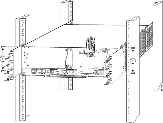
Figure 3-8 Installing the Standard Rear Cable-Management Brackets with an NPE-G1 or NPE-G2—Router Front-Mounted
|
|
Cable-management bracket screws |
If you have an NPE-G1 or NPE-G2 installed, you will want to install standard cable-management brackets on the rear of the router as well as on the front of the router.
Step 1 ![]() If the back of the router protrudes from the rack, place the cable-management brackets against the router as shown in Figure 3-8.
If the back of the router protrudes from the rack, place the cable-management brackets against the router as shown in Figure 3-8.
Step 2 ![]() Insert two screws into each bracket, and tighten them to the router.
Insert two screws into each bracket, and tighten them to the router.
Step 3 ![]() Insert the GBIC cables or RJ-45 cables into the interface ports on the NPE-G1, or the SFP module cables or RJ-45 cables into the interface ports on the NPE-G2.
Insert the GBIC cables or RJ-45 cables into the interface ports on the NPE-G1, or the SFP module cables or RJ-45 cables into the interface ports on the NPE-G2.
Step 4 ![]() Place the cables through the cable-management brackets.
Place the cables through the cable-management brackets.
Installing the NPE-G1 and NPE-G2 Optical Cable-Management Bracket
Figure 3-9 Installing the NPE-G1 and NPE-G2 Optical Cable-Management Bracket
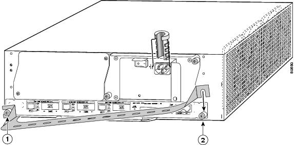
|
|
Left captive installation screw |
|
Right captive installation screw |
Step 1 ![]() Loosen the left and right captive installation screws.
Loosen the left and right captive installation screws.
Step 2 ![]() Hold the cable-management bracket so that it is positioned as shown in Figure 3-9.
Hold the cable-management bracket so that it is positioned as shown in Figure 3-9.
Step 3 ![]() Place the left end of the cable-management bracket over the screw.
Place the left end of the cable-management bracket over the screw.
Step 4 ![]() Rotate the cable-management bracket down, until it slides behind the right captive installation screw.
Rotate the cable-management bracket down, until it slides behind the right captive installation screw.
Step 5 ![]() Tighten both captive installation screws.
Tighten both captive installation screws.
Step 6 ![]() Install the cables, and fasten them to the cable-management bracket with the straps provided.
Install the cables, and fasten them to the cable-management bracket with the straps provided.
Installing the Brackets on the Rear of the Chassis
To install the rack-mount and cable-management brackets on a Cisco 7200 VXR router for a rear rack-mount configuration, complete the following steps:
Step 1 ![]() Locate the threaded holes in the rear sides of the chassis.
Locate the threaded holes in the rear sides of the chassis.
Step 2 ![]() Align the first rack-mount bracket to the threaded holes in the right side of the chassis.
Align the first rack-mount bracket to the threaded holes in the right side of the chassis.
If you want the front of the chassis protruding from the rack, align the rack-mount bracket to the chassis as shown in Figure 3-10. If you want the front of the chassis recessed in the rack, align the rack-mount bracket to the chassis as shown in Figure 3-11.
Figure 3-10 Installing the Rack-Mount Brackets on the Rear of the Chassis so the Front
Protrudes from the Rack
|
|
Rack-mount bracket |
|
Cable-management bracket |
Figure 3-11 Installing the Rack-Mount Brackets on the Rear of the Chassis so the Front
Is Recessed in the Rack
|
|
Rack-mount bracket |
|
Cable-management bracket |
Step 3 ![]() Thread two M4 x 8-mm Phillips flathead screws through the rack-mount bracket and into the side of the chassis. Use a number 2 Phillips screwdriver to tighten the screws.
Thread two M4 x 8-mm Phillips flathead screws through the rack-mount bracket and into the side of the chassis. Use a number 2 Phillips screwdriver to tighten the screws.
Step 4 ![]() Repeat Step 1 through Step 3 for the other rack-mount bracket.
Repeat Step 1 through Step 3 for the other rack-mount bracket.
Step 5 ![]() If you plan to include the cable-management brackets in your rear rack-mount configuration, align the first cable-management bracket to the threaded holes in the front side of the chassis. (See Figure 3-10 and Figure 3-11.)
If you plan to include the cable-management brackets in your rear rack-mount configuration, align the first cable-management bracket to the threaded holes in the front side of the chassis. (See Figure 3-10 and Figure 3-11.)
Step 6 ![]() Thread two M4 x 8-mm Phillips flathead screws through the bracket and into the chassis. Use a number 2 Phillips screwdriver to tighten the screws.
Thread two M4 x 8-mm Phillips flathead screws through the bracket and into the chassis. Use a number 2 Phillips screwdriver to tighten the screws.
Step 7 ![]() Repeat Step 5 and Step 6 for the other cable-management brackets.
Repeat Step 5 and Step 6 for the other cable-management brackets.
Installing the NPE-G1 and NPE-G2 Cable-Management Brackets on a Rear-Mounted Router
Use the instructions in this section to attach the standard cable-management brackets if you have a rear-mounted router.
If you wish to install the NPE-G1 or NPE-G2 optical cable-management bracket, see the "Installing the NPE-G1 and NPE-G2 Optical Cable-Management Bracket" section.
Figure 3-12 Installing the Rear Cable-Management Brackets with the NPE-G1 or NPE-G2—Router Rear-Mounted

|
|
Cable-management bracket screws |
If you have an NPE-G1 or NPE-G2 installed, you will want to install cable-management brackets on the rear of the router as well as on the front of the router.
Step 1 ![]() Align the cable-management brackets with the rack-mount brackets.
Align the cable-management brackets with the rack-mount brackets.
Step 2 ![]() Insert and tighten two screws for each bracket. The screws come with the cable-management brackets.
Insert and tighten two screws for each bracket. The screws come with the cable-management brackets.
This completes the procedure for installing the rack-mount brackets and cable-management brackets on a Cisco 7200 VXR router. Proceed to the "Installing the Chassis in the Rack" section.
Installing the Chassis in the Rack
After installing the brackets on the chassis, you mount the router by securing the rack-mount brackets to two posts or mounting strips in the rack using the six slotted screws provided. Because the brackets support the weight of the entire chassis, be sure to use all six slotted screws to fasten the two rack-mount brackets to the rack posts. Figure 3-2, Figure 3-3, Figure 3-4, and Figure 3-5 show typical installations in 19-inch, four-post and two-post equipment racks.
We recommend that you allow at least 1 or 2 inches (2.54 or 5.08 cm) of vertical clearance between the router and any equipment directly above and below it.
To install the chassis in the rack, complete the following steps:
Step 1 ![]() On the chassis, ensure that all captive screws on the network services engine (NSE) or network processing engine (NPE), the I/O controller, and each power supply are tightened and the port adapter levers are in the locked position.
On the chassis, ensure that all captive screws on the network services engine (NSE) or network processing engine (NPE), the I/O controller, and each power supply are tightened and the port adapter levers are in the locked position.
Step 2 ![]() Make sure that your path to the rack is unobstructed. If the rack is on wheels, ensure that the brakes are engaged or that the rack is otherwise stabilized.
Make sure that your path to the rack is unobstructed. If the rack is on wheels, ensure that the brakes are engaged or that the rack is otherwise stabilized.
Step 3 ![]() Position the chassis so that the front end is closest to you. Lift the chassis and move it to the rack. To prevent injury, avoid sudden twists or moves.
Position the chassis so that the front end is closest to you. Lift the chassis and move it to the rack. To prevent injury, avoid sudden twists or moves.
Step 4 ![]() Slide the chassis into the rack, pushing it back until the brackets (installed at the front or rear of the chassis) meet the mounting strips or posts on both sides of the equipment rack.
Slide the chassis into the rack, pushing it back until the brackets (installed at the front or rear of the chassis) meet the mounting strips or posts on both sides of the equipment rack.
Step 5 ![]() While keeping the brackets flush against the posts or mounting strips, position the router so the holes in the brackets are aligned with those in the mounting strips.
While keeping the brackets flush against the posts or mounting strips, position the router so the holes in the brackets are aligned with those in the mounting strips.
Step 6 ![]() Insert all six 10-32 x 3/8 slotted screws (three on each side) through the brackets and into the mounting strip (use the top and bottom bracket holes, as shown in Figure 3-2, Figure 3-3, Figure 3-4, and Figure 3-5). Using a 1/4-inch flat-blade screwdriver, tighten all the screws.
Insert all six 10-32 x 3/8 slotted screws (three on each side) through the brackets and into the mounting strip (use the top and bottom bracket holes, as shown in Figure 3-2, Figure 3-3, Figure 3-4, and Figure 3-5). Using a 1/4-inch flat-blade screwdriver, tighten all the screws.
This completes the procedure for installing the chassis in the rack. Proceed to the "Connecting Port Adapter Cables" section to continue the installation.
General Tabletop or Workbench Installation
The router should already be in the area where you will install it, and your installation location should already be determined. If not, see Chapter 2, "Preparing for Installation," the "Site Requirement Guidelines" section on page 2-3 and the Site Preparation and Safety Guide.
When installing a Cisco 7200 VXR router on a workbench or tabletop, ensure that the surface is clean and in a safe location and that you have considered the following:
•![]() The router requires at least 3 inches (7.62 cm) of clearance at the inlet and exhaust vents (the right and left sides of the router).
The router requires at least 3 inches (7.62 cm) of clearance at the inlet and exhaust vents (the right and left sides of the router).
•![]() The router should be installed off the floor. (Dust that accumulates on the floor is drawn into the interior of the router by the cooling fans. Excessive dust inside the router can cause overtemperature conditions and component failures.)
The router should be installed off the floor. (Dust that accumulates on the floor is drawn into the interior of the router by the cooling fans. Excessive dust inside the router can cause overtemperature conditions and component failures.)
•![]() There must be approximately 19 inches (48.3 cm) of clearance at the front and rear of the router for installing and replacing router field-replaceable units (FRUs), or accessing network cables or equipment.
There must be approximately 19 inches (48.3 cm) of clearance at the front and rear of the router for installing and replacing router field-replaceable units (FRUs), or accessing network cables or equipment.
•![]() Port adapter and power supply filler panels are installed.
Port adapter and power supply filler panels are installed.
•![]() The router will receive adequate ventilation (it is not being installed in an enclosed cabinet where ventilation is inadequate).
The router will receive adequate ventilation (it is not being installed in an enclosed cabinet where ventilation is inadequate).
•![]() If you plan to install the cable-management brackets on the front of the chassis, you have unpacked and set aside the two cable-management brackets and four M4 x 8-mm Phillips flathead screws.
If you plan to install the cable-management brackets on the front of the chassis, you have unpacked and set aside the two cable-management brackets and four M4 x 8-mm Phillips flathead screws.
•![]() An adequate chassis ground (earth) connection exists for your router chassis.
An adequate chassis ground (earth) connection exists for your router chassis.
Note ![]() We strongly recommend that you provide a chassis ground connection. See the "Attaching a Chassis Ground Connection" section for instructions.
We strongly recommend that you provide a chassis ground connection. See the "Attaching a Chassis Ground Connection" section for instructions.
Following are the steps for installing a Cisco 7200 VXR router on a workbench or tabletop:
Step 1 ![]() Remove any debris and dust from the tabletop or workbench, as well as the surrounding area. Also make sure your path between the router and its new location is unobstructed.
Remove any debris and dust from the tabletop or workbench, as well as the surrounding area. Also make sure your path between the router and its new location is unobstructed.
Step 2 ![]() On the chassis, ensure that all captive screws on the network processing engine or network services engine, the I/O controller, Port Adapter Jacket Card, and each power supply are tightened and the port adapter levers are in the locked position.
On the chassis, ensure that all captive screws on the network processing engine or network services engine, the I/O controller, Port Adapter Jacket Card, and each power supply are tightened and the port adapter levers are in the locked position.
Step 3 ![]() Lift the chassis by placing your hands around the chassis sides and lifting the chassis from underneath. To prevent injury, avoid sudden twists or moves.
Lift the chassis by placing your hands around the chassis sides and lifting the chassis from underneath. To prevent injury, avoid sudden twists or moves.
Step 4 ![]() Place the router on the tabletop or workbench.
Place the router on the tabletop or workbench.
Step 5 ![]() Ensure that there is at least 3 inches (7.62 cm) of clearance at the inlet and exhaust vents of the router and no exhaust air from other equipment will be drawn into the chassis. Also, ensure that there is approximately 19 inches (48.3 cm) of clearance at the front and rear of the chassis.
Ensure that there is at least 3 inches (7.62 cm) of clearance at the inlet and exhaust vents of the router and no exhaust air from other equipment will be drawn into the chassis. Also, ensure that there is approximately 19 inches (48.3 cm) of clearance at the front and rear of the chassis.
This completes the general tabletop or workbench installation.
Installing the Cable-Management Brackets
To install the cable-management brackets on a Cisco 7200 VXR router, complete the following steps:
Step 1 ![]() Locate the threaded holes in the front sides of the chassis.
Locate the threaded holes in the front sides of the chassis.
Step 2 ![]() Align the first cable-management bracket to the threaded holes in the right side of the chassis. (See Figure 3-6.)
Align the first cable-management bracket to the threaded holes in the right side of the chassis. (See Figure 3-6.)
Step 3 ![]() Thread two M4 x 8-mm Phillips flathead screws through the bracket and into the chassis. Use a number 2 Phillips screwdriver to tighten the screws.
Thread two M4 x 8-mm Phillips flathead screws through the bracket and into the chassis. Use a number 2 Phillips screwdriver to tighten the screws.
Step 4 ![]() Install the other cable-management bracket on the left side of the chassis, following the same procedures as in Step 1 and Step 2.
Install the other cable-management bracket on the left side of the chassis, following the same procedures as in Step 1 and Step 2.
Note ![]() If you have an NPE-G1 or NPE-G2, see the "Installing the NPE-G1 and NPE-G2 Cable-Management Brackets on a Front-Mounted Router" section or the "Installing the Brackets on the Rear of the Chassis" section.
If you have an NPE-G1 or NPE-G2, see the "Installing the NPE-G1 and NPE-G2 Cable-Management Brackets on a Front-Mounted Router" section or the "Installing the Brackets on the Rear of the Chassis" section.
This completes the steps for installing the cable-management brackets on a Cisco 7200 VXR router.
Securing the Port Adapter Cables
To secure port adapter interface cables to the cable-management brackets, complete the following steps:
Note ![]() The eight removable tie wraps installed on the cable-management brackets secure port adapter interface cables to the brackets. We recommend that you use the tie wraps that shipped with the cable-management brackets. You can use standard tie wraps; however, you will have to cut and replace them with new tie wraps when you want to release or secure an interface cable to a bracket.
The eight removable tie wraps installed on the cable-management brackets secure port adapter interface cables to the brackets. We recommend that you use the tie wraps that shipped with the cable-management brackets. You can use standard tie wraps; however, you will have to cut and replace them with new tie wraps when you want to release or secure an interface cable to a bracket.
Step 1 ![]() Select a tie wrap and release its locking mechanism.
Select a tie wrap and release its locking mechanism.
Step 2 ![]() Carefully lace the interface cables from a port adapter installed in the chassis between the two ends of the unlocked tie wrap.
Carefully lace the interface cables from a port adapter installed in the chassis between the two ends of the unlocked tie wrap.
Note ![]() Be sure to leave a small service loop in the interface cable before securing it to the cable-management bracket.
Be sure to leave a small service loop in the interface cable before securing it to the cable-management bracket.
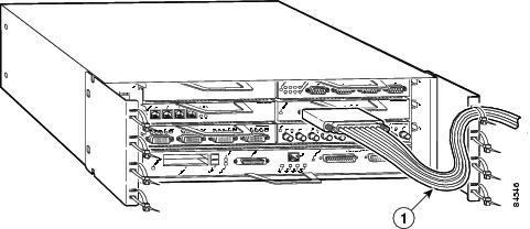
Step 3 ![]() With the interface cables between the ends of the tie wrap and the interface cables service loop in place, tighten the cable tie down around the interface cables until they are secured against the cable-management bracket. (See Figure 3-13.)
With the interface cables between the ends of the tie wrap and the interface cables service loop in place, tighten the cable tie down around the interface cables until they are secured against the cable-management bracket. (See Figure 3-13.)
Figure 3-13 Securing Interface Cables to the Cable-Management Brackets
|
|
Service loop |
Step 4 ![]() Repeat Step 1 through Step 3 for any other port adapter interface cables installed in the router.
Repeat Step 1 through Step 3 for any other port adapter interface cables installed in the router.
This completes the procedure for securing port adapter interface cables to the cable-management brackets. Proceed to the following section "Attaching a Chassis Ground Connection" to continue the installation.
Attaching a Chassis Ground Connection
Before you connect power or turn on power to your router, we strongly recommend that you provide an adequate chassis ground (earth) connection for the router chassis. Chassis grounding receptacles are provided on each Cisco 7200 VXR router chassis. (See Figure 1-4.)
To ensure the chassis grounding connection that you provide is adequate, you will need the following parts and tools:
•![]() One grounding lug—Must have two number-10 screw holes that have a 0.63-inch (16.002-mm) spacing between them, and a wire receptacle large enough to accept a 6-AWG multistrand, copper wire. (See Figure 3-14.) This grounding lug is not available from Cisco Systems; electrical-connector vendors provide this type of grounding lug.
One grounding lug—Must have two number-10 screw holes that have a 0.63-inch (16.002-mm) spacing between them, and a wire receptacle large enough to accept a 6-AWG multistrand, copper wire. (See Figure 3-14.) This grounding lug is not available from Cisco Systems; electrical-connector vendors provide this type of grounding lug.
•![]() Two Phillips machine screws with locking washers—M5 (metric), 0.031-inch (0.8-mm) pitch, 0.315-inch (8-mm) length. These screws are not available from Cisco Systems; they are available from any commercial hardware vendor.
Two Phillips machine screws with locking washers—M5 (metric), 0.031-inch (0.8-mm) pitch, 0.315-inch (8-mm) length. These screws are not available from Cisco Systems; they are available from any commercial hardware vendor.
•![]() One grounding wire—6-AWG, 0.162-inch (4.115-mm) diameter, with approximately 0.108-inch (2.743-mm) insulation, for a total wire diameter of approximately 0.27 inches (6.858 mm). The wire length is dependent on your router location and site environment. This wire is not available from Cisco Systems; it is available from any commercial cable vendor.
One grounding wire—6-AWG, 0.162-inch (4.115-mm) diameter, with approximately 0.108-inch (2.743-mm) insulation, for a total wire diameter of approximately 0.27 inches (6.858 mm). The wire length is dependent on your router location and site environment. This wire is not available from Cisco Systems; it is available from any commercial cable vendor.
•![]() Number 2 Phillips screwdriver
Number 2 Phillips screwdriver
•![]() Crimping tool large enough to accommodate the diameter of the wire receptacle on your grounding lug
Crimping tool large enough to accommodate the diameter of the wire receptacle on your grounding lug
•![]() Wire stripper
Wire stripper
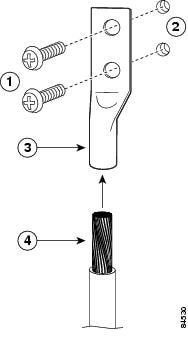
Use the following procedure to attach the grounding lug to the chassis grounding receptacles on your router chassis:
Figure 3-14 Attaching a Grounding Lug to the Chassis Grounding Receptacles
|
|
Screws |
|
Grounding lug |
|
|
Chassis grounding receptacles |
|
Wire |
Step 1 ![]() Locate the chassis grounding receptacles on your router chassis. (See Figure 1-4 in Chapter 1, "Cisco 7206VXR Overview.")
Locate the chassis grounding receptacles on your router chassis. (See Figure 1-4 in Chapter 1, "Cisco 7206VXR Overview.")
Step 2 ![]() Insert the two screws through the holes in the grounding lug. (See Figure 3-14.) Ensure that the grounding lug does not interfere with other router hardware, such as power supplies or the network processing engine or network services engine.
Insert the two screws through the holes in the grounding lug. (See Figure 3-14.) Ensure that the grounding lug does not interfere with other router hardware, such as power supplies or the network processing engine or network services engine.
Step 3 ![]() Use the Phillips screwdriver to carefully tighten the screws until the grounding lug is held firmly to the chassis. Do not overtighten the screws.
Use the Phillips screwdriver to carefully tighten the screws until the grounding lug is held firmly to the chassis. Do not overtighten the screws.
Step 4 ![]() Use the wire stripper to strip one end of the 6-AWG wire approximately 0.75 inches (19.05 mm).
Use the wire stripper to strip one end of the 6-AWG wire approximately 0.75 inches (19.05 mm).
Step 5 ![]() Insert the 6-AWG wire into the wire receptacle on the grounding lug (See Figure 3-14.)
Insert the 6-AWG wire into the wire receptacle on the grounding lug (See Figure 3-14.)
Step 6 ![]() Use the crimping tool to carefully crimp the wire receptacle around the wire; this step is required to ensure a proper mechanical connection.
Use the crimping tool to carefully crimp the wire receptacle around the wire; this step is required to ensure a proper mechanical connection.
Step 7 ![]() Connect the opposite end of the grounding wire to the appropriate grounding point at your site to ensure an adequate chassis ground.
Connect the opposite end of the grounding wire to the appropriate grounding point at your site to ensure an adequate chassis ground.
This completes the procedure for providing a chassis ground connection.
Connecting Port Adapter Cables
The instructions for connecting the cables for each port adapter installed in the Cisco 7200 VXR routers are contained in the respective configuration note for each port adapter. For example, if you are connecting the cables for a 4-port, Ethernet port adapter, refer to the configuration note PA-4E Ethernet 10BaseTPort Adapter Installation and Configuration. The document is available on the Documentation DVD and on Cisco.com.
Instructions for securing port adapter interface cables to the cable-management brackets are contained in the "Installing the Cable-Management Brackets" section.
Connecting I/O Controller, NPE-G1, or NPE-G2 Cables
This section contains connection equipment and pinout information for the Ethernet, Fast Ethernet, Gigabit Ethernet, console, and auxiliary ports that are located on the I/O controller, NPE-G1, or NPE-G2. If you have an NPE-G1 or NPE-G2 installed, you do not need an I/O controller, although an I/O blank panel must be in place if you remove the I/O controller.
The NPE-G1 or NPE-G2 has three Gigabit Ethernet interfaces and six ports; three RJ-45 ports and three GBIC module ports (NPE-G1) or four SFP module ports (NPE-G2). It also has an auxiliary and a console port. See the "RJ-45 Port Cabling and Pinouts" section for information about the RJ-45 console and auxiliary ports. Additionally, the NPE-G2 has a Fast Ethernet Management port.
Note ![]() You can install the C7200-I/O and C7200-I/O-FE I/O controllers in Cisco 7200 VXR routers, including a Cisco 7206VXR router shelf in a Cisco AS5800 Universal Access Server.
You can install the C7200-I/O and C7200-I/O-FE I/O controllers in Cisco 7200 VXR routers, including a Cisco 7206VXR router shelf in a Cisco AS5800 Universal Access Server.
Connecting to Gigabit Ethernet Slots and Ports
The NPE-G2, the NPE-G1, and C7200-I/O-GE+E I/O controller have Gigabit Ethernet slots and ports.
•![]() The NPE-G2 has three Gigabit Ethernet interfaces; four SFP module ports and 3 RJ-45 ports. Any three of the six can be used at the same time.
The NPE-G2 has three Gigabit Ethernet interfaces; four SFP module ports and 3 RJ-45 ports. Any three of the six can be used at the same time.
•![]() The NPE-G1 has three Gigabit Ethernet interfaces; three GBIC module ports and three RJ-45 ports. Any three of the six can be used at the same time.
The NPE-G1 has three Gigabit Ethernet interfaces; three GBIC module ports and three RJ-45 ports. Any three of the six can be used at the same time.
•![]() The C7200-I/O-GE+E I/O controller has one GBIC slot and one Fast Ethernet RJ-45 port.
The C7200-I/O-GE+E I/O controller has one GBIC slot and one Fast Ethernet RJ-45 port.
For further information and specifications, see the Gigabit Interface Converter GBIC Module and Small Form-Factor Pluggable (SFP) GBIC Module Installation Instructions and Specifications
This section contains information on both the GBIC and RJ-45 connections. See the "Gigabit Ethernet GBIC Connections" section or the "Gigabit Ethernet RJ-45 Connections on the NPE-G1 and NPE-G2" section.
Gigabit Ethernet SFP Module Connections
The SFP port is a 1000-Mbps optical interface in the form of an LC-type duplex port that supports
IEEE 802.3z interfaces compliant with the 1000BASEX standard. (See Figure 3-16.)
Warning ![]() Because invisible laser radiation may be emitted from the aperture of the port when no cable is connected, avoid exposure to laser radiation and do not stare into open apertures. Statement 70
Because invisible laser radiation may be emitted from the aperture of the port when no cable is connected, avoid exposure to laser radiation and do not stare into open apertures. Statement 70
Figure 3-15 shows the Class 1 warning label that appears on the Gigabit Ethernet optical ports.
Figure 3-15 Laser Class 1 Warning Label
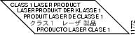
Figure 3-16 shows the duplex LC-type connectors on your multimode or single-mode optical fiber cables. For simplex connectors, two cables are required, one cable for transmit (TX) and a second cable for receive (RX). For duplex connectors, only one cable that has both TX and RX connectors is required. You can use either simplex or duplex connectors to the SFP module ports on the NPE-G2.
Note ![]() We strongly recommend cleaning optical fiber connections before attaching cables to equipment. See the "Fiber-Optic Cleaning Information" section on page 5-10 for information.
We strongly recommend cleaning optical fiber connections before attaching cables to equipment. See the "Fiber-Optic Cleaning Information" section on page 5-10 for information.
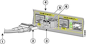
Figure 3-16 SFP Port Connections
|
|
To external 1000BASEX network |
|
Gigabit Ethernet port 0/1 |
|
|
1 duplex connector (TX and RX) |
|
RX (SFP port 0/1) |
|
|
SFP module |
|
TX (SFP port 0/1) |
Table 3-1 provides SFP module specifications.
Table 3-2 provides cabling specifications for the SFP modules that you install in the Gigabit Ethernet SFP ports.
The NPE-G2 supports single Ethernet interfaces based on SFP module technology. The following SFP modules are supported by this line card:
•![]() 100BASE-FX SFP—The SFP-GE-F=,100BASE-FX SFP module is a hot-swappable device that plugs into a Gigabit Ethernet SFP port. It provides full-duplex 100-Mbps connectivity over multimode fiber (MMF) infrastructures. The 100BASE-FX SFP operates on ordinary MMF optical link spans of up to 2 kilometers (km) in length.
100BASE-FX SFP—The SFP-GE-F=,100BASE-FX SFP module is a hot-swappable device that plugs into a Gigabit Ethernet SFP port. It provides full-duplex 100-Mbps connectivity over multimode fiber (MMF) infrastructures. The 100BASE-FX SFP operates on ordinary MMF optical link spans of up to 2 kilometers (km) in length.
•![]() 1000BASE-LX/LH SFP—The SFP-GE-L=, 1000BASE-LX/LH SFP module operates on ordinary single-mode fiber-optic link spans of up to 10,000 meters in length.
1000BASE-LX/LH SFP—The SFP-GE-L=, 1000BASE-LX/LH SFP module operates on ordinary single-mode fiber-optic link spans of up to 10,000 meters in length.
•![]() 1000BASE-SX SFP—The SFP-GE-S=, 1000BASE-SX SFP module operates on ordinary multimode fiber-optic link spans of up to 550 meters in length.
1000BASE-SX SFP—The SFP-GE-S=, 1000BASE-SX SFP module operates on ordinary multimode fiber-optic link spans of up to 550 meters in length.
•![]() 1000BASE-ZX SFP—The SFP-GE-Z=, 1000BASE-ZX SFP module operates on ordinary single mode fiber-optic link spans of up to 70 kilometers in length. Link spans of up to 100 km are possible using premium single-mode fiber or dispersion-shifted single-mode fiber. The SFP module provides an optical link budget of 23 dB—the precise link span length depends on multiple factors such as fiber quality, number of splices, and connectors.
1000BASE-ZX SFP—The SFP-GE-Z=, 1000BASE-ZX SFP module operates on ordinary single mode fiber-optic link spans of up to 70 kilometers in length. Link spans of up to 100 km are possible using premium single-mode fiber or dispersion-shifted single-mode fiber. The SFP module provides an optical link budget of 23 dB—the precise link span length depends on multiple factors such as fiber quality, number of splices, and connectors.
When shorter distances of single-mode fiber are used, it may be necessary to insert an inline optical attenuator in the link to avoid overloading the receiver. A 5-decibel (dB) or 10-dB inline optical attenuator should be inserted between the fiber-optic cable plant and the receiving port on the SFP-GE-Z= at each end of the link whenever the fiber-optic cable span is less than 25 km.
Note ![]() The required line card SFP module is shipped installed in the line card. Cisco sells individual SFP modules separately and you can change the type of Gigabit Ethernet interface supported by this line card by simply changing its SFP module.
The required line card SFP module is shipped installed in the line card. Cisco sells individual SFP modules separately and you can change the type of Gigabit Ethernet interface supported by this line card by simply changing its SFP module.
Note ![]() Optical fiber cables are commercially available; they are not available from Cisco Systems.
Optical fiber cables are commercially available; they are not available from Cisco Systems.
Note ![]() We strongly recommend cleaning optical fiber connections before attaching cables to equipment. See the "Fiber-Optic Cleaning Information" section on page 5-10 for information.
We strongly recommend cleaning optical fiber connections before attaching cables to equipment. See the "Fiber-Optic Cleaning Information" section on page 5-10 for information.
|
|
|
|
|
|
|
|---|---|---|---|---|---|
100BASE-FX |
1270 (min) |
MMF |
62.5 |
500 |
1.24 miles (2 km, 6562 ft) |
1000BASE-LX/LH |
1300 |
MMF1 |
62.5 |
500 |
1804 ft (550 m) |
SMF |
9/10 |
— |
6.2 miles (10 km) |
||
1000BASE-SX |
850 |
MMF |
62.5 |
160 |
722 ft (220 m) |
1000BASE-ZX |
1550 |
SMF |
9/10 |
— |
43.5 miles (70 km) |
1 A mode-conditioning patch cord is required. Using an ordinary patch cord with MMF, 1000BASE-LX/LH SFP modules, and a short link distance (tens of meters) can cause transceiver saturation resulting in an elevated bit error rate (BER). In addition, when using the LX/LH SFP module with 62.5-micron diameter MMF, you must install a mode-conditioning patch cord between the SFP module and the MMF cable on both the transmit and receive ends of the link. The mode-conditioning patch cord is required for link distances greater than 984 ft (300 m). |
Table 3-3 provides SFP module power information.
|
|
|
|
|
||
|---|---|---|---|---|---|
|
|
|
|
|
||
SFP-GE-F= |
|
|
|
|
|
SFP-GE-L= |
-9.5 dBm1 -11.5dBm2 |
-3 dBm3 |
-20 dBm |
-3 dBm |
7.5 dBm4 8.0 dBm5 |
SFP-GE-S= |
-9.5 dBm6 |
-4 dBm6 |
-17 dBm |
0 dBm |
7.5 dBm7 |
SFP-GE-Z= |
0 dBm |
5 dBm |
-23 dBm |
0 dBm |
-24 dBm |
1 For fiber types 9/125 mm SMF. 2 For fiber types 62.5/125 mm MMF and 50/125 mm MMF. 3 For fiber types 9/125 mm SMF, 62.5/125 mm MMF, and 50/125 mm MMF. 4 For fiber types 50/125 mm MMF and 62.5/125 mm MMF. 5 For fiber type 10 mm SMF. 6 For fiber types 50/125 mm, NA = 0.20 fiber and 62.5/125 mm, NA = 0.275 fiber. 7 For fiber types 50/125 mm MMF and 62.5/125 mm MMF. |
Table 3-4 provides NPE-G2 CWDM SFP module configuration information.
Mode-Conditioning Patch Cord Description
A mode-conditioning patch cord can be used with the SFP-GE-L= (SFP module) to allow reliable laser transmission between the single-mode laser source on the SFP module and a multimode optical fiber cable.
When an unconditioned laser source designed for operation on single-mode optical fiber is directly coupled to a multimode optical fiber cable, an effect known as differential mode delay (DMD) might result in a degradation of the modal bandwidth of the optical fiber cable.
This degradation results in a decrease in the link span (the distance between a transmitter and a receiver) that can be supported reliably. The effect of DMD can be overcome by conditioning the launch characteristics of a laser source. A practical means of performing this conditioning is to use a device called a mode-conditioning patch cord.
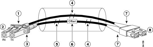
A mode-conditioning patch cord is an optical fiber cable assembly that consists of a pair of optical fibers terminated with connector hardware. Specifically, the mode-conditioning patch cord is composed of a single-mode optical fiber permanently coupled off-center (see Offset in Figure 3-17) to a graded-index multimode optical fiber. Figure 3-17 shows a diagram of the mode-conditioning patch cord assembly.
Figure 3-17 Mode-Conditioning Patch Cord Assembly for an SFP Module
|
|
Gray color identifier |
|
Single-mode bar |
|
|
To Gigabit Ethernet interface |
|
Offset |
|
|
Blue color identifier |
|
Beige color identifier |
|
|
Multimode bar |
|
To cable plant |
The mode-conditioning patch cord assembly is composed of duplex optical fibers, including a single-mode-to-multimode offset launch fiber connected to the transmitter, and a second conventional graded-index multimode optical fiber connected to the receiver. The use of a plug-to-plug patch cord maximizes the power budget of multimode 1000BASELX and 1000BASELH links.
Note ![]() The mode-conditioning patch cord is required to comply with IEEE standards. The IEEE found that link distances could not be met with certain types of fiber-optic cable cores. The solution is to launch light from the laser at a precise offset from the center, which is accomplished by using the mode-conditioning patch cord. At the output of the patch cord, the SFP-GE-L= is compliant with the IEEE 802.3z standard for 1000BASELX.
The mode-conditioning patch cord is required to comply with IEEE standards. The IEEE found that link distances could not be met with certain types of fiber-optic cable cores. The solution is to launch light from the laser at a precise offset from the center, which is accomplished by using the mode-conditioning patch cord. At the output of the patch cord, the SFP-GE-L= is compliant with the IEEE 802.3z standard for 1000BASELX.
Note ![]() We strongly recommend cleaning optical fiber connections before attaching cables to equipment. See the "Fiber-Optic Cleaning Information" section on page 5-10 for information.
We strongly recommend cleaning optical fiber connections before attaching cables to equipment. See the "Fiber-Optic Cleaning Information" section on page 5-10 for information.
Gigabit Ethernet GBIC Connections
The Gigabit Interface Converter (GBIC) port is a 1000-Mbps optical interface in the form of an SC-type duplex port that supports IEEE 802.3z interfaces compliant with the 1000BASEX standard. (See Figure 3-18.)
Note ![]() The GBIC is a separately orderable part and does not ship installed in your I/O controller. You must install the GBIC before you connect the cables to it.
The GBIC is a separately orderable part and does not ship installed in your I/O controller. You must install the GBIC before you connect the cables to it.
Figure 3-18 shows the simplex and duplex SC-type connectors on your multimode or single-mode fiber-optic cables. For simplex connectors, two cables are required, one cable for transmit (TX) and a second cable for receive (RX). For duplex connectors, one cable that has both TX and RX connectors is required. You can use either simplex or duplex connectors for the C7200-I/O-GE+E or the NPE-G1.
Warning ![]() Because invisible laser radiation may be emitted from the aperture of the port when no fiber cable is connected, avoid exposure to laser radiation and do not stare into open apertures. Statement 70
Because invisible laser radiation may be emitted from the aperture of the port when no fiber cable is connected, avoid exposure to laser radiation and do not stare into open apertures. Statement 70
Warning ![]() Class 1 laser product. Statement 1008
Class 1 laser product. Statement 1008
Warning ![]() Class 1 LED product. Statement 1027
Class 1 LED product. Statement 1027
Figure 3-18 GBIC Port Connections

|
|
TX |
|
2 simplex connectors |
|
|
RX |
|
To external 100BASEX network |
|
|
1 duplex connector (TX and RX) |
Table 3-6, Table 3-7, and Table 3-8 describes the available GBIC options and their product numbers.
The NPE-G1 and the I/O controller C7200 I/O-GE+E on the Cisco 7200 VXR routers use Gigabit Ethernet Gigabit Interface Converters (GBICs). The NPE-G1 uses Gigabit Ethernet Coarse Wavelength- Division Multiplexing (CWDM) GBICs as well.
|
|
|
|---|---|
1000BASE-SX |
WS-G5484 |
1000BASE-LX/LH |
WS-G5486 |
1000BASE-ZX |
WS-G5487 |
Note ![]() Fiber-optic cables are commercially available; they are not available from Cisco Systems.
Fiber-optic cables are commercially available; they are not available from Cisco Systems.
GBIC Cabling and Connection Equipment
The GBIC receptacle is a 1000-Mbps optical interface in the form of an SC-type duplex receptacle that supports IEEE 802.3z interfaces compliant with the 1000BASEX standard.
Table 3-8 provides cabling specifications for the GBICs that you install in Gigabit Ethernet slots. Note that all GBIC ports have SC-type connectors. Also, the minimum cable distance for the WS-G5484=
or GBIC-SX and WS-G5486= or GBIC-LX/LH (multimode fiber [MMF] and single-mode fiber [SMF]) is 6.5 feet (2 m), and the minimum link distance for the WS-G5487 or GBIC-ZX-SM is 6.2 miles (10 km) with an 8-dB attenuator installed at each end of the link. Without attenuators, the minimum link distance for the WS-G5487= or GBIC-ZX-SM is 24.9 miles (40 km).
|
|
|
|
|
|
Cable Distance |
|---|---|---|---|---|---|
WS-G5484= |
850 |
MMF1 |
62.5 |
160 |
722 ft (220 m) |
62.5 |
200 |
902 ft (275 m) |
|||
50.0 |
400 |
1640 ft (500 m) |
|||
50.0 |
500 |
1804 ft (550 m) |
|||
WS-G5486= |
1300 |
MMF2 and SMF |
62.5 |
500 |
1804 ft (550 m) |
50.0 |
400 |
1804 ft (550 m) |
|||
50.0 |
500 |
1804 ft (550 m) |
|||
9/10 |
— |
6.2 miles (10 km) |
|||
WS-G5487= |
1550 |
SMF |
9/10 |
— |
43.5 miles (70 km) |
SMF3 |
8 |
— |
62.1 miles (100 km) |
1 Multimode fiber (MMF) only. 2 A mode-conditioning patch cord is required. 3 Dispersion-shifted single-mode fiber-optic cable. |
Table 3-10 provides power requirements and power budget information.
|
|
|
|
|
||
|---|---|---|---|---|---|
WS-G5484 or GBIC-SX |
-9.5 dBm1 |
-4 dBm1 |
-17 dBm |
0 dBm |
7.5 dBm2 |
WS-G5486 or GBIC-LXLH |
-9.5 dBm3 -11.5dBm4 |
-3 dBm5 |
-20 dBm |
-3 dBm |
|
WS-G5487 or GBIC-ZX |
0 dBm |
5.2 dBm |
-24 dBm |
-3 dBm |
-24 dBm |
1 For fiber types 50/125 mm, NA = 0.20 fiber and 62.5/125 mm, NA = 0.275 fiber. 2 For fiber types 50 mm MMF and 62.5 mm MMF. 3 For fiber types 9/125 mm SMF. 4 For fiber types 62.5/125 mm MMF and 50/125 mm MMF. 5 For fiber types 9/125 mm SMF, 62.5/125 mm MMF, and 50/125 mm MMF. 6 For fiber types 50 mm MMF and 62.5 mm MMF. 7 For fiber type 10 mm SMF. |
Note ![]() The 1000BASE-ZX GBIC provides an optical power budget of 21.5 dB. You should measure your cable plant with an optical loss test set to verify that the optical loss of the cable plant (including connectors and splices) is less than or equal to 21.5 dB. The optical loss measurement must be performed with a 1550-nm light source.
The 1000BASE-ZX GBIC provides an optical power budget of 21.5 dB. You should measure your cable plant with an optical loss test set to verify that the optical loss of the cable plant (including connectors and splices) is less than or equal to 21.5 dB. The optical loss measurement must be performed with a 1550-nm light source.
Mode-Conditioning Patch Cord Description
A mode-conditioning patch cord can be used with the WS-G5486= or GBIC-LX/LH= to allow reliable laser transmission between the single-mode laser source on the GBIC and a multimode optical fiber cable.
When an unconditioned laser source designed for operation on single-mode optical fiber is directly coupled to a multimode optical fiber cable, an effect known as differential mode delay (DMD) might result in a degradation of the modal bandwidth of the optical fiber cable.
This degradation results in a decrease in the link span (the distance between a transmitter and a receiver) that can be supported reliably. The effect of DMD can be overcome by conditioning the launch characteristics of a laser source. A practical means of performing this conditioning is to use a device called a mode-conditioning patch cord.
A mode-conditioning patch cord is an optical fiber cable assembly that consists of a pair of optical fibers terminated with connector hardware. Specifically, the mode-conditioning patch cord is composed of a single-mode optical fiber permanently coupled off-center (see Offset in Figure 3-19) to a graded-index multimode optical fiber. Figure 3-19 shows a diagram of the mode-conditioning patch cord assembly.
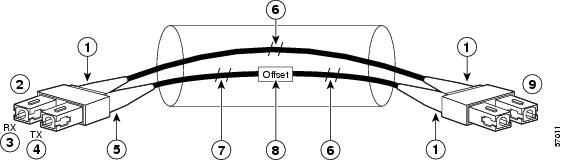
Figure 3-19 GBIC Mode-Conditioning Patch Cord Assembly
|
|
Beige color identifier |
|
Multimode fiber |
|
|
To GE interface |
|
Single-mode fiber |
|
|
RX |
|
Offset |
|
|
TX |
|
To cable plant |
|
|
Blue color identifier |
A mode-conditioning patch cord assembly is composed of duplex optical fibers, including a single-mode-to-multimode offset launch fiber connected to the transmitter, and a second conventional graded-index multimode optical fiber connected to the receiver. The use of a plug-to-plug patch cord maximizes the power budget of multimode 1000BASELX and 1000BASELH links.
Note ![]() The mode-conditioning patch cord is required to comply with IEEE standards. The IEEE found that link distances could not be met with certain types of fiber-optic cable cores. The solution is to launch light from the laser at a precise offset from the center, which is accomplished by using the mode-conditioning patch cord. At the output of the patch cord, the WS-G5486 or GBIC-LX/LH is compliant with the IEEE 802.3z standard for 1000BASELX.
The mode-conditioning patch cord is required to comply with IEEE standards. The IEEE found that link distances could not be met with certain types of fiber-optic cable cores. The solution is to launch light from the laser at a precise offset from the center, which is accomplished by using the mode-conditioning patch cord. At the output of the patch cord, the WS-G5486 or GBIC-LX/LH is compliant with the IEEE 802.3z standard for 1000BASELX.
A mode-conditioning patch cord can be used with the WS-G5486= or GBIC-LX/LH= to allow reliable laser transmission between the single-mode laser source on the GBIC and a multimode fiber-optic cable.
Note ![]() We strongly recommend cleaning optical fiber connections before attaching cables to equipment. See the "Fiber-Optic Cleaning Information" section on page 5-10 for information.
We strongly recommend cleaning optical fiber connections before attaching cables to equipment. See the "Fiber-Optic Cleaning Information" section on page 5-10 for information.
Gigabit Ethernet RJ-45 Connections on the NPE-G1 and NPE-G2
The NPE-G1 and NPE-G2 RJ-45 ports support 10BASET, 100BASETX, and 1000BASET and 1000BASEX protocols and the ports are compliant with IEEE 802.3, IEEE 802.3u, and IEEE 802.1q standards.
The RJ-45 ports support standard straight-through and crossover Category 5 UTP cables with RJ-45 connectors. (See Figure 3-23 and Figure 3-24.) Cisco Systems does not supply Category 5 UTP cables; these cables are available commercially.
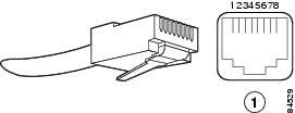
Figure 3-20 shows an RJ-45 port and connector. Table 3-10 lists the pinouts and signals for the RJ-45 port.
|
|
|
|
|---|---|---|
1 |
Tx Data+1 |
Tx A+ |
2 |
Tx Data- |
Tx A- |
3 |
Rx Data+2 |
Rx B+ |
4 |
N/C |
Tx C+ |
5 |
N/C |
Tx C- |
6 |
Rx Data- |
Rx B- |
7 |
N/C |
Rx D+ |
8 |
N/C |
Rx D- |
1 Tx Data = Transmit Data 2 Rx Data = Receive Data |
Note ![]() With reference to the RJ-45 pinouts in Table 3-10, proper common-mode line terminations should be used for the unused Category 5 UTP cable pairs 4/5 and 7/8. Common-mode line termination reduces electromagnetic interference (EMI).
With reference to the RJ-45 pinouts in Table 3-10, proper common-mode line terminations should be used for the unused Category 5 UTP cable pairs 4/5 and 7/8. Common-mode line termination reduces electromagnetic interference (EMI).
Depending on your RJ-45 interface cabling requirements, use the pinouts shown in Figure 3-23 and Figure 3-24 for straight-through and crossover twisted-pair cable connections.
Connecting to the I/O Controller Ethernet and Fast Ethernet Ports
The I/O controller Ethernet and Fast Ethernet ports use two types of ports, RJ-45 ports or MII ports, depending on which I/O controller model you have. The following sections explain the Ethernet and Fast Ethernet connection equipment.
Ethernet and Fast Ethernet RJ-45 Connections
The I/O controller has RJ-45 ports for Ethernet, Fast Ethernet, or autosensing Ethernet and Fast Ethernet connections, depending on your model. The RJ-45 ports support IEEE 802.3 (Ethernet) and IEEE 802.3u (Fast Ethernet) interfaces compliant with 10BASET and 100BASETX specifications.
The RJ-45 port supports standard straight-through and crossover Category 5 unshielded twisted-pair (UTP) cables with RJ-45 connectors. Cisco Systems does not supply Category 5 UTP cables; these cables are available commercially.
Figure 3-20 shows the RJ-45 port and connector. Table 3-11 lists the pinouts and signals for the RJ-45 connector.
Figure 3-20 RJ-45 Port and Connector
|
|
RJ-45 connector and port |
Warning ![]() To avoid electric shock, do not connect safety extra-low voltage (SELV) circuits to telephone-network voltage (TNV) circuits. LAN ports contain SELV circuits, and WAN ports contain TNV circuits. Some LAN and WAN ports both use RJ-45 connectors. Use caution when connecting cables. Statement 1021
To avoid electric shock, do not connect safety extra-low voltage (SELV) circuits to telephone-network voltage (TNV) circuits. LAN ports contain SELV circuits, and WAN ports contain TNV circuits. Some LAN and WAN ports both use RJ-45 connectors. Use caution when connecting cables. Statement 1021
|
|
|
|---|---|
1 |
TxD+1 |
2 |
TxD- |
3 |
RxD+2 |
6 |
RxD- |
1 TxD = Transmit data 2 RxD = Receive data |
Note ![]() With reference to the RJ-45 pinout in Table 3-1, proper common-mode line terminations should be used for the unused Category 5 UTP cable pairs 4/5 and 7/8. Common-mode line termination reduces electromagnetic interference (EMI).
With reference to the RJ-45 pinout in Table 3-1, proper common-mode line terminations should be used for the unused Category 5 UTP cable pairs 4/5 and 7/8. Common-mode line termination reduces electromagnetic interference (EMI).
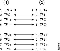
Depending on your RJ-45 interface cabling requirements, use the pinouts shown in Figure 3-21 and Figure 3-22 for Gigabit Ethernet straight-through and crossover twisted-pair cable connections. Use Figure 3-23 for Ethernet/Fast Ethernet straight-through and crossover twisted-pair cable connections.
Figure 3-21 Four Twisted-Pair Straight-Through Cable Pinouts for 10/100/1000 and 1000BASET GBIC Module Ports
|
|
Router |
|
Hub |
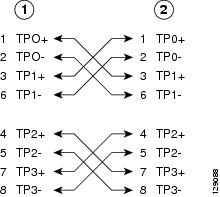
Figure 3-22 Four Twisted-Pair Crossover Cable Pinouts for 10/100/1000 and 1000BASET GBIC Module Ports
|
|
Router |
|
Hub |
Figure 3-23 Ethernet and Fast Ethernet Straight-Through Cable Pinout, Ethernet Port to a Hub or Repeater
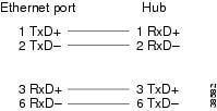
Figure 3-24 Ethernet and Fast Ethernet Crossover Cable Pinout, Ethernet Port to a DTE
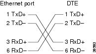
To determine whether a UTP cable is a crossover cable or a straight-through cable, hold the two RJ-45 connectors next to each other so you can see the colored wires inside the ends, as shown in Figure 3-25.
Figure 3-25 Crossover or Straight-Through Cable Identification
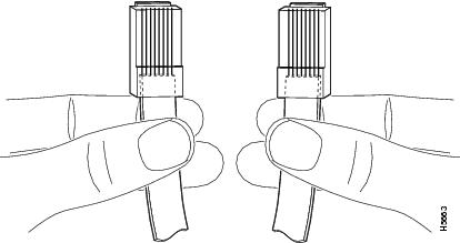
Examine the sequence of colored wires to determine the type of cable, as follows:
•![]() Straight-through—The colored wires are in the same sequence at both ends of the cable.
Straight-through—The colored wires are in the same sequence at both ends of the cable.
•![]() Crossover—The first (far left) colored wire at one end of the cable is the third colored wire at the other end of the cable.
Crossover—The first (far left) colored wire at one end of the cable is the third colored wire at the other end of the cable.
Fast Ethernet MII Connections
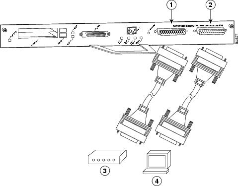
The MII port on the I/O controller is a 40-pin, D-shell-type connector that is configurable for 100 megabits per second (Mbps). The MII port supports IEEE 802.3u interfaces compliant with the 100BASEX and 100BASET standards. The MII connection requires an external transceiver that permits connection to 100BASEFX or 100BASET4 physical media. (See Figure 3-26.)
Figure 3-26 Fast Ethernet Port Connection
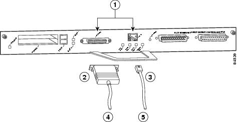
|
|
Optional Fast Ethernet interface (MII port and RJ-45 port) |
|
To transceiver, repeater, or DTE |
|
|
MII connector |
|
To repeater or DTE |
|
|
RJ-45 connector |
Note ![]() To determine if an MII transceiver that is already connected to the MII port on the I/O controller responds to PHY address 0, ensure that the I/O controller Fast Ethernet port is configured as up and the MII port is configured as the media type, and then disconnect the transceiver from the MII port. If the Fast Ethernet port goes down, the transceiver responds to PHY address 0.
To determine if an MII transceiver that is already connected to the MII port on the I/O controller responds to PHY address 0, ensure that the I/O controller Fast Ethernet port is configured as up and the MII port is configured as the media type, and then disconnect the transceiver from the MII port. If the Fast Ethernet port goes down, the transceiver responds to PHY address 0.
The type of media you use between the MII connection and your router, switch, or hub determines the appropriate connectors for the network side of your 100BASET transceiver.
Figure 3-27 shows the pin orientation of the MII port on the I/O controller.
The MII port uses two 56 screw-type locks, called jackscrews, to secure the cable or transceiver to the port. MII cables and transceivers have knurled thumbscrews that you fasten to the jackscrews on the MII port and tighten with your fingers. Use the jackscrews to secure your MII cable to the MII port.
Figure 3-27 MII Port
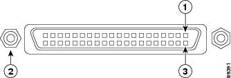
|
|
Pin 1 |
|
Pin 21 |
|
|
Jackscrew |
Table 3-12 lists the pinouts and signals for the I/O controller MII port.
|
|
|
|
|
|
|---|---|---|---|---|
14-17 |
— |
Yes |
— |
Transmit Data (TxD) |
12 |
Yes |
— |
— |
Transmit Clock (Tx_CLK)2 |
11 |
— |
Yes |
— |
Transmit Error (Tx_ER) |
13 |
— |
Yes |
— |
Transmit Enable (Tx_EN) |
3 |
— |
Yes |
— |
MII Data Clock (MDC) |
4-7 |
Yes |
— |
— |
Receive Data (RxD) |
9 |
Yes |
— |
— |
Receive Clock (Rx_CLK)2 |
10 |
Yes |
— |
— |
Receive Error (Rx_ER) |
8 |
Yes |
— |
— |
Receive Data Valid (Rx_DV) |
18 |
Yes |
— |
— |
Collision (COL) |
19 |
Yes |
— |
— |
Carrier Sense (CRS) |
2 |
— |
— |
Yes |
MII Data Input/Output (MDIO) |
22-39 |
— |
— |
— |
Common (ground) |
1, 20, 21, 40 |
— |
— |
— |
+5.0 volts (V) |
1 Any pins not indicated are not used. 2 Tx_CLK and Rx_CLK are provided by the external transceiver. |
Connecting to the Console and Auxiliary Ports
The NPE-G1, NPE-G2, and all I/O controllers have a DCE-mode console port for connecting a console terminal, and a DTE-mode auxiliary port for connecting a modem or other DCE device (such as a CSU/DSU or other router) to your router.
Note ![]() Both the console and the auxiliary ports are asynchronous serial ports; any devices connected to these ports must be capable of asynchronous transmission. (Asynchronous is the most common type of serial device; for example, most modems are asynchronous devices.)
Both the console and the auxiliary ports are asynchronous serial ports; any devices connected to these ports must be capable of asynchronous transmission. (Asynchronous is the most common type of serial device; for example, most modems are asynchronous devices.)
The I/O controller uses two types of physical media for console port and auxiliary port connections. Table 3-13 describes the I/O controller console and auxiliary port media type for each model.
The NPE-G1 and NPE-G2 use RJ-45 media for console port and auxiliary port connections. See Table 3-18 for console port pinout information and Table 3-19 for auxiliary port pinout information.
Before connecting a terminal to the console port, configure the terminal to match the router console port as follows: 9600 baud, 8 data bits, no parity, 2 stop bits (9600 8N2). After you establish normal router operation, you can disconnect the terminal.
DB-25 Port Cabling and Pinouts
The DB-25 ports and connectors conform to the EIA/TIA-232 serial data transfer standard for communications between DTE and DCE equipment. Figure 3-28 shows console and auxiliary port connections for DB-25 physical media.
Figure 3-28 Console and Auxiliary Port DB-25 Connections
|
|
Auxiliary port |
|
Modem |
|
|
Console port |
|
Console terminal |
DB-25 Console Port Signals and Pinouts
Both Data Set Ready (DSR) and Data Carrier Detect (DCD) are supported on the C7200-I/O, C7200-I/O-FE, and C7200-I/O-FE-MII and are active when the system is running. The Request To Send (RTS) signal tracks the state of the Clear To Send (CTS) input. The console port does not support modem control or hardware flow control. Table 3-14 lists the DB-25 console port signals for the C7200-I/O, C7200-I/O-FE, and C7200-I/O-FE-MII. The console port requires a straight-through EIA/TIA-232 cable.
|
|
|
|
|
|---|---|---|---|
1 |
GND |
— |
Ground |
2 |
TxD |
In |
Transmit Data |
3 |
RxD |
Out |
Receive Data |
6 |
DSR |
Out |
Data Set Ready (always on) |
7 |
GND |
— |
Ground |
8 |
DCD |
Out |
Data Carrier Detect (always on) |
1 Any pin not referenced is not connected. |
DB-25 Auxiliary Port Cabling and Pinouts
Table 3-15 lists the DB-25 auxiliary port signals for the C7200-I/O, C7200-I/O-FE, and C7200-I/O-FE-MII I/O controllers. The auxiliary port supports hardware flow control and modem control.
|
|
|
|
|
|---|---|---|---|
2 |
TxD |
Out |
Transmit Data |
3 |
RxD |
In |
Receive Data |
4 |
RTS |
Out |
Request To Send (used for hardware flow control) |
5 |
CTS |
In |
Clear To Send (used for hardware flow control) |
6 |
DSR |
In |
Data Set Ready |
7 |
GND |
— |
Signal Ground |
8 |
DCD |
In |
Data Carrier Detect (used for modem control) |
20 |
DTR |
Out |
Data Terminal Ready (used for modem control only) |
1 Any pin not referenced is not connected. |
Note ![]() When connecting to an auxiliary port on a Cisco 7200 VXR router, the port will not function at baud rates higher than 19.2k. If the baud rate on the connecting device is set higher than 19.2k, either garbled text or nothing will be displayed on the screen.
When connecting to an auxiliary port on a Cisco 7200 VXR router, the port will not function at baud rates higher than 19.2k. If the baud rate on the connecting device is set higher than 19.2k, either garbled text or nothing will be displayed on the screen.
RJ-45 Port Cabling and Pinouts
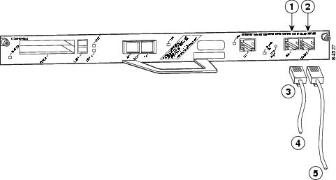
For the NPE-G2, NPE-G1, and the C7200-I/O-GE+E and C7200-I/O-2FE/E I/O controllers, both the console and auxiliary ports use rollover or straight-through cables with RJ-45 connectors. Adapters are available for connection to modems and other external communications equipment. (See Table 3-16.)
Figure 3-29 Console and Auxiliary Port RJ-45 Connector
|
|
Auxiliary port |
|
To modem or DCE |
|
|
Console port |
|
To console terminal |
|
|
RJ-45 connectors |
Both ports are configured as asynchronous serial ports. Figure 3-29 shows the RJ-45 console and auxiliary port connections.
An auxiliary and console port cable and adapter kit is available from Cisco Systems (Product Number ACS-2500ASYN=). Table 3-16 describes the cable and adapter configurations that can be used to connect terminals and modems to the console or the auxiliary asynchronous serial port.
Note ![]() Both the console and the auxiliary ports are asynchronous serial ports; any devices connected to these ports must be capable of asynchronous transmission. (Asynchronous is the most common type of serial device; for example, most modems are asynchronous devices.)
Both the console and the auxiliary ports are asynchronous serial ports; any devices connected to these ports must be capable of asynchronous transmission. (Asynchronous is the most common type of serial device; for example, most modems are asynchronous devices.)
The NPE-G1 and NPE-G2 use RJ-45 media for console port and auxiliary port connections.
Before connecting a terminal to the console port, configure the terminal to match the router console port as follows: 9600 baud, 8 data bits, no parity, 2 stop bits (9600 8N2). After you establish normal router operation, you can disconnect the terminal.
Note ![]() When connecting to an auxiliary port on a Cisco 7200 VXR router, the port will not function at baud rates higher than 19.2k. If the baud rate on the connecting device is set higher than 19.2k, either garbled text or nothing will be displayed on the screen.
When connecting to an auxiliary port on a Cisco 7200 VXR router, the port will not function at baud rates higher than 19.2k. If the baud rate on the connecting device is set higher than 19.2k, either garbled text or nothing will be displayed on the screen.
|
|
|
|
|
|---|---|---|---|
1 |
4 |
5 |
5 |
2 |
20 |
6 |
8 |
3 |
2 |
3 |
3 |
4 |
7 |
7 |
7 |
5 |
7 |
7 |
7 |
6 |
3 |
2 |
2 |
7 |
6 |
20 |
20 |
8 |
5 |
4 |
4 |
1 The female data terminal equipment (FDTE) adapter that is available from Cisco is labeled "Terminal". 2 The MMOD adapter that is available from Cisco is labeled "Modem". |
Refer to Table 3-16 for a list of the pinouts used on the RJ-45-to-DB-25 adapters, used with an RJ-45 cable, to connect terminals and modems to the Cisco7200 VXR routers. The cable you use may be a roll-over cable or a straight-through cable.
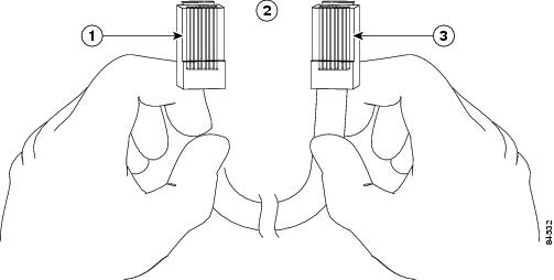
A roll-over cable can be detected by comparing the two modular ends of the cable. Holding the cables in your hand, side-by-side, with the tab at the back, the wire connected to the pin on the outside of the left plug should be the same color as the pin on the outside of the right plug. If your cable was purchased from Cisco, pin 1 will be white on one connector, and pin 8 will be white on the other (a roll-over cable reverses pins 1 and 8, 2 and 7, 3 and 6, and 4 and 5). (See Figure 3-30.)
Figure 3-30 Identifying a Roll-Over Cable
|
|
Pin 1 |
|
Pin 8 |
|
|
Pin 1 and pin 8 should be the same color |
The Cisco 7200 VXR routers ship with a roll-over cable. Connection to a terminal or a modem will require an RJ-45-to-DB-25 adapter, and possibly a DB-25-to-DB9 adapter. Refer to Table 3-17 for the cable and adapter configurations that can be used to connect terminals and modems to the Cisco 7200 VXR routers.
|
|
|
|
|
|---|---|---|---|
Console or auxiliary |
Roll-over |
FDTE1 |
Terminal |
Console or auxiliary |
Straight |
FDCE |
Terminal |
Console or auxiliary |
Roll-over |
MMOD2 |
Modem |
1 The FDTE RJ-45-to-DB-25 adapter is labeled "Terminal". 2 The MMOD RJ-45-to-DB-25 adapter is labeled "Modem". |
RJ-45 Console Port Signals and Pinouts
The NPE-G1, NPE-G2, and the C7200-I/O-2FE/E and C7200-I/O-GE+E I/O controllers do not support Data Carrier Detect (DCD). Table 3-18 lists the RJ-45 console port signals for the NPE-G1, NPE-G2, and the C7200-I/O-2FE/E and C7200-I/O-GE+E I/O controllers.
|
|
|
|
|
|---|---|---|---|
1 |
CTS |
Out |
Clear To Send (tracks RTS) |
2 |
DSR |
Out |
Data Set Ready (always on) |
3 |
RXD |
Out |
Receive Data |
4 |
GND |
— |
Ground |
6 |
TXD |
In |
Transmit Data |
7 |
DTR |
In |
Data Terminal Ready |
8 |
RTS |
In |
Ready To Send |
1 Any pin not referenced is not connected. |
RJ-45 Auxiliary Port Signals and Pinouts for the NPE-G2, NPE-G1 and I/O Controllers
Table 3-19 lists the RJ-45 auxiliary port signals for the C7200-I/O-2FE/E and C7200-I/O-GE+E I/O controllers and NPE-G1, and NPE-G2
|
|
|
|
|
|---|---|---|---|
1 |
RTS |
Out |
Ready To Send |
2 |
DTR |
Out |
Data Terminal Ready |
3 |
TXD |
Out |
Transmit Data |
42 |
RING |
In |
Ring Indication |
5 |
GND |
— |
Signal Ground |
6 |
RXD |
In |
Receive Data |
73 |
DSR/DCD(RLSD) |
In |
Data Set Ready/Data Carrier Detect (Receive Line Signal Detect) |
8 |
CTS |
In |
Clear To Send |
1 Any pin not referenced is not connected. 2 RING is not supported on Cisco-supplied adapters. To use this pin, you must create a customized cable. 3 Pin 7 can be used as a DCD input for connection to a modem. The RJ-45-to-DB-25F adapter maps DCD to this pin when the adapter is used with a straight-through cable. (See Table 3-16.) |
Note ![]() When connecting to an auxiliary port on a Cisco 7200 VXR router, the port will not function at baud rates higher than 19.2k. If the baud rate on the connecting device is set higher than 19.2k, either garbled text or nothing will be displayed on the screen
When connecting to an auxiliary port on a Cisco 7200 VXR router, the port will not function at baud rates higher than 19.2k. If the baud rate on the connecting device is set higher than 19.2k, either garbled text or nothing will be displayed on the screen
Connecting Power
This section provides the procedures for connecting AC-input and DC-input power to your Cisco 7200 VXR router.
Warning ![]() This unit might have more than one power cord. To reduce the risk of electric shock, disconnect the two power supply cords before servicing the unit. Statement 14
This unit might have more than one power cord. To reduce the risk of electric shock, disconnect the two power supply cords before servicing the unit. Statement 14
Note ![]() Detailed instructions for handling and replacing the Cisco 7200 VXR power supplies are contained in the 280-Watt AC Power Supply Replacement Instructions and 280-Watt DC-Input Power Supply Replacement Instructions documents. These documents are available on the Documentation DVD and on Cisco.com.
Detailed instructions for handling and replacing the Cisco 7200 VXR power supplies are contained in the 280-Watt AC Power Supply Replacement Instructions and 280-Watt DC-Input Power Supply Replacement Instructions documents. These documents are available on the Documentation DVD and on Cisco.com.
Warning ![]() The AC power supply has double pole/neutral fusing. Statement 188
The AC power supply has double pole/neutral fusing. Statement 188
Connecting AC-Input Power
Connect a 280W AC-input power supply as follows:
Step 1 ![]() At the rear of the router, check that the power switch is in the off (O) position.
At the rear of the router, check that the power switch is in the off (O) position.
Step 2 ![]() Slide the cable-retention clip up, away from the AC port, and plug in the power cable.
Slide the cable-retention clip up, away from the AC port, and plug in the power cable.
Step 3 ![]() Secure the cable in the power supply AC port by sliding the cable-retention clip down until it fits around the connector. The cable-retention clip provides strain relief for the AC power cable. (See Figure 3-31.)
Secure the cable in the power supply AC port by sliding the cable-retention clip down until it fits around the connector. The cable-retention clip provides strain relief for the AC power cable. (See Figure 3-31.)
Note ![]() For additional AC power cable strain relief, secure the cable to the power supply handle by inserting a nylon cable tie through the hole in the handle and around the cable.
For additional AC power cable strain relief, secure the cable to the power supply handle by inserting a nylon cable tie through the hole in the handle and around the cable.
Step 4 ![]() Plug the AC power supply cable into the AC power source.
Plug the AC power supply cable into the AC power source.
Step 5 ![]() Repeat Step 1 through Step 4 for the second power supply (if present).
Repeat Step 1 through Step 4 for the second power supply (if present).
This completes the procedure for connecting AC-input power.
Figure 3-31 Connecting AC-Input Power

|
|
Power switch |
|
Cable-retention clip |
|
|
AC power cable |
|
Hole for nylon cable tie |
|
|
PWR OK LED |
Connecting DC-Input Power
Two 280W DC-input power supplies are available for the Cisco 7200 VXR routers, a -24V and a -48V power supply. To determine which power supply is in your router, look at the power supply ratings label.
The 24V label located on the power supply next to the cable connector reads 24 - 60V. The 48V label located on the power supply next to the cable connector reads 48 - 60V. For more information on these power supplies see the 280-Watt DC-Input Power Supply Replacement Instructions at http://www.cisco.com/univercd/cc/td/doc/product/core/7200vx/72vxfn/6311dcp.htm.
Connect a 280W DC-input power supply as follows:
Note ![]() The color coding of the DC-input power supply leads depends on the color coding of the DC power source at your site. Typically, green or green/yellow is used for ground. Make certain the lead color coding you choose for the DC-input power supply matches the lead color coding used at the DC power source.
The color coding of the DC-input power supply leads depends on the color coding of the DC power source at your site. Typically, green or green/yellow is used for ground. Make certain the lead color coding you choose for the DC-input power supply matches the lead color coding used at the DC power source.
Warning ![]() Before completing any of the following procedures, ensure that power is removed from the DC circuit. To ensure that all power is OFF, locate the circuit breaker on the panel board that services the DC circuit, switch the circuit breaker to the OFF position, and tape the switch handle of the circuit breaker in the OFF position. Statement 322
Before completing any of the following procedures, ensure that power is removed from the DC circuit. To ensure that all power is OFF, locate the circuit breaker on the panel board that services the DC circuit, switch the circuit breaker to the OFF position, and tape the switch handle of the circuit breaker in the OFF position. Statement 322
Warning ![]() When installing the unit, always make the ground connection first and disconnect it last. Statement 42
When installing the unit, always make the ground connection first and disconnect it last. Statement 42
Step 1 ![]() At the rear of the router, check that the power switch is in the off (O) position.
At the rear of the router, check that the power switch is in the off (O) position.
Step 2 ![]() Ensure that no current is running through the -V and +V leads. To ensure that all power is off, locate the circuit breaker on the panel board that services the DC circuit, switch the circuit breaker to the off position, and tape the switch handle of the circuit breaker in the off position.
Ensure that no current is running through the -V and +V leads. To ensure that all power is off, locate the circuit breaker on the panel board that services the DC circuit, switch the circuit breaker to the off position, and tape the switch handle of the circuit breaker in the off position.
Step 3 ![]() Disconnect the -V and +V leads.
Disconnect the -V and +V leads.
Step 4 ![]() Using a wire stripper, strip approximately 0.55 inch (14 mm) from the -V, +V, and ground leads. (See Figure 3-32.)
Using a wire stripper, strip approximately 0.55 inch (14 mm) from the -V, +V, and ground leads. (See Figure 3-32.)
Figure 3-32 Stripping the DC-Input Leads
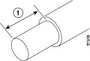
|
|
0.55 in. (14 mm) |
Step 5 ![]() Insert the stripped end of the ground lead all the way into the ground lead receptacle on the DC-input power supply (see Figure 3-33), and tighten the receptacle screw using a 3/16-inch flat-blade screwdriver.
Insert the stripped end of the ground lead all the way into the ground lead receptacle on the DC-input power supply (see Figure 3-33), and tighten the receptacle screw using a 3/16-inch flat-blade screwdriver.
Figure 3-33 Connecting DC-Input Power
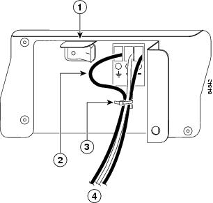
|
|
Power switch |
|
Cable tie |
|
|
Ground lead service loop |
|
DC power leads |
Step 6 ![]() Insert the stripped end of the +V lead all the way into the +V lead receptacle and tighten the receptacle screw using the same 3/16-inch flat-blade screwdriver. Repeat this step for the -V lead.
Insert the stripped end of the +V lead all the way into the +V lead receptacle and tighten the receptacle screw using the same 3/16-inch flat-blade screwdriver. Repeat this step for the -V lead.
Note ![]() Make sure the entire stripped end of each lead is inserted all the way into its receptacle. If any exposed wire at the stripped end of a lead is visible after inserting the lead into its receptacle, remove the lead from the receptacle, use the wire stripper to cut the stripped end of the lead, and repeat Step 4 through Step 6.
Make sure the entire stripped end of each lead is inserted all the way into its receptacle. If any exposed wire at the stripped end of a lead is visible after inserting the lead into its receptacle, remove the lead from the receptacle, use the wire stripper to cut the stripped end of the lead, and repeat Step 4 through Step 6.
Step 7 ![]() After tightening the receptacle screw for the ground, +V, and -V DC-input leads, use a cable tie (see Figure 3-33) to secure the three leads to the power supply faceplate.
After tightening the receptacle screw for the ground, +V, and -V DC-input leads, use a cable tie (see Figure 3-33) to secure the three leads to the power supply faceplate.
Note ![]() When securing the ground, +V, and -V DC-input leads to the power supply faceplate, leave a small service loop in the ground lead to ensure that the ground lead is the last lead to disconnect from the power supply if a great deal of strain is placed on all three leads (see Figure 3-33).
When securing the ground, +V, and -V DC-input leads to the power supply faceplate, leave a small service loop in the ground lead to ensure that the ground lead is the last lead to disconnect from the power supply if a great deal of strain is placed on all three leads (see Figure 3-33).
Step 8 ![]() Switch the circuit breaker to the on position.
Switch the circuit breaker to the on position.
This completes the procedure for connecting DC-input power. Your installation is complete. Proceed to Chapter 4, "Observing System Startup and Performing a Basic Configuration" to start the router and to perform a basic configuration.
 Feedback