Rack-Mount and Cable-Management Kit installation Instructions
Available Languages
Table Of Contents
Rack-Mount and Cable-Management Kit Installation Instructions
Rack-Mount and Cable-Management Kit Overview
Electrical Equipment Guidelines
Rack-Mounting Cisco 7200 Series Routers
Powering Down the Router and Disconnecting Input Power
Installing the Brackets on the Chassis
Installing Brackets on the Front of the Chassis
Installing Brackets on the Rear of the Chassis
Installing the Chassis in the Rack
Reconnecting Input Power and Powering Up the Router
Installing Cable-Management Brackets on Routers in Workbench or Tabletop Configurations
Securing Port Adapter Interface Cables to Cable-Management Brackets
Cisco Product Security Overview
Reporting Security Problems in Cisco Products
Obtaining Technical Assistance
Cisco Technical Support & Documentation Website
Definitions of Service Request Severity
Obtaining Additional Publications and Information
Rack-Mount and Cable-Management Kit Installation Instructions
Product Numbers: ACS-7200-RMK=, CISCO7204=, CISCO7206=, RS7206S=, RS7206VXR=, CISCO7202=, CISCO7204VXR=, CISCO7206VXR=
Document Version History
The document version history is in Table 1.
Introduction
This document explains how to install Cisco 7200 series routers in an equipment rack and how to install the cable-management brackets on the routers using the rack-mount and cable-management kit. The Cisco 7200 series routers consist of the 2-slot Cisco 7202, 4-slot Cisco 7204 and Cisco 7204VXR, and the 6-slot Cisco 7206 and Cisco 7206VXR.
The Cisco 7206VXR and Cisco 7206 can be used as router shelves in a Cisco AS5800 Universal Access Server. References to the Cisco 7200 series routers in this document include the Cisco 7206VXR and Cisco 7206 as router shelves in a Cisco AS5800 Universal Access Server, unless indicated otherwise.
Contents
This document includes the following sections:
•
Rack-Mount and Cable-Management Kit Overview
•
•
•
•
•
Rack-Mount and Cable-Management Kit Overview
The Cisco 7200 series rack-mount and cable-management kit includes rack-mount brackets and cable-management brackets.
The rack-mount brackets are designed for mounting Cisco 7200 series routers in 19-inch, 4-post and telco-type equipment racks. The cable-management brackets are designed to relieve strain on port adapter interface cables that are installed on port adapters in Cisco 7200 series routers.

Note
The cable-management brackets can be installed on Cisco 7200 series routers that are installed on a tabletop or workbench, or in a rack. The rack-mount and cable-management brackets are shipped with Cisco 7200 series routers and are also available as single field-replaceable units (FRUs).
Installation Prerequisites
This section provides a list of parts and tools you need to install the rack-mount and cable-management brackets on Cisco 7200 series routers. This section also includes safety and ESD-prevention guidelines to help you avoid injury to yourself and damage to the equipment.
Tools and Parts Required
You will need the following parts and tools to install the rack-mount and cable-management brackets on your Cisco 7200 series router. If you need additional equipment, contact a service representative for ordering information.
•
•
•
•
•
•
•
•
•
Safety Guidelines
Following are safety guidelines that you should follow when working with any equipment that connects to electrical power or telephone wiring.

Warning
Electrical Equipment Guidelines
Follow these basic guidelines when working with any electrical equipment:
•
•
•
•
•
•
Telephone Wiring Guidelines
Use the following guidelines when working with any equipment that is connected to telephone wiring or to other network cabling:
•
•
•
•
•
•
Chassis Lifting Guidelines
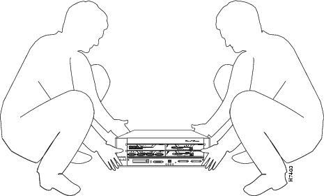
A fully configured Cisco 7200 series router weighs approximately 50 pounds. The chassis is not intended to be moved frequently. Before you install the router, ensure that your site is properly prepared, so you can avoid having to move the chassis later to accommodate power sources and network connections.
Whenever you lift the chassis or any heavy object, follow these guidelines (see Figure 1):
•
•
•
•
•
•
Warning
Figure 1 Lifting the Chassis—Cisco 7204 Shown
Warning
Rack-Mount Considerations
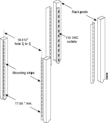
The rack-mounting hardware included with your Cisco 7200 series router is suitable for most 19-inch, 4-post and telco-type equipment racks. Some equipment racks provide a power strip along the length of one of the mounting strips. Figure 2 shows a typical 19-inch, 4-post equipment rack with a power strip along one of the back posts.
If your rack has a power strip, consider the position of the strip when planning fastener points to ensure that you will be able to pull port adapters and other FRUs straight out of their respective slots. If the power strip does impair a rear rack-mount installation, remove the power strip before installing the router in the rack, then replace it after the chassis is installed.
Figure 2 Typical 19-Inch Equipment Rack Posts and Mounting Strips
To use the rack-mounting hardware provided with your Cisco 7200 series router, consider the following guidelines:
•
•
•
•
•
•
•
•
•

Caution
•
•
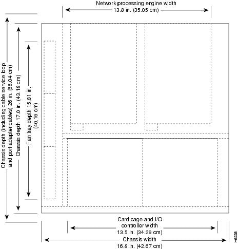
Figure 3 Cisco 7200 Series Router Footprint and Outer Dimensions
Rack-Mounting Cisco 7200 Series Routers
Note
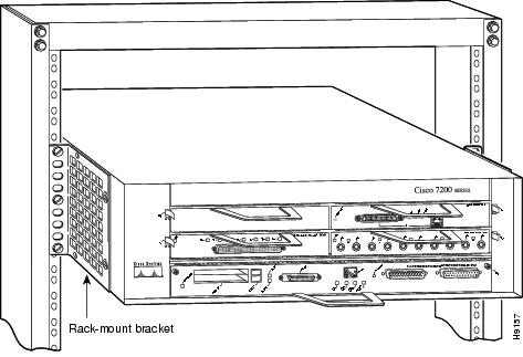
The chassis mounts to two rack posts with two brackets that attach to either the front or the rear sides of the chassis. If you want the port adapter end (the front) of the chassis recessed in the rack, install the rack-mount brackets at the front or rear of the chassis in the orientation shown in Figure 4. If you want the front of the chassis protruding from the rack, install the rack-mount brackets at the front or rear of the chassis in the orientation shown in Figure 5.
Figure 4 Installing the Chassis in a 4-post Rack—Front Installation (Cisco 7204 Shown)
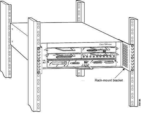
Figure 5 Installing the Chassis in a Telco-Type Rack—Front Installation (Cisco 7204 Shown)
If you plan to install the cable-management brackets on a Cisco 7200 series router that you are rack-mounting, you must install the cable-management brackets and rack-mount brackets on the chassis before you install the chassis in the rack.
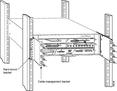
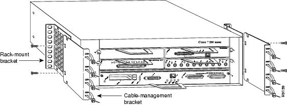
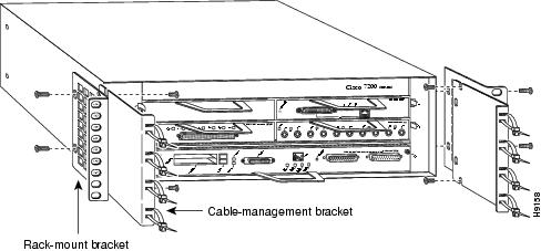
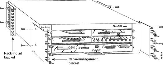
There are two cable-management configurations when you rack-mount a Cisco 7200 series router from the front. In the first configuration, the cable-management brackets are installed over the rack-mount brackets, and four screws secure both sets of brackets to the chassis (see Figure 6). In the second configuration, two screws secure each rack-mount bracket to the chassis, and two additional screws secure each cable-management bracket to a rack-mount bracket (see Figure 7).
Figure 6 Rack-Mounting the Chassis in a Telco-Type Rack With Installed Cable-Management Brackets—Front Installation (Cisco 7204 Shown)
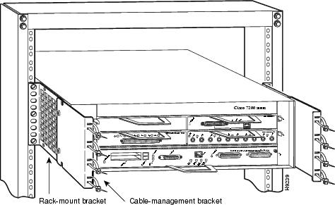
Figure 7 Rack-Mounting the Chassis in a 4-post Rack With Installed Cable-Management Brackets—Front Installation (Cisco 7204 Shown)
If you are rack-mounting a Cisco 7200 series router from the rear, the rack-mount brackets are installed at the rear of the chassis, and the cable-management brackets are installed at the front of the chassis. You must install both sets of brackets before you install the chassis in the rack.
The following sections explain the procedure for rack-mounting the Cisco 7200 series routers:
•
•
•
•
These tasks are described in detail in the following subsections.
Note
Powering Down the Router and Disconnecting Input Power
If your router is already installed on a tabletop or workbench, or in a rack, you must power down the router and disconnect input power before attempting the rack-mount procedure. If your router is already installed in a rack with the original rack-mount brackets (brackets that were shipped before February 1997), you must also remove the original rack-mount brackets from the chassis.
Caution
Powering Down the Router
To power down Cisco 7200 series routers, complete the following steps:
Note
Step 1
Step 2
a.
b.
c.
d.
This completes the procedure for powering down Cisco 7200 series routers.
Disconnecting AC-Input Power
To disconnect AC-input power to Cisco 7200 series routers, complete the following steps:
Step 1
Step 2
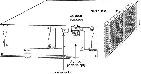
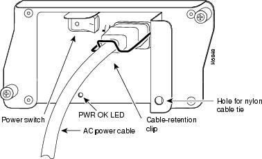
Step 3
Figure 8 Disconnecting Power from a Cisco 7200 Series AC Power Supply
Step 4
This completes the procedure for disconnecting AC-input power to Cisco 7200 series routers.
Disconnecting DC-Input Power
To disconnect DC-input power to Cisco 7200 series routers, complete the following steps:
Warning
Warning
Step 1
Step 2
Note
Step 3
Note
Figure 9 Disconnecting Power from a Cisco 7200 Series DC-Input Power Supply
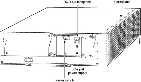
Step 4
This completes the procedure for disconnecting DC-input power to Cisco 7200 series routers.
Installing the Brackets on the Chassis
This section explains how to install the rack-mount and cable-management brackets at the front and the rear of Cisco 7200 series routers. Before installing the chassis in the rack, you must install a rack-mount bracket on each side of the front or rear of the chassis. If you are rack-mounting the chassis from the front and you plan to use the cable-management brackets, you must install the cable-management brackets when you install the rack-mount brackets on the chassis.
If you are rack-mounting the chassis from the rear, you may install the rack-mount and cable-management brackets separately; however, both sets of brackets must be installed on the chassis before the chassis is installed in the rack.
The parts and tools required for installing the rack-mount and cable-management brackets are listed in the "Tools and Parts Required" section.
Warning
Installing Brackets on the Front of the Chassis
To install the rack-mount and cable-management brackets on the chassis for a front rack-mount configuration, complete the following steps:
Step 1
Step 2
Thread two M4 x 8-mm Phillips flathead screws through both brackets and into the side of the chassis. Use a number 2 Phillips screwdriver to tighten the screws. (See Figure 11.)
Figure 10 Installing the Rack-Mount Brackets on the Front of the Chassis so the Front of the Chassis Protrudes from the Rack—Cisco 7204 Shown
Step 3
Thread two M4 x 8-mm Phillips flathead screws through the bracket into the side of the chassis and use a number 2 Phillips screwdriver to tighten the screws. Then align the first cable-management bracket to the rack-mount bracket and thread two M4 x 8-mm Phillips flathead screws through the two brackets. Use a number 2 Phillips screwdriver to tighten the screws. (See Figure 11.)
Figure 11 Installing the Rack-Mount Brackets on the Front of the Chassis so the Front of the Chassis is Recessed in the Rack—Cisco 7204 Shown
Step 4
This completes the procedure for installing the rack-mount and cable-management brackets on the chassis for a front rack-mount configuration.
Installing Brackets on the Rear of the Chassis
To install the rack-mount and cable-management brackets on the chassis for a rear rack-mount configuration, complete the following steps:
Step 1
Step 2
If you want the front of the chassis protruding from the rack, align the rack-mount bracket to the chassis as shown in Figure 12. If you want the front of the chassis recessed in the rack, align the rack-mount bracket to the chassis as shown in Figure 13.
Figure 12 Installing the Rack-Mount Brackets on the Rear of the Chassis so the Front of the Chassis Protrudes from the Rack—Cisco 7204 Shown
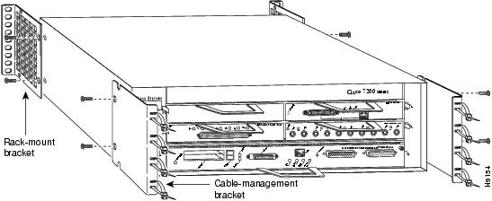
Figure 13 Installing the Rack Mount Brackets on the Rear of the Chassis so the Front of the Chassis is Recessed in the Rack—Cisco 7204 Shown
Step 3
Step 4
Step 5
Step 6
Step 7
This completes the procedure for installing the rack-mount brackets and cable-management brackets on the chassis. Proceed to the section "Installing the Chassis in the Rack.
Warning
Installing the Chassis in the Rack
After installing the brackets on the chassis, mount the router by securing the rack-mount brackets to two posts or mounting strips in the rack using the six slotted screws provided. Because the brackets support the weight of the entire chassis, be sure to use all six slotted screws to fasten the two rack-mount brackets to the rack posts. Figure 4, Figure 5, Figure 6, and Figure 7 show typical installations in a 19-inch 4-post rack and a Telco-type equipment rack.
Warning
Stability hazard. The rack stabilizing mechanism must be in place, or the rack must be bolted to the floor before you slide the unit out for servicing. Failure to stabilize the rack can cause the rack to tip over. Statement 1048
We recommend that you allow at least 1 or 2 inches of vertical clearance between the router and any equipment directly above and below it.
Warning
To install the chassis in the rack, complete the following steps:
Step 1
Step 2
Warning
Warning
Step 3
Step 4
Step 5
Step 6
This completes the procedure for installing the chassis in the rack.
Reconnecting Input Power and Powering Up the Router
The following procedures explain how to reconnect AC-input and DC-input power to Cisco 7200 series routers, power up the router, and verify a successful system boot.
Warning
Reconnecting AC-Input Power
To reconnect AC-input power to Cisco 7200 series routers, complete the following steps:
Step 1
Step 2
Step 3
Figure 14 Connecting AC-Input Power to Cisco 7200 Series Routers
Step 4
Note
Step 5
This completes the steps for reconnecting AC-input power to Cisco 7200 series routers.
Reconnecting DC-Input Power
To reconnect DC-input power to Cisco 7200 series routers, complete the following steps:
Note
Warning
Warning
Step 1
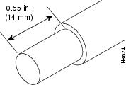
If necessary, use a wire stripper to strip approximately 0.55 inch (14 mm) from the -48V, +48V, and ground leads. (See Figure 15.)
Figure 15 Stripping the DC-Input Leads
Step 2
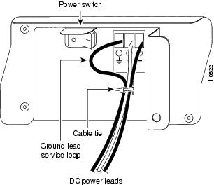
Step 3
Figure 16 Connecting DC-Input Power
Step 4
Note
Step 5
Note
Step 6
Note
This product relies on the building's installation for short-circuit (overcurrent) protection. Ensure that a listed and certified fuse or circuit breaker, 35A minimum 60 VDC, is used on all current-carrying conductors.
Step 7
This completes the steps for reconnecting DC-input power to Cisco 7200 series routers.
Powering Up the Router
To power up Cisco 7200 series routers that have an installed AC-input or DC-input power supply, complete the following steps:
Caution
Step 1
•
•
•
•
•
•
•
•
•
Step 2
Step 3
Step 4
Step 5
Cisco Internetwork Operating System SoftwareIOS (tm) 7200 Software (C7200-J-M), Version 11.1(9) [kpfjrgiu 100]Copyright (c) 1986-1996 by cisco Systems, Inc.Compiled Sun 21-Apr-96 04:10 byThis completes the procedures for connecting input power and powering up the router. This also completes the procedures for rack-mounting Cisco 7200 series routers and attaching cable-management brackets.
Installing Cable-Management Brackets on Routers in Workbench or Tabletop Configurations
This section explains how to install the cable-management brackets on Cisco 7200 series routers in tabletop or workbench installations. Instructions for installing the cable-management brackets on routers in rack-mount installations are in the "Rack-Mounting Cisco 7200 Series Routers" section. The list of tools and parts required to install the cable-management brackets are listed in the "Tools and Parts Required" section.
To install the cable-management brackets on Cisco 7200 series routers, complete the following steps:
Step 1
Step 2
Step 3
Step 4
Step 5
This completes the steps for installing the cable-management brackets on Cisco 7200 series routers in workbench or tabletop configurations.
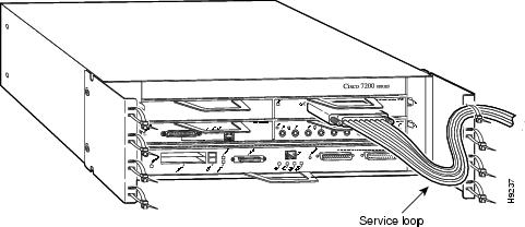
Securing Port Adapter Interface Cables to Cable-Management Brackets
The cable-management brackets are designed to relieve strain on port adapter interface cables that are installed on Cisco 7200 series port adapters. Eight removable tie wraps installed on the cable-management brackets secure port adapter interface cables to the brackets. We recommend that you use the tie wraps that shipped with the cable-management brackets. You can use standard tie wraps; however, you will have to cut and replace them with new tie wraps when you want to release or secure an interface cable to a bracket.
To secure port adapter interface cables to the cable-management brackets, complete the following steps:
Step 1
Step 2
Step 3
Note
Step 4
Figure 17 Securing Interface Cables to the Cable-Management Brackets—Cisco 7204 Shown
Step 5
Step 6
See the "Reconnecting Input Power and Powering Up the Router" section, to reconnect input power and power up Cisco 7200 series routers.
This completes the procedure for securing port adapter interface cables to cable-management brackets on Cisco 7200 series routers.
Related Documentation
See the Cisco 7200 Series Routers Documentation Roadmap for a complete listing of all Cisco 7200 Series Routers documentation.
For Cisco IOS software configuration information and support, refer to the modular configuration and modular command reference publications in the Cisco IOS software configuration documentation set that corresponds to the software release installed on your Cisco hardware.
For hardware installation and maintenance information and software configuration information on the Cisco AS5800 Universal Access Server, refer to the following publications:
•
•
•
Obtaining Documentation
Cisco documentation and additional literature are available on Cisco.com. Cisco also provides several ways to obtain technical assistance and other technical resources. These sections explain how to obtain technical information from Cisco Systems.
Cisco.com
You can access the most current Cisco documentation at this URL:
http://www.cisco.com/techsupport
You can access the Cisco website at this URL:
You can access international Cisco websites at this URL:
http://www.cisco.com/public/countries_languages.shtml
Product Documentation DVD
Cisco documentation and additional literature are available in the Product Documentation DVD package, which may have shipped with your product. The Product Documentation DVD is updated regularly and may be more current than printed documentation.
The Product Documentation DVD is a comprehensive library of technical product documentation on portable media. The DVD enables you to access multiple versions of hardware and software installation, configuration, and command guides for Cisco products and to view technical documentation in HTML. With the DVD, you have access to the same documentation that is found on the Cisco website without being connected to the Internet. Certain products also have .pdf versions of the documentation available.
The Product Documentation DVD is available as a single unit or as a subscription. Registered Cisco.com users (Cisco direct customers) can order a Product Documentation DVD (product number DOC-DOCDVD=) from Cisco Marketplace at this URL:
http://www.cisco.com/go/marketplace/
Ordering Documentation
Beginning June 30, 2005, registered Cisco.com users may order Cisco documentation at the Product Documentation Store in the Cisco Marketplace at this URL:
http://www.cisco.com/go/marketplace/
Nonregistered Cisco.com users can order technical documentation from 8:00 a.m. to 5:00 p.m. (0800 to 1700) PDT by calling 1 866 463-3487 in the United States and Canada, or elsewhere by calling 011 408 519-5055. You can also order documentation by e-mail at tech-doc-store-mkpl@external.cisco.com or by fax at 1 408 519-5001 in the United States and Canada, or elsewhere at 011 408 519-5001.
Documentation Feedback
You can rate and provide feedback about Cisco technical documents by completing the online feedback form that appears with the technical documents on Cisco.com.
You can send comments about Cisco documentation to bug-doc@cisco.com.
You can submit comments by using the response card (if present) behind the front cover of your document or by writing to the following address:
Cisco Systems
Attn: Customer Document Ordering
170 West Tasman Drive
San Jose, CA 95134-9883We appreciate your comments.
Cisco Product Security Overview
Cisco provides a free online Security Vulnerability Policy portal at this URL:
http://www.cisco.com/en/US/products/products_security_vulnerability_policy.html
From this site, you can perform these tasks:
•
•
•
A current list of security advisories and notices for Cisco products is available at this URL:
If you prefer to see advisories and notices as they are updated in real time, you can access a Product Security Incident Response Team Really Simple Syndication (PSIRT RSS) feed from this URL:
http://www.cisco.com/en/US/products/products_psirt_rss_feed.html
Reporting Security Problems in Cisco Products
Cisco is committed to delivering secure products. We test our products internally before we release them, and we strive to correct all vulnerabilities quickly. If you think that you might have identified a vulnerability in a Cisco product, contact PSIRT:
•
An emergency is either a condition in which a system is under active attack or a condition for which a severe and urgent security vulnerability should be reported. All other conditions are considered nonemergencies.
•
In an emergency, you can also reach PSIRT by telephone:
•
•

Tip
Never use a revoked or an expired encryption key. The correct public key to use in your correspondence with PSIRT is the one linked in the Contact Summary section of the Security Vulnerability Policy page at this URL:
http://www.cisco.com/en/US/products/products_security_vulnerability_policy.html
The link on this page has the current PGP key ID in use.
Obtaining Technical Assistance
Cisco Technical Support provides 24-hour-a-day award-winning technical assistance. The Cisco Technical Support & Documentation website on Cisco.com features extensive online support resources. In addition, if you have a valid Cisco service contract, Cisco Technical Assistance Center (TAC) engineers provide telephone support. If you do not have a valid Cisco service contract, contact your reseller.
Cisco Technical Support & Documentation Website
The Cisco Technical Support & Documentation website provides online documents and tools for troubleshooting and resolving technical issues with Cisco products and technologies. The website is available 24 hours a day, at this URL:
http://www.cisco.com/techsupport
Access to all tools on the Cisco Technical Support & Documentation website requires a Cisco.com user ID and password. If you have a valid service contract but do not have a user ID or password, you can register at this URL:
http://tools.cisco.com/RPF/register/register.do
Note
Submitting a Service Request
Using the online TAC Service Request Tool is the fastest way to open S3 and S4 service requests. (S3 and S4 service requests are those in which your network is minimally impaired or for which you require product information.) After you describe your situation, the TAC Service Request Tool provides recommended solutions. If your issue is not resolved using the recommended resources, your service request is assigned to a Cisco engineer. The TAC Service Request Tool is located at this URL:
http://www.cisco.com/techsupport/servicerequest
For S1 or S2 service requests or if you do not have Internet access, contact the Cisco TAC by telephone. (S1 or S2 service requests are those in which your production network is down or severely degraded.) Cisco engineers are assigned immediately to S1 and S2 service requests to help keep your business operations running smoothly.
To open a service request by telephone, use one of the following numbers:
Asia-Pacific: +61 2 8446 7411 (Australia: 1 800 805 227)
EMEA: +32 2 704 55 55
USA: 1 800 553-2447For a complete list of Cisco TAC contacts, go to this URL:
http://www.cisco.com/techsupport/contacts
Definitions of Service Request Severity
To ensure that all service requests are reported in a standard format, Cisco has established severity definitions.
Severity 1 (S1)—Your network is "down," or there is a critical impact to your business operations. You and Cisco will commit all necessary resources around the clock to resolve the situation.
Severity 2 (S2)—Operation of an existing network is severely degraded, or significant aspects of your business operation are negatively affected by inadequate performance of Cisco products. You and Cisco will commit full-time resources during normal business hours to resolve the situation.
Severity 3 (S3)—Operational performance of your network is impaired, but most business operations remain functional. You and Cisco will commit resources during normal business hours to restore service to satisfactory levels.
Severity 4 (S4)—You require information or assistance with Cisco product capabilities, installation, or configuration. There is little or no effect on your business operations.
Obtaining Additional Publications and Information
Information about Cisco products, technologies, and network solutions is available from various online and printed sources.
•
http://www.cisco.com/go/marketplace/
•
•
•
http://www.cisco.com/go/iqmagazine
or view the digital edition at this URL:
http://ciscoiq.texterity.com/ciscoiq/sample/
•
•
http://www.cisco.com/en/US/products/index.html
•
http://www.cisco.com/discuss/networking
•
http://www.cisco.com/en/US/learning/index.html
This document is to be used in conjunction with the documents listed in the "Related Documentation" section.

2005 Cisco Systems, Inc. All rights reserved.


 Feedback
Contact Cisco
- Open a Support Case

- (Requires a Cisco Service Contract)