Input/Output Controller Replacement Instructions
Available Languages
Table Of Contents
Input/Output Controller Replacement Instructions
Input/Output Controller Description
Input/Output Controller C7200-I/O
Input/Output Controller C7200-I/O-GE+E
Input/Output Controller C7200-I/O-2FE/E
Input/Output Controller C7200-I/O-FE
Input/Output Controller C7200-I/O-FE-MII
Software and Hardware Requirements
C7200-I/O-2FE/E I/O Controller
C7200-I/O-FE=, C7200-I/O-MII=, or C7200-I/O= I/O Controllers
Electrical Equipment Guidelines
Electrostatic Discharge Prevention
Removing and Replacing the Input/Output Controller
Copying the Configuration File to a TFTP Server
Powering Down the Router and Disconnecting Input Power
Removing the Input/Output Controller
Replacing an Input/Output Controller
Reconnecting Input Power and Powering Up the Router
Downloading the Saved Configuration from the TFTP Server
Configuring the I/O Controller Interfaces
Configuring Interface Media Type
Configuring Interface Transmission Mode
Performing a Basic Configuration
Using show Commands to Check the Installation
Troubleshooting Using the show interfaces fastethernet Command
Connection Equipment and Port Signaling
Ethernet and Fast Ethernet RJ-45 Connection Equipment
Fast Ethernet MII Connection Equipment
Gigabit Ethernet GBIC Connection Equipment
Console and Auxiliary Port Connection Equipment
DB-25 Port Cabling and Pinouts
RJ-45 Port Cabling and Pinouts
Upgrading the Boot Helper (Boot Loader) Image
Installing and Removing a Flash Memory Card or Flash Disk
Reformatting a Flash Memory Card or Flash Disk
Fiber Optic Cleaning Information
Obtaining Documentation and Submitting a Service Request
Obtaining Additional Publications and Information
Input/Output Controller Replacement Instructions
Product Numbers: C7200-I/O-FE-MII=, C7200-I/O=, C7200-I/O-FE=, C7200-I/O-2FE/E=, C7200-I/O-GE+E=, UBR7200-I/O=, UBR7200-I/O-FE=, UBR7200-I/O-2FE/E=, CISCO7202=, CISCO7204=, CISCO7206=, CISCO7204VXR=, CISCO7206VXR=, CHAS-UBR7246VXR=, CHAS-UBR7246=, CHAS-UBR7223=, RS7206S=, RS7206VXR-SK=, IO-CONTROLR-BLANK=
Document Version History
The document version history is in Table 1.
Introduction
This document explains how to remove and replace the input/output (I/O) controller. This document includes instructions for powering down a router, removing an installed I/O controller, installing a new I/O controller in the router, and verifying the initialization of the installed I/O controller after you power up the router. This document also includes steps for installing and removing a Flash memory card.
Contents
This document contains the following sections:
•
Input/Output Controller Description
•
•
•
•
•
•
•
•
•
Related Documentation
For related documentation, see the following online master indexes for a listing of all documents related to this product:
•
•
http://www.cisco.com/univercd/cc/td/doc/product/core/7206/3419pnc6.htm•
•
•
http://www.cisco.com/univercd/cc/td/doc/product/software/index.htm•
http://www.cisco.com/univercd/cc/td/doc/product/core/7200vx/7200trbl.htm.•
–
http://www.cisco.com/univercd/cc/td/doc/product/cable/cab_rout/cr72hig/index.htm–
http://www.cisco.com/univercd/cc/td/doc/product/cable/cab_rout/cfig_nts/index.htm•
–
–
•
–
–
–
Input/Output Controller Description
The input/output controller shares the system memory functions and the environmental monitoring functions with the network processing engine or network services engine in the Cisco 7200 series routers and Cisco uBR7200 series routers, which include the following:
•

Note
•
This document describes five different models of I/O controllers that are distinguished from one another by their Ethernet interface options. Table 2 lists the I/O controllers by product number and describes their differences. See also the "Software and Hardware Requirements" section.
Table 2 I/O Controller Descriptions1
—
C7200-I/O-GE+E
—
1 Gigabit Ethernet and 1 Ethernet port; equipped with a GBIC port for 1000 megabits per second (Mbps) operation and an RJ-45 port for 10-Mbps operation. (See Figure 1.)
—
C7200-I/O-2FE/E
UBR7200-I/O-2FE/E
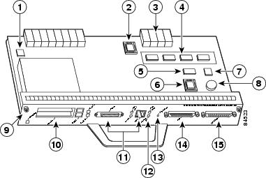
2 autosensing Ethernet/Fast Ethernet ports; equipped with 2 RJ-45 ports for 10/100 Mbps operation. (See Figure 2.)
C7200-I/O-FE3
C7200-I/O-FE3
UBR7200-I/O-FE
1 Fast Ethernet port; equipped with an MII port and an RJ-45 port for use at 100 Mbps full-duplex or half-duplex operation. Only 1 port can be configured for use at a time. (See Figure 3.)
C7200-I/O
C7200-I/O
UBR7200-I/O
Has no Fast Ethernet port. (See Figure 5.)
C7200-I/O-FE-MII4
—
—
1 Fast Ethernet port; equipped with a single MII port. (See Figure 7.)
IO-CONTROLR-
BLANK=Yes
—
I/O Controller Blank panel for use in the I/O controller slot when no I/O controller is in the router.
1 The C7200-I/O-FE-MII I/O controller has reached its end-of-life and is no longer an orderable product as of April 1998. The C7200-I/O-FE I/O controller has reached its end-of-life and is no longer an orderable product as of December 2000.
2 The Cisco uBR7200 series I/O controllers have the boot helper (boot loader) image used by a Cisco uBR7200 series router loaded on the Flash memory SIMMs. The Cisco 7200 series I/O controllers do not.
3 The product number C7200-I/O-FE does not specify MII because both an MII and an RJ-45 port are included.
4 The I/O controller with the product number C7200-I/O-FE-MII has a single MII Fast Ethernet port only.
Note
The I/O controllers consist of the following components and options:
•
•
The console port has full data communications equipment (DCE) functionality, and the auxiliary port has full data terminal equipment (DTE) functionality.
•
Note
•
•
•
•
Figure 1 C7200-I/O-GE+E With GBIC Gigabit Ethernet and RJ-45 Ethernet Ports
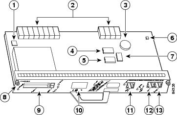
Figure 2 C7200-I/O-2FE/E With Two RJ-45 Ethernet/Fast Ethernet Ports

Your I/O controller with the MII and RJ-45 Fast Ethernet ports (C7200-I/O-FE or UBR7200-I/O-FE) might look like the first illustration in Figure 3 (with NVRAM), or it might look like the second illustration in Figure 4 (with SRAM replacing the NVRAM). There is no functional difference between these two I/O controllers with the Fast Ethernet port.
Figure 3 C7200-I/O-FE With MII and RJ-45 Fast Ethernet Ports (with NVRAM)
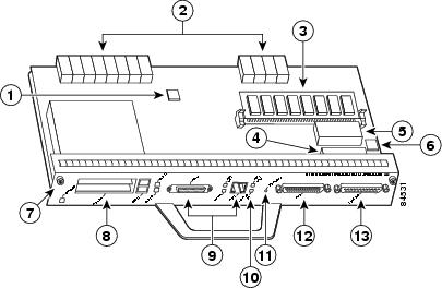
Figure 4 C7200-I/O-FE With MII and RJ-45 Fast Ethernet Ports (with SRAM)
Note
Note
Your I/O controller without the Fast Ethernet port (C7200-I/O or UBR7200-I/O) might look like Figure 5 (with NVRAM), or it might look like Figure 6 (with SRAM replacing the NVRAM). There is no functional difference between these two I/O controllers without the Fast Ethernet port.
Figure 5 C7200-I/O Without Fast Ethernet Port (with NVRAM)
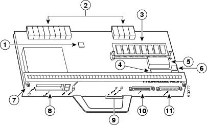
Figure 6 C7200-I/O—Without Fast Ethernet Port (with SRAM)
Note
Figure 7 C7200-I/O-FE-MII With Single MII Fast Ethernet Port
Note
Table 3 lists the I/O controller memory components.
Table 3 Input/Output Controller Memory Components
Boot ROM1
256 KB
1
32-pin DIP-type
C7200-I/O-FE-MII
U20
32-pin DIP-type or 32-pin PLCC-type
C7200-I/O-FE, C7200-I/O
U20 or U4
Flash memory
4 MB
1
Contains the default boot helper (boot loader) image
C7200-I/O-FE-MII
U99
C7200-I/O-FE, C7200-I/O
U99
orU10, U11, U12, and U13 (soldered)2
8 MB
1
C7200-I/O-GE+E, C7200-I/O-2FE/E
U13 and U25 (soldered)2
Flash memory card
20 MB
Up to 2
Contains the default Cisco IOS image
C7200-I/O-FE, C7200-I/O, C7200-I/O-FE-MII
PC Card slot 0 and slot 1
Flash Disk
All models
PC Card disk 0 and disk 1
NVRAM
128 KB
1
Nonvolatile EPROM for the system configuration file
C7200-I/O-FE-MII
U41
C7200-I/O-FE, C7200-I/O
U41
orU14 (soldered)5
C7200-I/O-GE+E, C7200-I/O-2FE/E
U19 (soldered)5
1 The C7200-I/O-GE+E and C7200-I/O-2FE/E do not have a boot ROM component.
2 Some I/O controllers have no Flash SIMM but use a permanently soldered 4-MB or 8-MB Flash chip instead. (For the 4-MB Flash chip, see Figure 3 and Figure 5 for comparison. For the location of the 8-MB Flash, see Figure 1 and Figure 2.)
3 The 48-MB Flash Disk is scheduled for end-of-life in late 2002 and will be replaced by the 64-MB Flash Disk. Existing 48-MB Flash Disks can continue to be used in all I/O controllers.
4 The UBR7200-I/O-FE controller for the Cisco uBR7200 series routers supports only the 48-MB version of the Flash Disk.
5 The NVRAM on some I/O controllers is replaced by a 32-pin nonsocketed SRAM component that is soldered onto the card. The SRAM component is made to act like the NVRAM by the addition of some external components, one of which is a 1-inch (2.54-cm) button-type lithium battery.
Table 4 lists the factory-installed Flash memory card options and their product numbers.
Table 4 Flash Memory Card Options1
8 MB
MEM-I/O-FLC8M
16 MB
MEM-I/O-FLC16M
20 MB
MEM-I/O-FLC20M
1 All Flash memory card options have reached end-of-life and are no longer orderable but are supported in legacy installations. For greater versatility and storage space, we recommend upgrading your routers to the available Flash Disk memory options.
2 Refer to the Cisco AS5800 universal access server documentation listed in the "Related Documentation" section for Cisco AS5800 universal access server Flash memory card options.
Note
Table 5 lists the Flash Disk memory options and their product numbers.
Table 5 Flash Disk Memory Options
32 MB
MEM-I/O-FLD32M1
40 MB
MEM-I/O-FLD40M1
48 MB2
MEM-I/O-FLD48M, MEM-I/O-FLD48M=
64 MB
MEM-I/O-FLD64M, MEM-I/O-FLD64M=
110 MB
MEM-I/O-FLD110M1
128 MB
MEM-I/O-FLD128M, MEM-I/O-FLD128M=
1 These products are no longer orderable but are still supported in legacy systems that originally supported them.
2 The 48-MB Flash Disk is scheduled for end-of-life in late 2002 and will be replaced by the 64 MB Flash Disk. Existing 48 MB Flash Disks can continue to be used in all I/O controllers.
LED Descriptions
The I/O controller faceplate contains LEDs that indicate system and port status; two additional LEDs indicate the status of the Flash Disk or Flash memory cards installed in either PC Card slot. A CPU reset button is located next to the IO power OK LED or next to the auxiliary port on the I/O controller faceplate. The CPU reset button resets the entire system.

Caution
Table 6 lists LEDs common to all models of I/O controllers and describes their functions.
Note
Input/Output Controller C7200-I/O
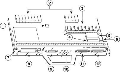
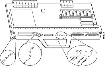
Figure 8 shows the LEDs on the I/O controller model with no Ethernet ports (C7200-I/O or UBR7200-I/O). This I/O controller has no port-specific LEDs. Table 6 describes the LEDs on this I/O controller.
Figure 8 C7200-I/O LEDs and CPU Reset Button

Input/Output Controller C7200-I/O-GE+E
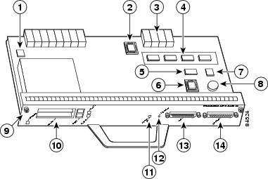
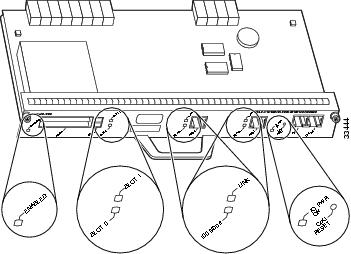
Figure 9 shows the LEDs on the I/O controller with the Gigabit Ethernet port and the Ethernet port (C7200-I/O-GE+E, and Table 7 lists the LEDs specific to this I/O controller model. Table 6 lists the LEDs on this controller that are common to all controllers.
Figure 9 C7200-I/O-GE+E LEDs and CPU Reset Button
Input/Output Controller C7200-I/O-2FE/E
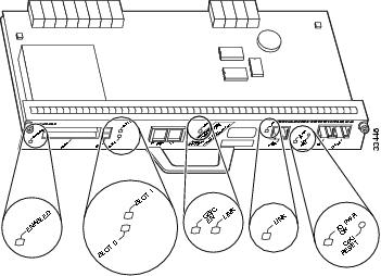
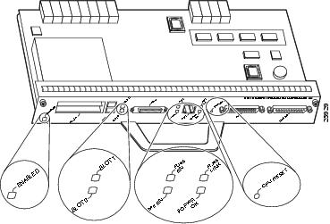
Figure 10 shows the LEDs on the I/O controller with the two autosensing 10/100-Mbps RJ-45 ports (C7200-I/O-2FE/E or UBR7200-I/O-2FE/E), and Table 8 lists the LEDs specific to this I/O controller model. Table 6 lists the LEDs on this controller that are common to all controllers.
Figure 10 C7200-I/O-2FE/E LEDs and CPU Reset Button
Caution
Input/Output Controller C7200-I/O-FE
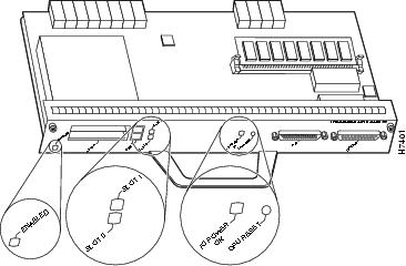
Figure 11 shows the LEDs on the I/O controller with the Fast Ethernet port that is equipped with an MII port and Figure 12 shows an I/O controller with an RJ-45 port (C7200-I/O-FE). Table 9 lists the LEDs specific to this I/O controller model. Table 6 lists the LEDs on this controller that are common to all controllers.
Note
Figure 11 C7200-I/O-FE LEDs and CPU Reset Button

Figure 12 C7200-I/O-FE LEDs and CPU Reset Button (RJ-45)
Note
Input/Output Controller C7200-I/O-FE-MII
Figure 13 shows the LEDs on the I/O controller with the Fast Ethernet port equipped with a single MII port (C7200-I/O-FE-MII), and Table 10 lists the LEDs specific to this I/O controller model. Table 6 lists the LEDs on this controller that are common to all controllers.
Note
Figure 13 C7200-I/O-FE-MII LEDs and CPU Reset Button
Installation Prerequisites
This section provides a list of parts and tools you need to remove and replace the I/O controller in Cisco 7200 series routers or Cisco uBR7200 series routers. This section also includes safety and ESD-prevention guidelines to help you avoid injury to yourself and damage to the equipment.
List of Parts and Tools
You need the following parts and tools to remove and replace the I/O controller. If you need additional equipment, contact a service representative for ordering information:
•
•
•
•
•
•
•
•
Software and Hardware Requirements
Table 11 lists the recommended minimum Cisco IOS software release (and boot helper [boot loader] image) to use with the I/O controller in supported router platforms.
Table 11 I/O Controller Minimum Software and Boot Helper (Boot Loader) Image Requirements
Cisco 7204VXR and Cisco 7206VXR
Cisco IOS Release 12.0(2)XE2
Cisco IOS Release 12.0(3)T or later releases
Cisco IOS Release 12.2(4)B or later releases
Cisco IOS Release 12.1(3a)E or later releases
Cisco IOS Release 12.1(5)T or later releases
Cisco IOS Release 12.0(14)S or later releases
Cisco IOS Release 12.2(4)B or later releases
Note
Cisco IOS Release 12.1(3a)E or later releases
Cisco IOS Release 12.1(5)T or later releases
Cisco IOS Release 12.0(14)S or later releases
Cisco IOS Release 12.2(4)B or later releases
Note
Cisco 7200
Cisco IOS Release 11.1(17)CA or later releases
Cisco IOS Release 11.2(12)P or later releases
Cisco IOS Release 11.3(2)T or later releases
Cisco IOS Release 11.3(2)AA or later releases
Cisco IOS Release 12.2(4)B or later releases
Not supported
Not supported
Cisco 7204
Cisco IOS Release 11.1(17)CA or later releases
Cisco IOS Release 11.2(12)P or later releases
Cisco IOS Release 11.3(2)T or later releases
Cisco IOS Release 11.3(2)AA or later releases
Not supported
Not supported
Cisco 72021
Cisco IOS Release 11.1(19)CC1 or later releases
Cisco IOS Release 11.3(4)AA or later releases
Not supported
Not supported
Cisco 7206 router shelf
Cisco IOS Release 11.3(2)AA or later releases
Not supported
Not supported
Cisco 7206VXR router shelf
Cisco IOS Release 12.0(4)XJ or later releases
Not supported
Not supported
Cisco uBR7246VXR
Cisco IOS Release 12.0(6)SC or later releases5
Cisco IOS Release 12.1(3a)EC1 or later releases
Cisco IOS Release 12.2(4)BC1 or later releases
Cisco IOS Release 12.1(10)EC or later releases
Cisco IOS Release 12.2(4)BC1 or later releases
Note
Not supported
Cisco uBR7246 and Cisco uBR7223
Cisco IOS Release 11.3(6)NA or later releases5
Cisco IOS Release 12.0(6)SC or later releases
Cisco IOS Release 12.1(3a)EC1 or later releases
Cisco IOS Release 12.2(4)BC1 or later releases
Not supported
Not supported
1 You can install an I/O controller with or without a Fast Ethernet port in a Cisco 7202; however, when you install an I/O controller with a Fast Ethernet port, the Cisco 7202 system software automatically disables the port.
2 The Cisco 7206 and Cisco 7206VXR can be used as router shelves in a Cisco AS5800 universal access server. For information about the Cisco AS5800 universal access server, refer to the Cisco AS5800 universal access server documentation listed in the "Related Documentation" section.
3 If you need to order a spare I/O controller for a Cisco uBR7200 series router, use the Cisco uBR7200 series product number followed by an equal sign (=). These I/O controllers have the Cisco uBR7200 series boot helper (boot loader) image loaded on the Flash SIMMs. (For Cisco uBR7200 series product numbers, see Table 2.)
4 Initial shipments of the Cisco uBR7246 chassis that were equipped with a Fast Ethernet I/O controller might have an I/O controller with the single MII port installed. These I/O controllers are fully compatible with the router. If you need to order a spare I/O controller, use the product numbers described in the previous footnote.
5 To support the UBR7200-I/O-FE, the Cisco uBR7200 series routers can use any previous boot image that supports a supported version of Cisco IOS software. However, we recommend using the Cisco IOS Release 12.0(15)SC [ubr7200-boot-mz.12.0-15.SC] boot image for maximum feature support.
6 The Cisco IOS Release 12.1(10)EC or later Cisco IOS Release 12.1 EC boot image must be used only on a Cisco uBR7246VXR using the UBR7200-I/O-2FE/E controller. This boot helper image must not be used for any Cisco uBR7200 series router using the UBR7200-I/O-FE controller.
Depending on the I/O controller model you have, the hardware requirements in the following sections apply.
C7200-I/O-2FE/E I/O Controller
The C7200-I/O-2FE/E I/O controller operates only in the Cisco 7204VXR and Cisco 7206VXR routers, and in the Cisco uBR7246VXR universal broadband router.
•
•
•
Note
To check for the correct NPE-225 version in software, use the show c7200 command. Under CPU EEPROM, look for Hardware Revision 1.3 or higher.
Note
•
•
•
Additionally, the following error message appears in the system banner at bootup:
PA-3-NOTSUPPORTED: PA in slot0 (Dual FastEthernet/Ethernet (with GBIC/RJ45) I/O
Card) is not supported on this chassis or npe cpu card
Note
%c7200-3-IONOTSUPPORTEDBYLOADER: I/O controller (type 539) is not supported by this boot loader. The I/O controller network interfaces will be unavailable.
C7200-I/O-GE+E I/O Controller
The C7200-I/O-GE+E I/O controller operates only in the Cisco 7204VXR and Cisco 7206VXR routers
•
•
The Cisco C7200-I/O-GE+E I/O controller operates with the following NPEs and network services engine (NSE) only on the Cisco 7204VXR and Cisco 7206VXR routers: NPE-300, NPE-400, NPE-G1, and NSE-1.
Note
•
Additionally, the following error message appears in the system banner at bootup:
PA-3-NOTSUPPORTED: PA in slot0 (GigabitEthernet/Ethernet (with GBIC/RJ45) I/O Card) is
not supported on this chassis or npe cpu card
Note
%c7200-3-IONOTSUPPORTEDBYLOADER: I/O controller (type 539) is not supported by this boot loader. The I/O controller network interfaces will be unavailable.
C7200-I/O-FE=, C7200-I/O-MII=, or C7200-I/O= I/O Controllers
You can install the C7200-I/O-FE, C7200-I/O-MII, or C7200-I/O in all Cisco 7200 series routers (including the Cisco 7206 and Cisco 7206VXR as router shelves in a Cisco AS5800 universal access server); however, when you install an I/O controller with a Fast Ethernet port in a Cisco 7202, the system software automatically disables the port.
•
•
%C7200-3-UNSUPPORTED: FE in slot0 is not supported on C7202 chassisIf the above message appears, the Fast Ethernet port on the I/O controller is automatically disabled. If the above message does not appear, your Cisco 7202 has an installed I/O controller without the Fast Ethernet port.
•
•
•
•
Note
Safety Guidelines
Following are safety guidelines that you should follow when working with any equipment that connects to electrical power or telephone wiring.
Safety Warnings
Electrical Equipment Guidelines
Follow these basic guidelines when working with any electrical equipment:
•
•
•
•
•
•
Telephone Wiring Guidelines
Use the following guidelines when working with any equipment that is connected to telephone wiring or to other network cabling:
•
•
•
•
Electrostatic Discharge Prevention
Electrostatic discharge (ESD) damages equipment and impairs electrical circuitry. ESD occurs when printed circuit boards are improperly handled and results in complete or intermittent failures.
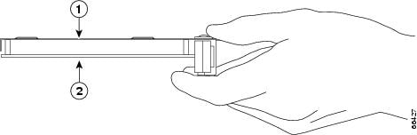
The network processing engine or network services engine, I/O controller, port adapters, and Cisco uBR7200 series cable modem cards consist of a printed circuit board that is fixed in a metal carrier. Electromagnetic interference (EMI) shielding, connectors, and a handle are integral components of the carrier. Handle the network processing engine or network services engine, I/O controller, port adapters, and Cisco uBR7200 series cable modem cards by their carrier edges and handles; never touch the printed circuit board or connector pins.
Figure 14 shows the location of a printed circuit board in a network processing engine, network services engine, I/O controller, or Cisco uBR7200 series cable modem card metal carrier. Do not touch the printed circuit board when handling any of the components.
Figure 14 Handling the Network Processing Engine or Network Services Engine, the I/O Controller, and the Cisco uBR7200 Series Cable Modem Cards—Side View
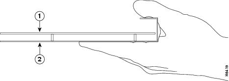
Figure 15 shows the location of a printed circuit board in a port adapter metal carrier. Do not touch the printed circuit board when handling a port adapter.
Figure 15 Handling a Port Adapter—Side View
Although the metal carrier helps to protect the printed circuit boards from ESD, wear a preventive antistatic strap whenever handling the network processing engine or network services engine, I/O controller, port adapters, or Cisco uBR7200 series cable interface line cards. Ensure that the strap makes good skin contact, and connect the strap's clip to an unpainted chassis surface to safely channel unwanted ESD voltages to ground.
If no wrist strap is available, ground yourself by touching the metal part of the chassis.
Caution
Following are guidelines for preventing ESD damage:
•
•
•
Caution
Removing and Replacing the Input/Output Controller

Warning
Statement 1030
To see translations of the warnings that appear in this publication, refer to the Regulatory Compliance and Safety Information document that accompanied this device.
The following sections explain how to remove and replace an I/O controller in Cisco 7200 series routers or Cisco uBR7200 series routers:
•
•
•
•
•
•
Note
The procedures for removing and replacing an I/O controller in Cisco uBR7200 series routers are the same as for the platforms mentioned above; however, to show differences in the chassis and I/O controller location, separate illustrations are provided for Cisco uBR7200 series routers.
Copying the Configuration File to a TFTP Server
Before you replace the I/O controller, be sure to copy the router running configuration to a TFTP file server so that you can retrieve it later; otherwise, you will have to reenter your configuration manually.
Before copying the router configuration file to a TFTP file server, check the following items:
•
•
•
•
To copy the router's configuration file to a remote host, complete the following steps:
Step 1
Step 2
Step 3
Note
Step 4
Router# copy startup-config tftpRemote host []?Step 5
Router# copy startup-config tftpRemote host []? servernameTranslating "servername"...domain server (10.1.1.1) [OK]Step 6
Name of configuration file to write [Router-confg]?Write file Router-confg on host 10.1.1.1? [confirm]Writing Router-confg.....Step 7
Write file Router-confg on host 10.1.1.1? [confirm]Writing Router-confg: !!!! [ok]While the router copies the configuration to the remote host, it displays a series of exclamation points (!!!) or periods (. . .). The series of exclamation points (!!!!) and [ok] indicate that the operation is successful. A display of periods (. . .) and [timed out] or [failed] indicates a failure, which would probably be because of a network fault or the lack of a writable, readable file on the remote file server.
Step 8
•
•
Writing Router-confg .....Step 9
This completes the procedure for copying the configuration file to a TFTP server. Proceed to the next section, "Powering Down the Router and Disconnecting Input Power."
Powering Down the Router and Disconnecting Input Power
Complete the steps in the following sections to power down the router and disconnect input power.
Warning
To see translations of the warnings that appear in this publication, refer to the Regulatory Compliance and Safety Information document that accompanied this device.
Powering Down the Router
To power down a Cisco 7200 series router or Cisco uBR7200 series router, complete the following steps:
Step 1
Step 2
•
•
•
•
•
Caution
Caution
This completes the procedure for powering down a Cisco 7200 series router or Cisco uBR7200 series router.
Disconnecting AC-Input Power
To disconnect AC-input power from a Cisco 7200 series router or Cisco uBR7200 series router, complete the following steps:
Step 1
Step 2
•
•
Step 3
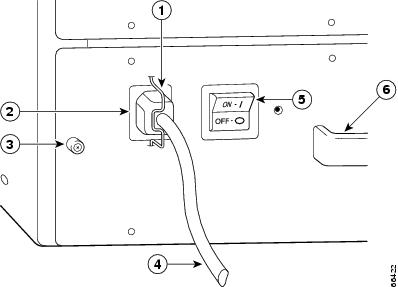
Figure 16 Disconnecting Power from a Cisco 7200 Series AC-Input Power Supply

Figure 17 Disconnecting Power from a Cisco uBR7200 Series AC-Input Power Supply (Cisco uBR7246 Shown)
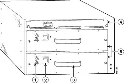
AC-input power receptacle
Network processing engine
Power switch
AC-input power supply
Handle
Step 4
This completes the procedure for disconnecting AC-input power from a Cisco 7200 series router or Cisco uBR7200 series router.
Disconnecting DC-Input Power
Before completing any of the following steps, and to prevent short-circuit or shock hazards, ensure that power is removed from the DC circuit. To ensure that all power is off, locate the circuit breaker on the panel board that services the DC circuit, switch the circuit breaker to the off position, and tape the switch handle of the circuit breaker in the off position.
Warning
Statement 42
To see translations of the warnings that appear in this publication, refer to the Regulatory Compliance and Safety Information document that accompanied this device.
To disconnect DC-input power from a Cisco 7200 series router or Cisco uBR7200 series router, complete the following steps:
Step 1
Step 2
•
Note
•
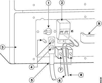
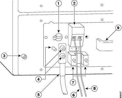
Figure 18 Removing the Strain-Relief Cover from a Cisco uBR7200 Series DC-Input Power Supply
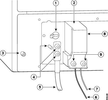
Power switch
-V lead
Power receptacle
+V lead
Captive installation screw
Strain-relief cover
M5 grounding receptacles
M4 nuts
M5 grounding lug
Step 3
•
•
Note
Figure 19 Disconnecting Power from a Cisco 7200 Series DC-Input Power Supply
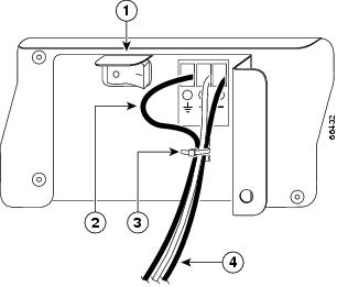
Figure 20 Disconnecting Power from a Cisco uBR7200 Series DC-Input Power Supply
Power switch
-V lead
Power receptacle
M4 studs
DC power supply
+V lead
M5 grounding receptacles
Handle
M5 grounding lug
Step 4
This completes the procedure for disconnecting DC-input power from a Cisco 7200 series router or Cisco uBR7200 series router.
Removing the Input/Output Controller
Note
(See the "Copying the Configuration File to a TFTP Server" section.)
To remove an I/O controller from a Cisco 7200 series router or Cisco uBR7200 series router, complete the following steps:
Step 1
Step 2
Step 3
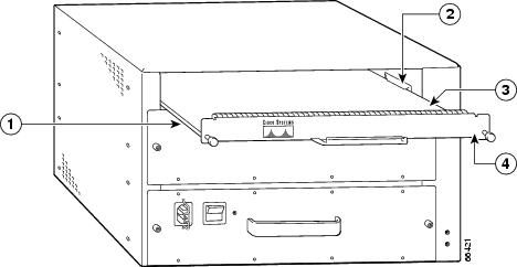
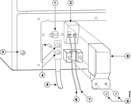
(if present) ports. (For a Cisco 7200 series router, see Figure 21. For a Cisco uBR7200 series router, see Figure 22.)Figure 21 Cisco 7200 Series Input/Output Controller and Ports
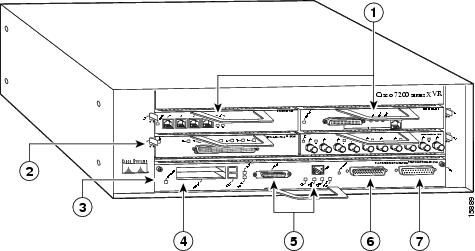
Port adapter
MII and RJ-45 Fast Ethernet ports
Port adapter latch
Auxiliary port
I/O controller
Console port
PC Card slots
Figure 22 Cisco uBR7200 Series Input/Output Controller Ports, Handle, and Captive Installation Screws (Cisco uBR7246 Shown)
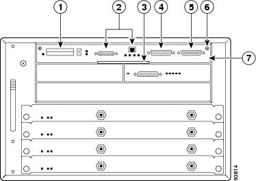
PC Card slots
Console port
Fast Ethernet port (MII port and RJ-45 port)
Captive installation screw
Handle
I/O controller
Auxiliary port
Step 4
Step 5
Note
Step 6
Caution
Step 7
This completes the procedure for removing an installed I/O controller.
Replacing an Input/Output Controller
To install a new I/O controller in the router, complete the following steps:
Step 1
Step 2
Step 3
Step 4
Caution
Step 5
Note
Cisco 7200 VXR router that is rack-mounted, remove the port adapters, processing engine and I/O controller from the chassis and reinstall them. Install the processing engine and I/O controller in the lowest slots first, then populate the slots above them, in a bottom-to-top order.
Figure 23 Aligning the I/O Controller Printed Circuit Board Between the Slot Guides in the Cisco 7200 Series
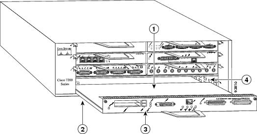
Figure 24 Aligning the I/O Controller Printed Circuit Board Between the Slot Guides in the Cisco uBR7200 Series (Cisco uBR7246 Shown)
Caution
Step 6
Step 7
Step 8
Step 9
This completes the procedure for replacing the I/O controller in a Cisco 7200 series router or Cisco uBR7200 series router.
Reconnecting Input Power and Powering Up the Router
The following procedures explain how to reconnect input power to a Cisco 7200 series router or Cisco uBR7200 series router, power up the router, and verify a successful system boot.
Warning
Statement 10
To see translations of the warnings that appear in this publication, refer to the Regulatory Compliance and Safety Information document that accompanied this device.
Reconnecting AC-Input Power
To reconnect AC-input power to a Cisco 7200 series router or Cisco uBR7200 series router, complete the following steps:
Step 1
Step 2
Step 3
Figure 25 Connecting AC-Input Power to a Cisco 7200 Series Router

Power switch
Power cable-retention clip
Power cord
Handle with hole for cable tie
PWR OK LED
Figure 26 Connecting AC-Input Power to a Cisco uBR7200 Series Universal Broadband Router
Cable-retention clip
AC power cable
Power receptacle
Power switch
Captive installation screw
Handle
Step 4
Note
For Cisco uBR7200 series routers, each AC-input power supply operating at 120 VAC requires a minimum of 7A service.
We recommend powering Cisco 7200 series routers and Cisco uBR7200 series routers from a 120 VAC, 15A receptacle United States (240 VAC, 10A international) at the power source.
Step 5
This completes the steps for reconnecting AC-input power to a Cisco 7200 series router or Cisco uBR7200 series router. Proceed to the "Powering Up the Router" section.
Reconnecting DC-Input Power
Note
Warning
To see translations of the warnings that appear in this publication, refer to the Regulatory Compliance and Safety Information document that accompanied this device.
Warning
To see translations of the warnings that appear in this publication, refer to the Regulatory Compliance and Safety Information document that accompanied this device.
To reconnect DC-input power to a Cisco 7200 series router or Cisco uBR7200 series router, complete the following steps:
Step 1
Step 2
Figure 27 Connecting DC-Input Power to a Cisco 7200 Series Router
Figure 28 Connecting DC-Input Power to a Cisco uBR7200 Series Universal Broadband Router
Power switch
-V lead
Power receptacle
M4 studs
Captive installation screw
+V lead
M5 grounding receptacles
Handle
M5 grounding lug
Step 3
Figure 29 Stripping the DC-Input Leads
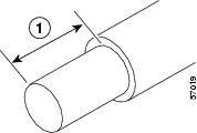
Note
Step 4
•
•
Step 5
Note
Step 6
•
•
Note
A service loop is not required in the lead attached to the grounding lug on Cisco uBR7200 series routers, because this lead is separate from the +V and -V leads and is secured by two M5 nuts to the M5 receptacles.
Step 7
Figure 30 Replacing the Strain-Relief Cover on a Cisco uBR7200 Series DC-Input Power Supply
Power switch
-V lead
Power
+V lead
Captive installation screw
Strain-relief cover
M5 grounding receptacles
M4 nuts
M5 grounding lug
Step 8
Note
For Cisco uBR7200 series routers, each DC-input power supply rating is 14A, 700 volt amperes (VA).
Warning
To see translations of the warnings that appear in this publication, refer to the Regulatory Compliance and Safety Information document that accompanied this device.
Step 9
This completes the steps for reconnecting DC-input power to a Cisco 7200 series router or Cisco uBR7200 series router.
Powering Up the Router
To power up a Cisco 7200 series router or Cisco uBR7200 series router that has an installed AC-input or DC-input power supply, complete the following steps:
Step 1
•
•
•
•
•
•
•
•
•
•
Caution
Step 2
Step 3
Step 4
Step 5
Cisco Internetwork Operating System SoftwareIOS (tm) 7200 Software (C7200-J-M), Version 11.1(9) [kpfjrgiu 100]Copyright (c) 1986-1996 by cisco Systems, Inc.Compiled Sun 21-Apr-96 04:10 by
This completes the procedures for connecting input power and powering up the router.
Downloading the Saved Configuration from the TFTP Server
After you install a new I/O controller in the router and verify a successful router boot, you must retrieve the router configuration from the TFTP server and copy it to NVRAM. Use the copy tftp running-config command to copy the saved configuration from the TFTP file server. The system prompts you for a host name and address, the name of the configuration file stored on the host, and confirmation to reboot using the remote file.
If you replaced an I/O controller without the Fast Ethernet port with an I/O controller with the Fast Ethernet port, you will most likely want to configure the new interface after retrieving the router configuration from the TFTP server and copying it to NVRAM.
Before retrieving the router configuration file from the TFTP file server, check the following:
•
•
•
•
Before configuring the new interface on the I/O controller, be prepared with the following information:
•
•
For complete descriptions of interface commands and the configuration options available for Cisco 7200 series and Cisco uBR7200 series-related interfaces, refer to the documentation resources listed in the "Related Documentation" section.
To retrieve the saved router configuration from the remote host, complete the following steps:
Step 1
Note
Step 2
Step 3
Router# copy tftp running-configStep 4
Host or network configuration file [host]?Step 5
IP address of remote host [255.255.255.255]? 10.1.1.1Step 6
Name of configuration file [router-confg]?Step 7
Configure using router-confg from 10.1.1.1? [confirm]Booting router-confg from 10.1.1.1: ! ! [OK - 874/16000 bytes]While the router retrieves and boots from the configuration on the remote host, the console display indicates whether or not the operation was successful. A series of exclamation points (!!!! ) and [OK] (as shown in the preceding example) indicate that the operation was successful. A series of periods ( . . ). and [timed out] or [failed] indicate a failure (which would probably be due to a network fault or an incorrect server name, address, or filename). The following is an example of a failed attempt to boot from a remote server:
Booting Router-confg ..... [timed out]•
•
Step 8
Step 9
This completes the procedure for downloading the saved router configuration from the remote host. Proceed to the following section, "Configuring the I/O Controller Interfaces," if you installed an I/O controller with an Ethernet, Fast Ethernet, or Gigabit Ethernet interface. If you installed an I/O controller without any Ethernet interfaces, this completes the procedure for replacing the I/O controller in a Cisco 7200 series router or Cisco uBR7200 series router. Proceed to the "Connection Equipment and Port Signaling" section for additional information you might need when replacing an I/O controller in a Cisco 7200 series router or Cisco uBR7200 series router.
Configuring the I/O Controller Interfaces
This section describes the configuration commands you need to configure the different interfaces on your I/O controller. Interface attributes that can be configured on your I/O controller include media type, transmission mode, and speed. Table 12 lists the models, their interface types, default settings, and the commands to change the defaults.
Table 12 I/O Controller Interface Configuration Commands and Defaults
C7200-I/O
None
—
—
C7200-I/O-FE
Fast Ethernet (RJ-45 or MII)
RJ-45 port (100BASE-T)
media-type mii
media-type 100basetHalf-duplex
duplex {full | half}
no duplex1C7200-I/O-FE-MII
Fast Ethernet (MII only)
Half-duplex
duplex {full | half}
no duplex1C7200-I/O-GE+E
Ethernet (Ethernet is not configurable in Cisco IOS Release 12.0 S.)
Autonegotiation
duplex {full | half | auto}
no duplex1Gigabit Ethernet
Autonegotiation
C7200-I/O-2FE/E
2 independent autosensing4 Ethernet/
Fast Ethernet (Ethernet is not configurable in Cisco IOS Release 12.0 S.)Autonegotiation
duplex {full | half | auto}
no duplex1Autonegotiation
speed {10 | 100 | auto}
1 The no duplex command returns the transmission mode to the default value set for that port.
2 Enables full-duplex operation, 1000-Mbps speed, and flow control.
3 The no negotiation auto command turns the interface to the force link mode. The force link mode turns off the flow control. Transmission mode and speed remains set at full duplex and 1000 Mbps, respectively.
4 To fully enable autonegotiation on the Ethernet/Fast Ethernet interfaces, use the defaults: duplex auto and speed auto (Fast Ethernet only). For autonegotiation to work correctly, the interface at the other end of the link (link partner) must also be able to support autonegotiation. If autonegotiation is not supported, the Ethernet/FastEthernet interface defaults to half-duplex operation and you may have to configure the duplex manually.
Note
If you are running a Cisco IOS software release earlier than Cisco IOS Release 12.0 T or Cisco IOS Release 12.0 XE or Cisco IOS Release 12.0 S, you must use the full-duplex command instead of the duplex {full | half | auto} command to change transmission mode. Use the no full-duplex command to return to half-duplex mode. Autoduplex selection is not available in these releases.
Configuring Interface Media Type
For the I/O controller with both an MII and an RJ-45 Fast Ethernet port (C7200-I/O-FE), you need to configure the media type for the port you want to use. The RJ-45 port is the default media type for this I/O controller. Use the media-type command to change the I/O controller media type and the show interfaces command to verify the change.
The following example configures the MII port as the media type for the C7200-I/O-FE:
Router# configure terminalEnter configuration commands, one per line. End with CNTL/Z.Router(config)# interface fastethernet 0/0Router(config-if)# media-type miiRouter(config-if)#no shutdownRouter(config-if)# exitRouter(config)#%LINEPROTO-5-UPDOWN: Line protocol on Interface FastEthernet0/0, changed state to up%LINK-3-UPDOWN: Interface FastEthernet0/0, changed state to upRouter# show interfaces fastethernet 0/0FastEthernet0/0 is administratively up, line protocol is up(display text omitted)Encapsulation ARPA, loopback not set, keepalive not set, hdx, MII(display text omitted)Use the media-type 100baset command to return the media type to the RJ-45 port.
Note
Configuring Interface Transmission Mode
The default transmission mode for the 10BASET/100BASETX autosensing Ethernet/Fast Ethernet interfaces on the C7200-I/O-2FE/E model is auto.
The default transmission mode for the Fast Ethernet port on the C7200-I/O-FE and C7200-I/O-FE-MII I/O controller models is half-duplex. The auto command option is not available for these models.
Use the duplex {full | half | auto} command to change the Fast Ethernet port transmission mode, and use the show interfaces command to verify the change as follows:
Router# configure terminalEnter configuration commands, one per line. End with CNTL/Z.Router(config)# interface fastethernet 0/0Router(config-if)# duplex fullRouter(config-if)#no shutdownRouter(config-if)# exitRouter(config)#%LINEPROTO-5-UPDOWN: Line protocol on Interface FastEthernet0/0, changed state to up%LINK-3-UPDOWN: Interface FastEthernet0/0, changed state to upRouter# show interfaces fastethernet 0/0FastEthernet0/0 is administratively up, line protocol is up(display text omitted)Encapsulation ARPA, loopback not set, keepalive not setKeepalive set (10 sec) Full-duplex, l00MB, 100BaseTXUse the no duplex command to return the Fast Ethernet port on the I/O controller to its default transmission mode. (For default listings for each model, see Table 12.)
Note
Note
Configuring Interface Speed
The I/O controller C7200-I/O-2FE/E has two 10BASET/100BASETX autosensing Ethernet/Fast Ethernet interfaces equipped with RJ-45 ports. To configure these interfaces, use the duplex command and the speed command. The default transmission mode is auto and the default interface speed is auto. To fully enable autonegotiation on the Ethernet/Fast Ethernet interfaces, use the duplex auto command and the speed auto command. To change the default settings, use the following command options for Cisco IOS Release 12.1 E and Cisco IOS Release 12.1 T only:
duplex {full | half | auto}no duplexspeed {10 | 100 | auto}no speedPerforming a Basic Configuration
The following procedure explains a basic configuration for an Ethernet, Fast Ethernet, or Gigabit Ethernet interface on the I/O controller. In the following procedure, press the Return key after each step unless otherwise noted. At any time, you can exit the privileged level and return to the user level by entering disable at the prompt as follows:
Router#disableRouter>
Note
In the Cisco 7206 or Cisco 7206VXR router shelf, you identify interfaces by shelf number, port adapter slot number, and interface port number (shelf/slot/port). The shelf number is a number assigned to the router shelf during the initial configuration of the Cisco AS5800 universal access server. Port adapter slot 0 in the router shelf is also reserved for ports on the I/O controller. Therefore, the address of the port on the I/O controller (if present) in a router shelf is y/0/x, where y is the shelf number and x is the interface port number. For information about the Cisco 7206 and Cisco 7206VXR as router shelves in a Cisco AS5800 universal access server, refer to the Cisco AS5800 universal access server documentation listed in the "Related Documentation" section.
Step 1
Router# configure terminalEnter configuration commands, one per line. End with CNTL/Z.Router(config)#Step 2
Router(config)# interface fastethernet 0/0
Note
Step 3
Router(config-int)# ip address 10.1.1.10 255.255.255.0Step 4
Router(config-if)# media-type mii
Note
Step 5
Router(config-if)# duplex fullStep 6
Router(config-if)#no shutdownRouter(config-if)# exitRouter(config)#%LINEPROTO-5-UPDOWN: Line protocol on Interface FastEthernet0/0, changed state to up%LINK-3-UPDOWN: Interface FastEthernet0/0, changed state to upStep 7
Router(config)#Ctrl-ZRouter#Step 8
Router# copy running-config startup-config[OK]Router#Step 9
Router# show interfaces fastethernet 0/0FastEthernet0/0 is administratively up, line protocol is up(display text omitted)Encapsulation ARPA, loopback not set, keepalive not setKeepalive set (10 sec) Full-duplex, l00MB, 100BaseTX(display text omitted)
Note
This completes the procedure for a basic configuration of the I/O controller interfaces.
Using show Commands to Check the Installation
Use show commands to identify the hardware installed in your router, to verify the operation status, to view interface configuration settings, and to troubleshoot your router configuration. The interfaces on your I/O controller are identified by chassis slot number and interface port number (slot/port). The chassis slot number for the I/O controller is always slot 0. Table 13 lists the I/O controller models, their corresponding interfaces, and the interface addressing syntax for each interface.
Table 13 Identifying Interface Addresses
C7200-I/O-GE+E
Gigabit Ethernet (port GE 0)
Chassis slot—always 0
Interface port—0
0/0
Ethernet (port E 0)
Chassis slot—always 0
Interface port—0
0/0
C7200-I/O-2FE/E
Fast Ethernet/Ethernet (port 0)
Chassis slot—always 0
Interface port—0
0/0
Fast Ethernet/Ethernet (port 1)
Chassis slot—always 0
Interface port—1
0/1
C7200-I/O-FE1
Fast Ethernet (MII or RJ-45)
Chassis slot—always 0
Interface port—0
0/0
C7200-I/O
No interface ports
—
—
C7200-I/O-FE-MII2
Fast Ethernet (MII)
Chassis slot—always 0
Interface port—0
0/0
1 The product number C7200-I/O-FE does not specify MII because both an MII and an RJ-45 port are included.
2 The I/O controller with the product number C7200-I/O-FE-MII has a single MII Fast Ethernet port only. Although still supported by Cisco Systems, this I/O controller with a single MII port is no longer an orderable product as of April 1998.
This remainder of this section provides examples of show commands that pertain to the I/O controller.
Note
Note
Use the show interfaces command to check the status of an interface and to see how it is configured. The following example shows the status and configuration settings for the Gigabit Ethernet interface.
Router# show interfaces gigabitethernet 0/0GigabitEthernet0/0 is up, line protocol is upHardware is 82543 (Livengood), address is 00d0.ffb6.4c00 (bia 00d0.ffb6.4c00)Internet address is 11.1.1.3/8MTU 1500 bytes, BW 1000000 Kbit, DLY 10 usec,reliability 255/255, txload 1/255, rxload 1/255Encapsulation ARPA, loopback not setKeepalive set (10 sec)Full-duplex mode, link type is autonegotiation, media type is SXoutput flow-control is on, input flow-control is onARP type:ARPA, ARP Timeout 04:00:00Last input 00:00:04, output 00:00:03, output hang neverLast clearing of "show interface" counters neverQueueing strategy:fifoOutput queue 0/40, 0 drops; input queue 0/75, 0 drops5 minute input rate 0 bits/sec, 0 packets/sec5 minute output rate 0 bits/sec, 0 packets/sec2252 packets input, 135120 bytes, 0 no bufferReceived 2252 broadcasts, 0 runts, 0 giants, 0 throttles0 input errors, 0 CRC, 0 frame, 0 overrun, 0 ignored0 watchdog, 0 multicast, 0 pause input0 input packets with dribble condition detected2631 packets output, 268395 bytes, 0 underruns0 output errors, 0 collisions, 2 interface resets0 babbles, 0 late collision, 0 deferred0 lost carrier, 0 no carrier, 0 pause output0 output buffer failures, 0 output buffers swapped outUse the show controllers command to display initialization block information, transmit ring, receive ring, and errors for the I/O controllers. The following sample is output for the show controllers gigabitethernet command.
Router# show controllers gigabitethernet 0/0Interface GigabitEthernet0/0 (idb 0x61677314)Hardware is i82543 A1network connection mode is AUTOnetwork link is uploopback type is noneSERDES is enabled (TBI mode), GBIC is enabledGBIC type is 1000BaseSXi82543 MAC registers:CTRL =0x1ACC0004, STATUS=0x00000FAB, CTRL_X=0x000048E0, IMS =0x00000096RCTL =0x00428032, RDBAL =0x2000E000, RDBAH =0x00000000, RDLEN =0x00001000RDH =0x00000009, RDT =0x00000008, RDTR =0x00000000TCTL =0x000400FA, TDBAL =0x20010000, TDBAH =0x00000000, TDLEN =0x00001000TDH =0x0000000B, TDT =0x0000000B, TIPG =0x00600806ETT =0x00000000, TXDMAC=0x00000001TXCW =0xC00001A0, RXCW =0xDC0041A0, FCRTH =0x0000AFF0, FCRTL =0x80001200FCAH =0x00000100, FCAL =0x00C28001, FCT =0x00008808, FCTTV =0x00000080RDFH =0x00000195, RDFT =0x00000195, RDFPC =0x00000000TDFH =0x00001A1C, TDFT =0x00001A1C, TDFPC =0x00000000RX is normal, enabled TX is normal, enabledDevice status = full-duplex, link upAuto-neg - doneAuto-neg - bit sync OK, Received idle stream, invalid symbol, idle charsAuto-neg - Partner Ability is Pause Capable, Asymmetric FC, FDGBIC registers:Register 0x00: 01 00 01 00 00 00 01 00Register 0x08: 00 00 00 00 0D 00 00 00Register 0x10: 32 1E 00 00 4D 65 74 68Register 0x18: 6F 64 65 20 45 6C 65 63Register 0x20: 2E 20 20 20 00 00 00 00Register 0x28: 4D 47 42 43 2D 32 30 2DRegister 0x30: 34 2D 31 2D 53 20 20 20Register 0x38: 31 30 30 30 00 00 00 55Register 0x40: 00 0A 00 00 41 41 46 59Register 0x48: 43 35 39 20 20 20 20 20Register 0x50: 20 20 20 20 39 39 30 37Register 0x58: 32 36 20 20 00 00 00 7DPartNumber:MGBC-20-4-1-SPartRev:GSerialNo:AAFYC59Options: 0Length(9um/50um/62.5um):000/500/300Date Code:990726Gigabit Ethernet Codes: 1PCI configuration registers:bus_no=0, device_no=8DeviceID=0x1001, VendorID=0x8086, Command=0x0156, Status=0x0230Class=0x02/0x00/0x00, Revision=0x01, LatencyTimer=0xFC, CacheLineSize=0x20BaseAddr0=0x48100000, BaseAddr1=0x00000000, MaxLat=0x00, MinGnt=0xFFSubsysDeviceID=0x1001, SubsysVendorID=0x8086Cap_Ptr=0x000000DC Retry/TRDY Timeout=0x00000000PMC=0x00220001 PMCSR=0x00000000i82543 Internal Driver Information:lc_ip_turbo_fs=0x6040C2C0, ip_routecache=0x1(dfs=0/mdfs=0)i82543_ds=0x61678F60, registers=0x3C100000rx cache size=1000, rx cache end=744, rx_nobuffer=0max_mtu=1524ring sizes:RX=256, TX=256rxring=0x2000E000, shadow=0x616792C0, head=9, rx_buf_size=512txring=0x20010000, shadow=0x616796EC, head=11, tail=11chip_state=2, pci_rev=1tx_count=0, tx_limited=0rx_overrun=0, rx_seq=0, rx_no_enp=0, rx_discard=0throttled=0, enabled=0, disabled=0, fake_disabled=0reset=9(init=1, check=0, restart=3, pci=0), auto_restart=9link_reset=0, tx_carrier_loss=0, fatal_tx_err=0isl_err=0, wait_for_last_tdt=0HW addr filter:0x61679F18, ISL disabled, Promiscuous mode multicastEntry= 0: Addr=0000.CACA.BEBE(display text omitted)Use the show diag 0 command to identify the I/O controller that is installed in your Cisco 7200 series router or Cisco uBR7200 series router.
Note
Note
The following example of the show diag 0 command shows an installed C7200-I/O-FE that is equipped with an MII port and an RJ-45 port:
Router> show diag 0Slot 0:Fast-ethernet on C7200 I/O with MII or RJ45 port adapter, 1 portPort adapter is analyzedPort adapter insertion time 00:10:42 agoHardware revision 2.0 Board revision A0Serial number 3511336 Part number 73-1537-03Test history 0x0 RMA number 00-00-00EEPROM format version 1EEPROM contents (hex):0x20: 01 14 02 00 00 35 94 28 49 06 01 03 00 00 00 000x30: 50 0000 00 FF FF FF FF FF FF FF FF FF FF FF FFThe following example of the show diag 0 command is from a Cisco 7202 that has an installed I/O controller with the Fast Ethernet port. The following text in the command output indicates that the Fast Ethernet port on the I/O controller is disabled:
Port adapter disabledRouter> show diag 0Slot 0:Fast-ethernet on C7200 I/O with MII or RJ45 port adapter, 1 portPort adapter disabledPort adapter insertion time 00:10:42 agoHardware revision 2.0 Board revision A0Serial number 3511336 Part number 73-1537-03Test history 0x0 RMA number 00-00-00EEPROM format version 1EEPROM contents (hex):0x20: 01 14 02 00 00 35 94 28 49 06 01 03 00 00 00 000x30: 50 0000 00 FF FF FF FF FF FF FF FF FF FF FF FFTroubleshooting Using the show interfaces fastethernet Command
Intel Corporation has changed the specifications for its Peripheral Component Interconnect (PCI) bus with a Fast Ethernet hardware interface. These changes have been incorporated into certain Cisco hardware products. For most users, this change is transparent. However, an anomaly has been identified when this updated Cisco hardware is used in conjunction with certain releases of Cisco IOS software. This section explains the anomaly and how to work around it.
Anomaly Details
When you use the Cisco IOS software show interfaces fastethernet command, output similar to the following is normally displayed:
Router# show interfaces fastethernet [slot/port]FastEthernet0/0 is up, line protocol is upHardware is DEC21140, address is 00e0.f74f.dc00 (bia 00e0.f74f.dc00)Internet address is 192.168.255.1MTU 1500 bytes, BW 100000 Kbit, DLY 100 usec, rely 255/255, load 1/255Encapsulation ARPA, loopback not setKeepalive set (10 sec)Half-duplex, 100Mb/s, MIIARP type: ARPA, ARP Timeout 04:00:00Last input never, output 00:00:06, output hang neverLast clearing of "show interface" counters neverQueueing strategy: fifoOutput queue 0/40, 0 drops; input queue 0/75, 0 drops5 minute input rate 0 bits/sec, 0 packets/sec5 minute output rate 1000 bits/sec, 0 packets/sec0 packets input, 0 bytesReceived 0 broadcasts, 0 runts, 0 giants, 0 throttles0 input errors, 0 CRC, 0 frame, 0 overrun, 0 ignored0 watchdog, 0 multicast0 input packets with dribble condition detected51 packets output, 11872 bytes, 0 underruns0 output errors, 0 collisions, 0 interface resets0 babbles, 0 late collision, 0 deferred0 lost carrier, 0 no carrier0 output buffer failures, 0 output buffers swapped outWhen you enter this command using Cisco IOS software Release 11.1(10) or earlier, or Release 11.2(4) or earlier with updated Cisco hardware, the "overrun" field (shown in bold in the output above) is always zero.
If you use this command because you are troubleshooting potential network problems, you may be expecting to see a number in the overrun field.
Anomaly Workaround
To work around this problem, enter the following Cisco IOS software command to obtain an overrun value:
Router# show controllers fastethernet FE-slot number/0The following output is normally displayed:
Hardware is DEC21140dec21140_ds=0x603531A0, registers=0x4D800000, ib=0x300612C0rx ring entries=64, tx ring entries=128rxring=0x300613C0, rxr shadow=0x603532C0, rx_head=5, rx_tail=0txring=0x30061800, txr shadow=0x60353400, tx_head=33, tx_tail=33, tx_count=0PHY link upFar End Fault Indication (For FX Interface): OFFCSR0=0xFE02E080, CSR3=0x300613C0, CSR4=0x30061800, CSR5=0xFC660000CSR6=0x320CA002, CSR7=0xFFFFA261, CSR8=0xE0400000, CSR9=0xFFFDC3FFCSR11=0xFFFE0000, CSR12=0xFFFFFF09, CSR15=0xFFFFFEC8DEC21140 PCI registers:bus_no=2, device_no=0CFID=0x00091011, CFCS=0x22800006, CFRV=0x02000022, CFLT=0x0000FF00CBIO=0x08312001, CBMA=0x01800000, CFIT=0x28140100, CFDA=0x00000000MII registers:Register 0x00: 2000 784F 2000 5C01 0081 0000 0000 0000Register 0x08: 0000 0000 0000 0000 0000 0000 0000 0000Register 0x10: 0000 0000 0000 0009 0000 0001 8060Register 0x18: 8020 0820 0000 3800 A3B9:(display text omitted):The field that indicates overrun is CSR8 (shown in bold in the output above). This field is in hexadecimal format. To determine an overrun value, take the first four (high-order) digits, drop the first one from the left, convert the remaining three digits to the decimal equivalent, and then divide that number in half.
In the example above, overflows are recorded in CSR8 = 0xE0400000. To determine the overflow value from this example, take the first four (high-order) digits (E040), drop the first digit (E), and convert the remaining number (040) to the decimal equivalent (64). Then divide that number in half. The overrun value in this example is 32.
Troubleshooting
Use Table 14 to diagnose problems.
Table 14 Troubleshooting
C7200-I/O-GE+E or C7200-I/O-2FE/E
—
•
•
•
•
If the router is up, download the correct boot helper (boot loader) image from Cisco.com and replace the down-rev boot helper in boot flash memory.
If the router does not come up (is stuck in ROMmon), boot from other Flash devices (PCMCIA). See Table 11 on page 21 for the correct boot helper (boot loader) image. For information on accessing Cisco.com, see page 82.—
When booting with an C7200-I/O-GE+E or C7200-I/O-2FE/E I/O controller with 12.0(6)S c7200-boot-mz boot loader image:
•
•
PA-3-NOTSUPPORTEDBYLOADER: Port
Adapter type 534 in bay 0 is not
supported by this boot loader
Use the c7200-kboot-mz enhanced boot loader image in Cisco IOS Release 12.0(14)S, 12.1(3a)E, or 12.1(5)T or later releases of Cisco IOS Releases 12.0 S, 12.1 E, and 12.1 T.
—
The Cisco uBR7246VXR router does not recognize the UBR7200-I/O-2FE/E
I/O controller and displays the following warning message:%UBR7200-3-IONOTSUPPORTEDBYLOADER: I/O Controller (type 533) is not supported by this boot loader. The I/O Controller network interfaces will be unavailable.Use only the Cisco IOS Release 12.1(10)EC version of the ubr7200-boot-mz image (ubr7200-boot-mz.121-10.EC), or later Release 12.1 EC version, as your boot helper (boot loader) image for the UBR7200-I/O-2FE/E I/O controller.
—
The Cisco uBR7223 or Cisco uBR7246 router does not boot or recognize the UBR7200-I/O-2FE/E I/O controller.
The UBR7200-I/O-2FE/E controller supports only the Cisco uBR7246VXR router.
—
Cannot insert the I/O controller in the chassis
The C7200-I/O-GE+E and the C7200-I/O-2FE/E I/O controllers operate only in Cisco 7204VXR, Cisco 7206VXR, and Cisco uBR7246VXR chassis.
—
The following error message displays:
%c7200-3-IONOTSUPPORTEDBYLOADER: I/O
controller (type 539) is not supported
by this boot loader. The I/O
controller network interfaces will be
unavailable.
You are attempting to use the standard boot image. These I/O controllers require the c7200-kboot-mz enhanced boot image for full functionality. Update the boot image in boot flash.
NPE-100 and NPE-150
The router powers down immediately after being powered on. (The NPE-100 and NPE-150 require that there be a boot ROM present on the I/O controller; however, the C7200-I/O-GE+E and the C7200-I/O-2FE/E I/O controllers do not have a boot ROM component.)
The NPE-100 and NPE-150 are not supported with the C7200-I/O-GE+E or C7200-I/O-2FE/E I/O controllers.
NPE-175
The system software automatically disables the ports on the I/O controller.
The NPE-175 is not supported with the C7200-I/O-GE+E or C7200-I/O-2FE/E I/O controller.
NPE-200
The router boots from ROMMON but a variety of errors occurs when attempting to boot IOS. The router may hang, crash with a PCI bus error, or fail to recognize PCMCIA cards.
The NPE-200 is not supported with the C7200-I/O-GE+E or C7200-I/O-2FE/E I/O controller.
C7200-I/O-GE+E
NPE-225
Error message at bootup:
PA-3-UNSUPPORTED: PA in slot0
(GigabitEthernet/Ethernet (with
GBIC/RJ45) I/O Card) is not supported
on this chassis or npe cpu card
The NPE-225 is not supported with the C7200-I/O-GE+E I/O controller.
C7200-I/O-2FE/E
NPE-225
The router does not work.
The C7200-I/O-2FE/E I/O controller in a Cisco 7204VXR or Cisco 7406VXR only operates with this version of NPE-225:
board label 72-3453-05 rev AO or higher, or faceplate label 800-05418-03 AO or higher.To check for the correct NPE-225 version in software, use the show c7200 command. Under CPU EEPROM, look for Hardware Revision 1.3 or higher.
Replace the NPE-225 with the correct version: NPE-225 board label 72-3453-05 rev AO or higher, or faceplate label 800-05418-03 AO or higher.
C7200-I/O-FE
—
Cisco 7202 router displays the following message:
%c7200-3-UNSUPPORTED: FE in slot0 is
not supported on a c7202 chassis.
Remove the C7200-I/O-FE I/O controller from the Cisco 7202 router and install a C7200-I/O controller.
—
You cannot upgrade the UBR7200-I/O-FE I/O controller to the Cisco IOS Release 12.1(10)EC boot helper image because of the following error message:
%Error copying
ubr7200-boot-mz.121-10.EC (No space
left on device)
You cannot use the Cisco IOS Release 12.1(10)EC version of the ubr7200-boot-mz boot helper (boot loader) image with the UBR7200-I/O-FE I/O controller. Instead, use the boot helper image from Cisco IOS Release 12.0(15)SC.
—
Only one port is operational at a time.
Use only one port, either the RJ-45 port or the MII port, not both. The port adapter has one port, but a choice of ports.
Connection Equipment and Port Signaling
This section contains connection equipment and pinout information for the Ethernet, Fast Ethernet, Gigabit Ethernet, console, and auxiliary ports that are located on the I/O controller.
Note
Ethernet and Fast Ethernet RJ-45 Connection Equipment
The I/O controller has RJ-45 ports for Ethernet, Fast Ethernet, or autosensing Ethernet and Fast Ethernet connections, depending on your model. The RJ-45 ports support IEEE 802.3(Ethernet), and IEEE 802.3u (Fast Ethernet) interfaces compliant with 10BASET and 100BASETx specifications.
The RJ-45 ports support standard straight-through and crossover Category 5 UTP cables with RJ-45 connectors. (See Figure 35.) Cisco Systems does not supply Category 5 UTP cables; these cables are available commercially.
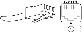
Figure 31 shows an RJ-45 port and connector. Table 15Table 15 lists the pinouts and signals for the RJ-45 port.
Figure 31 RJ-45 Port and Connector
Warning
Table 15 RJ-45 Port Pinouts
1
TxD+1
2
TxD-
3
RxD+2
6
RxD-
1 TxD = Transmit Data.
2 RxD = Receive Data.
Note
Caution
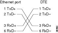
Depending on your I/O controller RJ-45 interface cabling requirements, use the pinouts shown in Figure 32 and Figure 33 for straight-through and crossover twisted-pair cable connections.
Figure 32 Straight-Through Cable Pinout, Ethernet Port to a Hub or Repeater
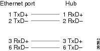
Figure 33 Crossover Cable Pinout, Ethernet Port to a DTE
To determine whether a UTP cable is a crossover cable or a straight-through cable, hold the two RJ-45 connectors next to each other so you can see the colored wires inside the ends, as shown in Figure 34.
Figure 34 Crossover or Straight-Through Cable Identification
Examine the sequence of colored wires to determine the type of cable, as follows:
•
•
Fast Ethernet MII Connection Equipment
The MII port on the I/O controller is a 40-pin, D-shell-type connector that is configurable for 100 megabits per second (Mbps). The MII port supports IEEE 802.3u interfaces compliant with the 100BASEX and 100BASET standards. The MII connection requires an external transceiver that permits connection to 100BASEFX or 100BASET4 physical media. (See Figure 35.)
Figure 35 Fast Ethernet Port Connection
Optional Fast Ethernet port (MII port and RJ-45 port)
To transceiver, repeater, or DTE
MII connector
To repeater or DTE
RJ-45 connector
Caution
Note
The type of media you use between the MII connection and your router, switch, or hub determines the appropriate connectors for the network side of your 100BASET transceiver.
Figure 36 shows the pin orientation of the MII port on the I/O controller.
The MII port uses 2-56 screw-type locks, called jackscrews, to secure the cable or transceiver to the port. MII cables and transceivers have knurled thumbscrews that you fasten to the jackscrews on the MII port and tighten with your fingers. Use the jackscrews to secure your MII cable to the MII port.
Figure 36 MII Port
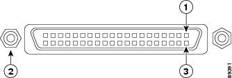
Table 16 lists the pinouts and signals for the I/O controller MII port.
Table 16 MII Port Pinout
14-17
—
Yes
—
Transmit Data (TxD)
12
Yes
—
—
Transmit Clock (Tx_CLK)1
11
—
Yes
—
Transmit Error (Tx_ER)
13
—
Yes
—
Transmit Enable (Tx_EN)
3
—
Yes
—
MII Data Clock (MDC)
4-7
Yes
—
—
Receive Data (RxD)
9
Yes
—
—
Receive Clock (Rx_CLK)
10
Yes
—
—
Receive Error (Rx_ER)
8
Yes
—
—
Receive Data Valid (Rx_DV)
18
Yes
—
—
Collision (COL)
19
Yes
—
—
Carrier Sense (CRS)
2
—
—
Yes
MII Data Input/Output (MDIO)
22-39
—
—
—
Common (ground)
1, 20, 21, 40
—
—
—
+5.0 volts (V)
1 Tx_CLK and Rx_CLK are provided by the external transceiver.
Gigabit Ethernet GBIC Connection Equipment
The Gigabit Interface Converter (GBIC) port is a 1000-Mbps optical interface in the form of an SC-type duplex port that supports IEEE 802.3z interfaces compliant with the 1000BASEX standard. (See Figure 37.)
Note
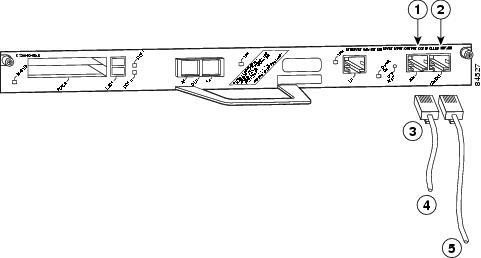
Figure 37 shows the simplex and duplex SC-type connectors on your multimode or single-mode optical fiber cables. For simplex connectors, two cables are required, one cable for transmit (TX) and a second cable for receive (RX). For duplex connectors, one cable that has both TX and RX connectors is required. You can use either simplex or duplex connectors for the C7200-I/O-GE+E.
Figure 37 GBIC Port Connections
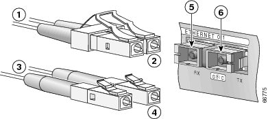
To external 1000BASEX network
2 simplex connectors
1 duplex connector (TX and RX)
TX
To external 1000BASEX network
RX
Note
Table 17 describes the available GBIC options and their product numbers.
Table 18 provides cabling specifications for the GBICs that you install in Gigabit Ethernet devices. Note that all GBIC ports have SC-type connectors. Also, the minimum cable distance for the GBIC-SX or WS-G5484 and GBIC-LX/LH or WS-G5486 (multimode fiber [MMF] and single-mode fiber [SMF]) is 6.5 feet (2 m), and the minimum link distance for the GBIC-ZX or WS-G5487 is 6.2 miles (10 km) with an 8-dB attenuator installed at each end of the link. Without attenuators, the minimum link distance for the GBIC-ZX or WS-G5487 is 24.9 miles (40 km).
Note
Table 18 GBIC Port Cabling Specifications
Cable DistanceSX
850
MMF1
62.5
160
722 ft (220 m)
62.5
200
902 ft (275 m)
50.0
400
1640 ft (500 m)
50.0
500
1804 ft (550 m)
LX/LH
1300
MMF2 and SMF
62.5
500
1804 ft (550 m)
50.0
400
1804 ft (550 m)
50.0
500
1804 ft (550 m)
9/10
—
6.2 miles (10 km)
ZX
1550
SMF
9/10
—
43.5 miles (70 km)
SMF3
8
—
62.1 miles (100 km)
1 Multimode fiber (MMF) only.
2 A mode-conditioning patch cord (product number CAB-GELX-625 or equivalent) is required.
When using the GBIC-LX/LH or WS-G5486 with 62.5-micron diameter MMF, you must install a mode-conditioning patch cord between the GBIC and the MMF cable on both the transmit and the receive ends of the link when link distances are greater than 984 ft (300 m).
We do not recommend using the GBIC-LX/LH or WS-G5486 and MMF with no patch cord for very short link distance (tens of meters). The result could be an elevated bit error rate (BER).3 Dispersion-shifted single-mode fiber-optic cable.
A mode-conditioning patch cord can be used with the GBIC-LX/LH or WS-G5486 to allow reliable laser transmission between the single-mode laser source on the GBIC and a multimode optical fiber cable. (For more information, refer to the installation and configuration guide for your Cisco 7200 series router.)
Warning
Warning
Warning
Console and Auxiliary Port Connection Equipment
The I/O controller has a DCE-mode console port for connecting a console terminal, and a DTE-mode auxiliary port for connecting a modem or other DCE device (such as a CSU/DSU or other router) to your router.
Note
The I/O controller uses two types of physical media for console port and auxiliary port connections. Table 19 describes the I/O controller console and auxiliary port media type for each model.
Before connecting a terminal to the console port, configure the terminal to match the router console port as follows: 9600 baud, 8 data bits, no parity, 2 stop bits (9600 8N2). After you establish normal router operation, you can disconnect the terminal.
For console and auxiliary port pinouts for each media type, see the "DB-25 Port Cabling and Pinouts" section and the "RJ-45 Port Cabling and Pinouts" section.
DB-25 Port Cabling and Pinouts
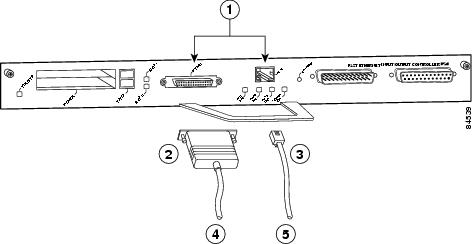
The DB-25 ports and connectors conform to the EIA/TIA-232 serial data transfer standard for communications between DTE and DCE equipment. Figure 38 shows console and auxiliary port connections for DB-25 physical media.
Figure 38 Console and Auxiliary Port DB-25 Connections
DB-25 Console Port Signals and Pinouts
Both Data Set Ready (DSR) and Data Carrier Detect (DCD) are supported on the C7200-I/O, C7200-I/O-FE, and C7200-I/O-FE-MII I/O controller and are active when the system is running. The Request To Send (RTS) signal tracks the state of the Clear To Send (CTS) input. The console port does not support modem control or hardware flow control. Table 20Table 20 lists the DB-25 console port signals for the C7200-I/O, C7200-I/O-FE, and C7200-I/O-FE-MII I/O controllers. The console port requires a straight-through EIA/TIA-232 cable.
Table 20 Console Port Signals for C7200-I/O, C7200-I/O-FE, and C7200-I/O-FE-MII
1
GND
—
Ground
2
TxD
In
Transmit Data
3
RxD
Out
Receive Data
6
DSR
Out
Data Set Ready (always on)
7
GND
—
Ground
8
DCD
Out
Data Carrier Detect (always on)
1 Any pin not referenced is not connected.
DB-25 Auxiliary Port Signals and Pinouts
Table 21Table 21 lists the DB-25 auxiliary port signals for the C7200-I/O, C7200-I/O-FE, and C7200-I/O-FE-MII I/O controllers. The auxiliary port supports hardware flow control and modem control.
Table 21 Auxiliary Port Signals for C7200-I/O, C7200-I/O-FE, and C7200-I/O-FE-MII
2
TxD
Out
Transmit Data
3
RxD
In
Receive Data
4
RTS
Out
Request To Send (used for hardware flow control)
5
CTS
In
Clear To Send (used for hardware flow control)
6
DSR
In
Data Set Ready
7
GND
—
Signal Ground
8
DCD
In
Data Carrier Detect (used for modem control)
20
DTR
Out
Data Terminal Ready (used for modem control only)
1 Any pin not referenced is not connected.
RJ-45 Port Cabling and Pinouts
For the C7200-I/O-GE+E and C7200-I/O-2FE/E I/O controllers, both the console and auxiliary ports use rollover cables with RJ-45 connectors. Adapters are available for connection to modems and other external communications equipment. (See Table 23.)
With an I/O controller installed in the router with an NPE-G1, the default console and auxiliary ports are on the I/O controller, and you cannot access the console and auxiliary ports on the NPE-G1.
Note
Before connecting a terminal to the console port, configure the terminal to match the router console port as follows: 9600 baud, 8 data bits, no parity, 2 stop bits (9600 8N2). After you establish normal router operation, you can disconnect the terminal.
Note
Table 22 Pinouts for the RJ-45-to-DB-25 Adapters
1
4
5
5
2
20
6
8
3
2
3
3
4
7
7
7
5
7
7
7
6
3
2
2
7
6
20
20
8
5
4
4
1 The female data terminal equipment (FDTE) adapter that is available from Cisco is labeled "Terminal".
2 The MMOD adapter that is available from Cisco is labeled "Modem".
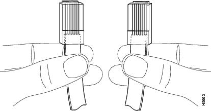
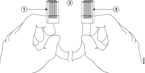
Refer to Table 22 for a list of the pins used on the RJ-45-to-DB-25 adapters, used with an RJ-45 cable, to connect terminals and modems to the Cisco7200 series routers. The cable you use may be a roll-over cable or a straight cable.
A roll-over cable can be detected by comparing the two modular ends of the cable. Holding the cables in your hand, side-by-side, with the tab at the back, the wire connected to the pin on the outside of the left plug should be the same color as the pin on the outside of the right plug. If your cable was purchased from Cisco, pin 1 will be white on one connector, and pin 8 will be white on the other (a roll-over cable reverses pins 1 and 8, 2 and 7, 3 and 6, and 4 and 5). (See Figure 39.)
Figure 39 Identifying a Rollover Cable
The Cisco 7200 series routers ships with a rolled cable. Connection to a terminal or a modem will require an RJ-45-to-DB-25 adapter, and possibly a DB-25-to-DB9 adapter. Refer to Table 23 for the cable and adapter configurations that can be used to connect terminals and modems to the Cisco 7200 series routers.
Table 23 Asynchronous Device Cabling Options
Console or auxiliary
Rolled
FDTE1
Terminal
Console or auxiliary
Straight
FDCE
Terminal
Auxiliary or console
Rolled
MMOD2
Modem
1 The FDTE RJ-45-to-DB-25 adapter is labeled "Terminal".
2 The MMOD RJ-45-to-DB-25 adapter is labeled "Modem".
Both ports are configured as asynchronous serial ports. Figure 40 shows the RJ-45 console and auxiliary port connections.
Figure 40 Console and Auxiliary Port RJ-45 Connections
A cable and adapter kit is available from Cisco Systems (product number ACS-2500ASYN=). Table 22 describes the cable and adapter configurations that can be used to connect terminals and modems to the console or the auxiliary port.
RJ-45 Console Port Signals and Pinouts
The C7200-I/O-2FE/E and C7200-I/O-GE+E I/O controller console ports do not support Data Carrier Detect (DCD). Table 24 lists the RJ-45 console port signals for the C7200-I/O-2FE/E and C7200-I/O-GE+E I/O controllers.
RJ-45 Auxiliary Port Signals and Pinouts
Table 25 lists the RJ-45 auxiliary port signals for the C7200-I/O-2FE/E and C7200-I/O-GE+E I/O controllers.
Table 25 Auxiliary Port Signals for C7200-I/O-2FE/E and C7200-I/O-GE+E
1
RTS
Out
Ready To Send
2
DTR
Out
Data Terminal Ready
3
TXD
Out
Transmit Data
41
RING
In
Ring Indication
5
GND
—
Signal Ground
6
RXD
In
Receive Data
72
DSR/DCD(RLSD)
In
Data Set Ready / Data Carrier Detect (Receive Line Signal Detect)
8
CTS
In
Clear To Send (tracks RTS)
1 RING is not supported on Cisco-supplied adapters. To use this pin, you must create a customized cable.
2 Pin 7 can be used as a DCD input for connection to a modem. The RJ-45-to-DB-25F adapter maps DCD to this pin when used with a straight-through cable. (See Table 22.)
Upgrading the Boot Helper (Boot Loader) Image
The boot helper (boot loader) image resides in Flash memory on the I/O controller and contains a subset of the Cisco IOS software. This image is used to boot your router from the network or to load Cisco IOS images onto the router. This image is also used if the system cannot find a valid system image.
Your boot helper (boot loader) image should correspond to the Cisco IOS release that is running on your router. When you upgrade your Cisco IOS software to the minimum required software release (see Table 11), we recommend that you also upgrade your boot helper (boot loader) image.
Note
Note
Note
Note
%c7200-3-IONOTSUPPORTEDBYLOADER: I/O controller (type 539) is not supported by this boot loader. The I/O controller network interfaces will be unavailable.
To upgrade your boot helper (boot loader) image, obtain the most current boot helper image through Cisco.com and copy the new boot helper image to Flash memory on your router. For information on how to access Cisco.com, see the "Obtaining Documentation and Submitting a Service Request" section. Follow the Software Center link under Service and Support. You need to Login to retrieve files from the Software Center.
To obtain a boot helper (boot loader) image from Cisco.com and upgrade your boot flash memory, do the following:
Step 1
Step 2
router# format bootflash:Format operation may take a while. Continue? [confirm]Format operation will destroy all data in "bootflash:". Continue? [confirm]Formatting sector ...Format of bootflash:complete
Note
Step 3
router# copy tftp bootflash:Address or name of remote host []? biffSource filename []? c7200-boot-mz.120-5.SDestination filename [c7200-boot-mz.120-5.S]?Accessing tftp://biff/c7200-boot-mz.120-5.S...Loading c7200-boot-mz.120-5.S from 192.168.254.254 (via Ethernet4/0):!!!!!!!!!!!!!!!!!!!!!!!!!!!!!!!!!!!!!!!!!!!!!!!!!!!!!!!!!!!!!!!!!!!!!!!!!!!!!!!!!!!!!!!!!!!!!!!!![OK - 3132516/6264832 bytes]3132516 bytes copied in 28.488 secs (111875 bytes/sec)
This completes the procedure for upgrading your boot helper (boot loader) image. For more detailed instructions on loading and maintaining system images and microcode, including boot helper images, refer to the Configuration Fundamentals Configuration Guide, which is available on Cisco.com.
Installing and Removing a Flash Memory Card or Flash Disk
The I/O controller has two PC Card slots: slot 0 (lower) and slot 1 (upper). (See Figure 41.)
Note
Note
The "Reformatting a Flash Memory Card or Flash Disk" section explains how to reformat a Flash memory card.
To install a Flash memory card in either PC Card slot, complete the following steps:
Step 1
(See Figure 41.)Step 2
Figure 41 Installing and Removing a Flash Memory Card
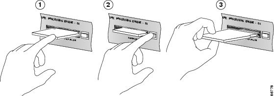
Inserting the Flash memory card
Removing the Flash memory card
Pushing the eject button for the Flash memory card
Note
Some older Flash memory cards might have foil tape attached to the outside edge of the card. If you insert one of these cards into the upper PC Card slot (slot 1) of an I/O controller installed in a Cisco uBR7200 series router, it might be difficult to remove the card. You should use a new Flash memory card that does not have the foil tape, remove the foil tape from the older Flash memory card, or, if necessary, use small pliers to remove the Flash memory card.
This completes the procedure for installing a Flash memory card in either PC Card slot.
To remove a Flash memory card from either PC Card slot, complete the following steps:
Step 1
Step 2
Step 3
This completes the procedure for removing a Flash memory card from either PC Card slot.
Reformatting a Flash Memory Card or Flash Disk
Depending on the circumstances, you might need to use a Flash memory card from another system to copy images or back up configuration files; however, you cannot boot from a Flash memory card that was formatted on another type of system. You must reformat the card before you can use it as a boot source.
Note
Note
Caution
The formatting procedure assumes the following:
•
•
Note
•
Use the following procedure to reformat a Flash memory card:
Step 1
Note
Step 2
Router> enablePassword: passwordRouter#copy slot0:image.name tftpEnter destination file name [image.name]:image.name CCCCCCCCCCCCCCCCCCCCCCCCCCCCCCCCCCCCCCCCCCCCCCCCCCCC CCCCCCCCCCCCCCCCCCCCCCCCCCCCCCCCCCCCCCCCCCCCCCCCCCAddress or name of remote host [tftp.server.name]?tftp.server.name !!!!!!!!!!!!!!!!!!!!!!!!!!!!!!!!!!!!!!!!!!!!!!!!!!!!!!!!!!!!!!!!!!!!!!!!!!!!!!!!!!!!!!!!!!!!Router#Step 3
Router# format slot0:All sectors will be erased, proceed? [confirm]Enter volume id (up to 30 characters): MyNewCardFormatting sector 1Format device slot0 completedRouter#Step 4
Router# copy tftp slot0Enter source filename: image.name20575008 bytes available on device slot0, proceed? [confirm]address or name of remote host [tftp.server.name]? tftp.server.nameloading new.image from tftp.server.name (via Ethernet1/0):!!!!!!!!!!!!!!!!!!!!!!!!!!!!!!!!!!!!!!!!!!!!!!!!!!!!!!!!!!!!!!!!!!!!!!!!!!!!!!!!!!!!!!!!!!!!!!!!!!!!!!!!!!!!!!!!!!!!!!!!!!!!!!!!!!!!!!!!!!!!!!![OK - 7799951/15599616 bytes]CCCCCCCCCCCCCCCCCCCCCCCCCCCCCCCCCCCCCCCCCCCCCCCCCCCCCCCCCCCCCCCCCCCCCCCCCCCCCCCCCCCCCCRouter#
The Flash memory card is now reformatted and ready to use.
Fiber Optic Cleaning Information
We strongly recommend cleaning all optical fiber connections before reconnecting optical cables to equipment. For information about cleaning optical connectors, see the Inspection and Cleaning Procedures for Fiber-Optic Connections document and the Compressed Air Cleaning Issues for Fiber-Optic Connections document..
FCC Class A Compliance
This equipment has been tested and found to comply with the limits for a Class A digital device, pursuant to part 15 of the FCC rules. These limits are designed to provide reasonable protection against harmful interference when the equipment is operated in a commercial environment. This equipment generates, uses, and can radiate radio-frequency energy and, if not installed and used in accordance with the instruction manual, may cause harmful interference to radio communications. Operation of this equipment in a residential area is likely to cause harmful interference, in which case users will be required to correct the interference at their own expense.
You can determine whether your equipment is causing interference by turning it off. If the interference stops, it was probably caused by the Cisco equipment or one of its peripheral devices. If the equipment causes interference to radio or television reception, try to correct the interference by using one or more of the following measures:
•
•
•
•
Note
Note
Obtaining Documentation and Submitting a Service Request
For information on obtaining documentation, submitting a service request, and gathering additional information, see the monthly What's New in Cisco Product Documentation, which also lists all new and revised Cisco technical documentation, at:
http://www.cisco.com/en/US/docs/general/whatsnew/whatsnew.html
Subscribe to the What's New in Cisco Product Documentation as a Really Simple Syndication (RSS) feed and set content to be delivered directly to your desktop using a reader application. The RSS feeds are a free service and Cisco currently supports RSS version 2.0.
To open a service request by telephone, use one of the following numbers:
Asia-Pacific: +61 2 8446 7411 (Australia: 1 800 805 227)
EMEA: +32 2 704 55 55
USA: 1 800 553-2447For a complete list of Cisco TAC contacts, go to this URL:
http://www.cisco.com/techsupport/contacts
Obtaining Additional Publications and Information
Information about Cisco products, technologies, and network solutions is available from various online and printed sources.
•
http://www.cisco.com/go/marketplace/
•
•
•
http://www.cisco.com/go/iqmagazine
or view the digital edition at this URL:
http://ciscoiq.texterity.com/ciscoiq/sample/
•
•
http://www.cisco.com/en/US/products/index.html
•
http://www.cisco.com/discuss/networking
•
http://www.cisco.com/en/US/learning/index.html

This document is to be used in conjunction with the documents listed in the "Related Documentation" section.

Copyright © 2008, Cisco Systems, Inc.
All rights reserved


 Feedback
Contact Cisco
- Open a Support Case

- (Requires a Cisco Service Contract)