Table Of Contents
280-Watt DC-Input Power Supply Replacement Instructions
DC-Input Power Supply Overview
Rules for Chassis with Dual Power Supplies
Electrical Equipment Guidelines
Ensuring Easy Access to the Router
Removing and Replacing a DC-Input Power Supply
Single Power Supply Configuration
Powering Down the Router and Disconnecting DC-Input Power
Removing the DC-Input Power Supply
Replacing the DC-Input Power Supply
Reconnecting DC-Input Power and Turning On the Power Supply
Dual Power Supply Configuration
Rules for Chassis with Dual Power Supplies
Turning Off the Power Supply and Disconnecting DC-Input Power
Removing the DC-Input Power Supply
Replacing the DC-Input Power Supply
Reconnecting DC-Input Power and Turning On the Power Supply
Cisco Product Security Overview
Reporting Security Problems in Cisco Products
Obtaining Technical Assistance
Cisco Technical Support & Documentation Website
Definitions of Service Request Severity
Obtaining Additional Publications and Information
280-Watt DC-Input Power Supply Replacement Instructions
Product Number: PWR-7200-DC=, PWR-7200-DC+, PWR-7200-DC+=, PWR-7200/2-DC+ , MAS-7200PSCOVER=, RS7206S=, RS7206VXR=, CISCO7204VXR=, CISCO7206VXR=
Introduction
This document explains how to remove and replace the 24V or 48V 280-Watt (W) DC-input power supply in the Cisco 7200 series routers—which consist of the two-slot Cisco 7202, four-slot Cisco 7204 and Cisco 7204VXR, and the six-slot Cisco 7206 and Cisco 7206VXR. It includes instructions for powering down the router, removing an installed power supply, and installing a new power supply. This document also includes steps for verifying the initialization of the system after you power up the router.
Note The Cisco 7206VXR and Cisco 7206 can be used as router shelves in a Cisco AS5800 Universal Access Server. References to the Cisco 7200 series routers in this document include the Cisco 7206VXR and Cisco 7206 as router shelves in a Cisco AS5800 Universal Access Server, unless indicated otherwise.
Contents
The following sections are included in this document:
•DC-Input Power Supply Overview
•Removing and Replacing a DC-Input Power Supply
•Cisco Product Security Overview
•Obtaining Technical Assistance
•Obtaining Additional Publications and Information
Related Documentation
For Cisco IOS software configuration information and support, refer to the modular configuration and modular command reference publications in the Cisco IOS software configuration documentation set that corresponds to the software release installed on your Cisco hardware.
Your Cisco 7200 VXR router and the Cisco IOS software running on it contain extensive features and functionality, which are documented in the following resources:
•Cisco 7200 Series Routers Documentation Roadmap at http://www.cisco.com/univercd/cc/td/doc/product/core/7200vx/3512.htm for a list of all Cisco 7200 series routers documentation and troubleshooting tools and information.
–For hardware installation and maintenance information on the Cisco 7200 VXR routers, refer to .
For hardware installation and maintenance information on the Cisco 7200 routers, refer to
Cisco 7206 Router Quick Start Guide
–For international agency compliance, safety, and statutory information for wide-area network (WAN) interfaces for the Cisco 7200 series routers refer to the following publications:
Regulatory Compliance and Safety Information for the Cisco 7200 Series Routers
•Cisco 7200 Series Routers Port Adapter Documentation Roadmap at http://www.cisco.com/univercd/cc/td/doc/product/core/7200vx/3530.htm for a list of all Cisco 7200 series routers-supported port adapter documentation.
•Cisco 7200 Series Routers Troubleshooting Documentation Roadmapat http://www.cisco.com/univercd/cc/td/doc/product/core/7200vx/3518.htm for links to troubleshooting tools, utilities, and Tech Notes.
•For hardware installation, maintenance, and regulatory information and software configuration information on the Cisco AS5800 Universal Access Server, refer to the following publications:
–Cisco AS5800 Universal Access Server Hardware Installation Guide
–Cisco AS5800 Universal Access Server Regulatory Compliance and Safety Information
•For general information about documentation, refer to the "Obtaining Documentation" section on page 22.
•For customer support information, see the "Obtaining Technical Assistance" on page 23.
DC-Input Power Supply Overview
The Cisco 7200 series routers are equipped with a single DC-input power supply (when DC-input power is specified). An optional, second DC-input power supply is available for the router; it must be ordered as a spare. The router operates with one installed power supply; however, the second power supply provides hot-swappable, load-sharing redundant power.
Two 280W DC-input power supplies are available:
•A 48V power supply (PWR-7200-DC=)
This power supply operates from 48V to 60V.
•A 24V power supply (PWR-7200-DC+, PWR-7200-DC+=, PWR-7200/2-DC+)
This power supply operates from 24V to 60V.
The faceplates of both 280W DC-input power supplies have a green OK LED, a power switch, a handle for removing, installing, and handling the power supply, three DC-input lead receptacles, and two captive installation screws. (See Figure 1.)
Figure 1 Cisco 7200 Series DC-Input Power Supply Faceplate
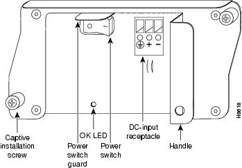
The power supply handle provides a grip point for pulling the power supply out of the router (refer to Figure 1). Two captive installation screws secure the power supply in the router. Three DC-input leads (-, +[return], and ground) connect the DC-input power supply to the site DC power source.
A cable tie is shipped with each DC-input power supply to secure the leads to the power supply faceplate and provide strain relief for the leads.
LEDs
Use the following table for LED status information.
Rules for Chassis with Dual Power Supplies
•Chassis with dual power supplies, operating in a 24V environment, must use two 24V power supplies. If one 48V power supply is placed in a system requiring a 24V environment, the 48V power supply does not work. It does not cause any damage to the system.
•Chassis with dual power supplies, operating in a 48V environment, may use two 48V power supplies, two 24V power supplies, or one of each.
Caution Do not mix AC- and DC-input power supplies in the same router.
Figure 2 24V Power Supply Ratings Label
To distinguish the two power supplies, look for these characteristics:
•The 48V power supply sheet metal finish is shiny.
•The 24V power supply sheet metal finish is dull.
•The 24V label located on the power supply next to the cable connector reads 24 - 60 V. (See Figure 2.)
•The 48V label located on the power supply next to the cable connector reads 48 - 60V.
Software Requirements
The 24V power supply requires one of these four minimum Cisco IOS Releases:
•Cisco IOS Release 12.1(7)E or later releases
•Cisco IOS Release 12.2(2)T or later releases
•Cisco IOS Release 12.2(3) or later releases
•Cisco IOS Release 12.0(17)S or later releases
Power Supply Specifications
Note Site wiring and circuit breakers or fuses should be chosen to meet local safety requirements.
Table 3 Voltage and Current Maximum Values
Nominal Voltage Current (A)24 VDC
Minimum 19A service
48 VDC
Minimum 13A service
60 VDC
Minimum 8A service
Note The values in Table 3 are absolute maximum values. Typical system configurations use substantially less. To obtain typical values for your configuration, contact your Cisco sales representative.
This product relies on the building's installation for short-circuit (overcurrent) protection. Ensure that a listed and certified fuse or circuit breaker, 35A maximum 60 VDC, is used on all current-carrying conductors. Site wiring and circuit breakers need to be sized to accommodate the maximum values (noted in the preceding table) for safety reasons.
Installation Prerequisites
This section provides a list of parts and tools you need to remove and replace the DC-input power supply in the Cisco 7200 series routers. This section also includes safety and ESD-prevention guidelines to help you avoid injury to yourself and damage to the equipment.
Tools and Parts Required
You need the following parts and tools to remove and replace the DC-input power supply. If you need additional equipment, contact a service representative for ordering information.
•A new DC-input power supply (PWR-7200-DC) or (PWR-7200-DC+, PWR-7200-DC+=, PWR-7200/2-DC+) (See "Rules for Chassis with Dual Power Supplies" section if the router has two power supplies.)
•Standard wire stripper
•Number 2 Phillips and a 3/16-inch flat-blade screwdriver
•Several cable ties (if the router is mounted in an equipment rack)
Note Wiring information—voltage and current maximum values—is provided in Table 3.
Safety Guidelines
Following are safety guidelines that you should follow when working with any equipment that connects to electrical power or telephone wiring.
Safety Warnings
Warning Only trained and qualified personnel should be allowed to install or replace this equipment.
Statement 1030
Electrical Equipment Guidelines
Follow these basic guidelines when working with any electrical equipment:
•Before beginning any procedures requiring access to the chassis interior, locate the emergency power-off switch for the room in which you are working.
•Disconnect all power and external cables before moving a chassis.
•Do not work alone when potentially hazardous conditions exist.
•Never assume that power has been disconnected from a circuit; always check.
•Do not perform any action that creates a potential hazard to people or makes the equipment unsafe; carefully examine your work area for possible hazards such as moist floors, ungrounded power extension cables, and missing safety grounds.
•A DC circuit breaker sized to protect the site wiring is recommended for the DC input power source. This circuit breaker should protect against short-circuit and overcurrent faults in accordance with United States National Electrical Code NFPA 70 (United States), Canadian Electrical Code, part I, C22.1 (Canada) and IEC 364 (other countries).
•Only a DC power source that complies with the safety extra-low voltage (SELV) requirements in ULL950, CSA 950, EN 60950, and IEC950 can be connected to the DC-input power supply.
•A readily accessible disconnect device must be incorporated in the fixed wiring.
•This unit is to be installed in a restricted access area in accordance with articles 110-16, 110-17, and 110-18 of the National Electric Code, ANSI/NFPA 70.
Telephone Wiring Guidelines
Use the following guidelines when working with any equipment that is connected to telephone wiring or to other network cabling:
•Never install telephone wiring during a lightning storm.
•Never install telephone jacks in wet locations unless the jack is specifically designed for wet locations.
•Never touch uninsulated telephone wires or terminals unless the telephone line has been disconnected at the network interface.
•Use caution when installing or modifying telephone lines.
Ensuring Easy Access to the Router
If your Cisco 7200 series router is installed in a standard 19-inch, four-post or telco rack, cables from other equipment in the rack might obstruct access to the rear of the router. Also, rack power strips or other permanent fixtures may obstruct access to the router. Review the following guidelines to ensure easy access to the rear of the router when it is installed in a rack. If the router is not installed in a rack, or if you already have clear access to the rear of the router, proceed to the following section "Removing and Replacing a DC-Input Power Supply."
Use the following guidelines to ensure easy access to the rear of the router when it is installed in a rack:
•Ensure that you have at least three to four feet of working space at the rear of the router.
•If cables from other equipment in the rack fall in front of the rear end of the router, carefully gather the cables (using care not to strain them) and use cable ties to anchor them away from the rear of the router.
•If access to the rear of the router is partially blocked by a power strip or some other permanent rack fixture, detach the router from the rack and carefully slide it forward until there is enough clearance to remove the power supply, the network processing engine or network services engine, and the subchassis from the router. Detailed steps for detaching the router from the rack are contained in the following section "Removing and Replacing a DC-Input Power Supply."
Caution Make sure that at least one other person is available to support the front of the router as you slide it out from the rack and, if necessary, to continue to support it while you remove and insert the power supply, network processing engine or network services engine, or subchassis.
Removing and Replacing a DC-Input Power Supply
The following sections explain how to remove and replace a DC-input power supply in Cisco 7200 series routers.
Note The procedures for removing and replacing a DC-input power supply in a single or dual power supply configuration are the same for the Cisco 7200 series routers and the Cisco 7206 and Cisco 7206VXR when used as router shelves in the Cisco AS5800 Universal Access Server. Therefore, the illustrations and procedures in the following sections apply to the Cisco 7200 series and the Cisco AS5800 Universal Access Server router shelf unless indicated otherwise.
Single Power Supply Configuration
The procedures for removing and replacing the DC-input power supply in a single power supply configuration are explained in the following sections:
•Powering Down the Router and Disconnecting DC-Input Power
•Removing the DC-Input Power Supply
•Replacing the DC-Input Power Supply
•Reconnecting DC-Input Power and Turning On the Power Supply
Powering Down the Router and Disconnecting DC-Input Power
To power down Cisco 7200 series routers that have an installed DC-input power supply, complete the following steps:
Note Before powering down the router, use the copy running-config startup-config command to save the router's running configuration to nonvolatile memory.
Caution This unit might have more than one power cord. To reduce the risk of electric shock, disconnect the two power cords before servicing the router. Statement 83
Caution The DC return connection to this system is to remain isolated from the system frame and chassis (DC-I).
Step 1 Facing the rear of the router, place the power switch (on the power supply) in the off (O) position. (See Figure 3.)
Step 2 Observe the following items:
•The green OK LED on the power supply turns off.
•The fans stop operating.
•The LEDs on the I/O controller turn off.
•The LEDs on the port adapters turn off.
Step 3 Turn off the power source and disconnect the DC-input power leads from the power source. You can leave the ground cable connected.
This completes the procedure for powering down Cisco 7200 series routers.
To disconnect DC-input power to the Cisco 7200 series routers, complete the following steps:
Warning Before completing any of the following steps, and to prevent short-circuit or shock hazards, ensure that power is removed from the DC circuit. To ensure that all power is OFF, locate the circuit breaker on the panel board that services the DC circuit, switch the circuit breaker to the OFF position, and tape the switch handle of the circuit breaker in the OFF position. Statement 322
Warning When installing the unit, the ground connection must always be made first and disconnected last. Statement 42
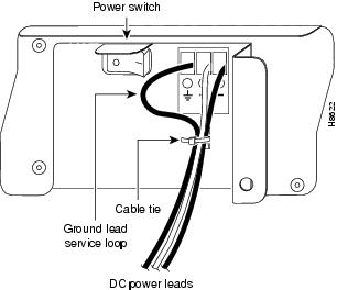
Figure 3 Disconnecting Power from a Cisco 7200 Series DC-Input Power Supply
Step 1 At the rear of the router, make sure that the power switch on the power supply is in the off (O) position. (For the Cisco 7200 series routers, see Figure 3.)
Step 2 Ensure that no current is flowing through the DC power supply leads. To ensure that all power is off, locate the circuit breaker on the panel board that services the DC circuit, switch the circuit breaker to the off position, and tape the switch handle of the circuit breaker in the off position.
Step 3 Disconnect the -V and +V and ground leads from the power supply.
Step 4 Remove the cable tie that secures the DC power line input leads and ground leads to the power supply faceplate. Save the cable tie.
Note The cable tie that accompanied your DC-input power supply can be removed and replaced on the power supply without the use of a tool. If you secured the DC-input power supply leads to the power supply faceplate using a different type of cable tie, use the wire stripper to cut that cable tie from the power supply.
Step 5 Using a 3/16-inch flat-blade screwdriver, loosen the screw below the +DC power line input lead receptacle and pull the lead from the connector (see Figure 3). Repeat this step for the -DC power power input lead and the ground lead.
Note The color coding of the DC-input power supply leads depends on the color coding of the DC power source at your site. Typically, green or green/yellow is used for ground. Make certain the lead color coding you choose for the DC-input power supply matches lead color coding used at the DC power source.
This completes the procedure for disconnecting DC-input power. Proceed to the section, "Removing the DC-Input Power Supply."
Removing the DC-Input Power Supply
To remove the DC-input power supply from Cisco 7200 series routers, complete the following steps:
Step 1 Using a number 2 Phillips or a 3/16-inch flat-blade screwdriver, loosen the two captive installation screws on the faceplate of the power supply. (See Figure 4.)
If the router is not installed in a standard 19-inch, four-post or telco rack, skip to Step 5. If the router is installed in a rack, determine if any permanent rack fixtures, such as a power strip, are obstructing access to the power supply. If a rack fixture is obstructing access to the power supply, proceed to Step 2.
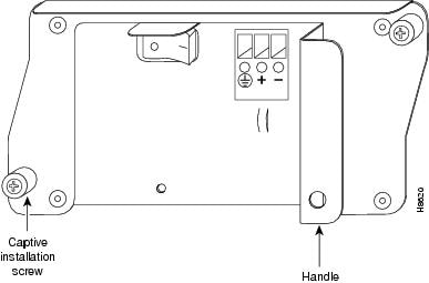
Figure 4 Captive Installation Screws and Handle on the DC-Input Power Supply
Step 2 Using a 3/16-inch flat-blade screwdriver, loosen the screws that secure the router to the front mounting strips of the rack.
Step 3 Position at least one person in front of the rack to support the front underside of the router.
Step 4 From the rear of the rack, carefully push the front of the router out of the rack until there is enough clearance to remove the power supply.
Step 5 Grasp the power supply handle and pull the DC-input power supply from the router.
Caution To maintain agency compliance requirements and meet EMI emissions standards for the Cisco 7200 series routers with a single power supply, the power supply filler plate must remain in the power supply adjacent to the installed power supply. Do not remove this filler plate from the router unless you intend to install a redundant power supply.
This completes the procedure for removing the DC-input power supply from Cisco 7200 series routers.
Replacing the DC-Input Power Supply
Caution Do not mix AC- and DC-input power supplies in the same router.
To install a new DC-input power supply in a Cisco 7200 series chassis, complete the following steps:
Step 1 Make sure the power switch on the power supply is in the off (O) position.
Step 2 Grasp the power supply handle with one hand and place your other hand underneath the power supply for support (refer to Figure 5).
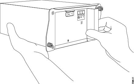
Figure 5 Holding the DC-Input Power Supply
Step 3 Align the power supply to the power supply bay.
Step 4 Slide the power supply completely into the power supply bay until its faceplate is flush with the router's rear panel.
Caution When inserting a power supply into the router, do not use unnecessary force; slamming the power supply into the bay can damage the connectors on the rear of the supply and on the midplane.
Step 5 Seat the power supply in the router by tightening its captive installation screws with a number 2 Phillips or a 3/16-inch flat-blade screwdriver.
Note The power supply is not fully seated in the router midplane until you tighten its captive installation screws.
Step 6 If there is no second power supply, replace the filler plate on the empty power supply bay. Using a number 2 Phillips screwdriver, tighten the filler plate's captive installation screws.
Step 7 If you pushed the router from the rack, slowly guide the router back into the rack.
Step 8 Use a 3/16-inch flat-blade screwdriver to tighten the screws that secure the router to the front mounting strips of the rack.
Caution To maintain agency compliance requirements and meet EMI emissions standards for the Cisco 7200 series routers with a single power supply, the power supply filler plate must remain in the power supply adjacent to the installed power supply. Do not remove this filler plate from the router unless you intend to install a redundant power supply.
This completes the procedures for replacing a DC-input power supply in the router. Proceed to the following section, "Reconnecting DC-Input Power and Turning On the Power Supply."
Reconnecting DC-Input Power and Turning On the Power Supply
The following procedures explain how to reconnect DC-input power to Cisco 7200 series routers, power up the router, and verify a successful system boot.
Warning Read the installation instructions before you connect the system to its power source. Statement 10
Caution The DC return connection to this system is to remain isolated from the system frame and chassis (DC-I).
Note The color coding of the DC-input power supply leads depends on the color coding of the DC power source at your site. Typically, green or green/yellow is used for ground. Make certain the lead color coding you choose for the DC-input power supply matches lead color coding used at the DC power source.
To reconnect DC-input power to Cisco 7200 series routers, complete the following steps:
Warning Before completing any of the following steps, and to prevent short-circuit or shock hazards, ensure that power is removed from the DC circuit. To ensure that all power is OFF, locate the circuit breaker on the panel board that services the DC circuit, switch the circuit breaker to the OFF position, and tape the switch handle of the circuit breaker in the OFF position. Statement 322
Warning When installing the unit, the ground connection must always be made first and disconnected last. Statement 42
Step 1 To ensure that all power is off, locate the circuit breaker on the panel board that services the DC circuit, switch the circuit breaker to the off position, and tape the switch handle of the circuit breaker in the off position. Ensure that the DC power line input leads are disconnected from the power source.
Step 2 If necessary, use a wire stripper to strip approximately 0.55 inch (14 mm) from the DC power line input and ground leads. (See Figure 6.)
Figure 6 Stripping the DC-Input Leads
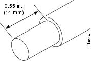
Step 3 At the rear of the router, check that the power switch on the power supply is in the off (O) position. (See Figure 7.)
Step 4 Insert the stripped end of the ground lead all the way into the ground lead receptacle on the DC-input power supply and tighten the receptacle screw using a 3/16-inch flat-blade screwdriver. (See Figure 7.)
Figure 7 Connecting DC-Input Power
Step 5 Insert the stripped end of the + DC power line input lead all the way into the + lead receptacle and tighten the receptacle screw using the same 3/16-inch flat-blade screwdriver. Repeat Step 5 for the -DC power line input lead.
Note Make sure the entire stripped end of each lead is inserted all the way into its receptacle. If any exposed wire at the stripped end of a lead is visible after inserting the lead into its receptacle, remove the lead from the receptacle, use the wire stripper to cut the stripped end of the lead, and repeat Step 2 through Step 5.
Step 6 After tightening the receptacle screw for the ground and DC power line input leads, use the cable tie you saved earlier to secure the three leads to the power supply faceplate.
Note When securing the ground and DC power line input leads to the power supply faceplate, leave a small service loop in the ground lead to ensure that it is the last lead to disconnect from the power supply if a great deal of strain is placed on all three leads (refer to Figure 7).
Step 7 Turn the circuit breaker to the on position to restore power to the DC-input power leads..
Note Each DC-input power supply operating at 24V DC requires a minimum of 19A service.
Each DC-input power supply operating at 48 VDC requires a minimum of 13A service. Each DC-input power supply operating at 60 VDC requires a minimum of 8A service.
The preceding values are absolute maximum values. Typical system configurations use substantially less. To obtain typical values for your configuration, contact your Cisco sales representative.
This product relies on the building's installation for short-circuit (overcurrent) protection. Ensure that a listed and certified fuse or circuit breaker, 35A maximum 60 VDC, is used on all current-carrying conductors. Site wiring and circuit breakers need to be sized to accommodate the maximum values for safety reasons.
This completes the steps for connecting DC-input power to Cisco 7200 series routers.
To power up Cisco 7200 series routers that have an installed DC-input power supply, complete the following steps:
Step 1 Check for the following:
•Each port adapter is inserted in its slot, and its respective port adapter lever is in the locked position.
•The network processing engine or network services engine and the I/O controller are inserted in their respective slots, and their captive installation screws are tightened.
•All network interface cables are connected to the port adapters.
•A Flash Disk or Flash memory card is installed in its PCMCIA slot (if present).
•Each DC lead is connected and secured to the power supply faceplate with a cable tie.
•Each DC lead is connected and secured to the power source.
•The tape (that you applied earlier) is removed from the circuit breaker switch handle, and power is restored by moving the circuit breaker handle to the on position.
•The console terminal is turned on.
Step 2 At the rear of the router, place the power switch on the power supply in the on (|) position. The green OK LED on the power supply turns on.
Step 3 Listen for the fans; you should immediately hear them operating.
Step 4 During the boot process, observe the system's LEDs. The LEDs on most of the port adapters go on and off in irregular sequence. Some may go on, go out, and go on again for a short time. On the I/O controller, the IO power OK LED comes on immediately.
Step 5 Observe the initialization process. When the system boot is complete (a few seconds), the network processing engine or network services engine begins to initialize the port adapters and the I/O controller. During this initialization, the LEDs on each port adapter behave differently (most flash on and off). The enabled LED on each port adapter goes on when initialization is completed, and the console screen displays a script and system banner similar to the following:
Cisco Internetwork Operating System SoftwareIOS (tm) 7200 Software (C7200-J-M), Version 11.1(10)Copyright (c) 1986-1996 by cisco Systems, Inc.Compiled Sun 21-Apr-96 04:10 by
This completes the procedure for replacing the DC-input power supply in a single power supply configuration, reconnecting input power, and powering up the router.
Dual Power Supply Configuration
The procedures for removing and replacing the DC-input power supply in a dual power supply configuration are explained in the following sections:
•Rules for Chassis with Dual Power Supplies
•Turning Off the Power Supply and Disconnecting DC-Input Power
•Removing the DC-Input Power Supply
•Replacing the DC-Input Power Supply
•Reconnecting DC-Input Power and Turning On the Power Supply
Rules for Chassis with Dual Power Supplies
Before beginning the installation, read the following rules:
•Chassis with dual power supplies, operating in a 24V environment, must use two 24V power supplies. If one 48V power supply is placed in a system requiring a 24V environment, the 48V power supply does not work. It does not cause any damage to the system.
•Chassis with dual power supplies, operating in a 48V environment may use two 48V power supplies, two 24V power supplies, or one of each.
Caution Do not mix AC- and DC-input power supplies in the same router.
Figure 8 24V Power Supply Ratings Label
To distinguish the two DC power supplies, look for these characteristics:
•The 48V power supply sheet metal finish is shiny.
•The 24V power supply sheet metal finish is dull.
•The 24V label located on the power supply next to the cable connector reads 24 - 60 V. See (Figure 8.)
•The 48V label located on the power supply next to the cable connector reads 48 - 60V.
Turning Off the Power Supply and Disconnecting DC-Input Power
Warning Before completing any of the following procedures, and to prevent short-circuit or shock hazards, ensure that power is removed from the DC circuit. To ensure that all power is OFF, locate the circuit breaker on the panel board that services the DC circuit, switch the circuit breaker to the OFF position, and tape the switch handle of the circuit breaker in the OFF position. Statement 322
Warning When installing the unit, the ground connection must always be made first and disconnected last. Statement 42
Caution The DC return connection to this system is to remain isolated from the system frame and chassis (DC-I).
Caution It is possible to remove and replace one DC power supply while the router remains powered up and running on the other DC power supply if the two DC power supplies are on separate circuit breakers. If they are on the same circuit breaker, both power supplies must be powered off, and the circuit breaker turned to the off position before replacing one of the power supplies.
To turn off the DC-input power supply you plan to replace and to disconnect power, complete the following steps:
Step 1 Facing the rear of the router, place the power switch (on the power supply you wish to replace) in the off (O) position. The green OK LED on the power supply you are replacing turns off.
Step 2 To ensure that all power (to the power supply you wish to replace) is off, locate the circuit breaker on the panel board that services the DC circuit, switch the circuit breaker to the off position, and tape the switch handle of the circuit breaker in the off position.
Note Assuming the two power supplies are on separate power circuits and can have power to one turned off by turning off the circuit breaker, the second power supply maintains full system power (the system continues to operate as normal).
Step 3 Remove the cable tie that secures the DC power line input leads and ground leads to the power supply faceplate. Save the cable tie.
Note The cable tie that accompanied your DC-input power supply can be removed and replaced on the power supply without using a tool. If you secured the DC-input power supply leads to the power supply faceplate using a different type of cable tie, use the wire stripper to cut the cable tie from the power supply.
Step 4 Using a 3/16-inch flat-blade screwdriver, loosen the screw below the +DC input power lead receptacle and pull the lead from the connector (see Figure 3). Repeat this step for the -DC input power lead and the ground lead.
Note The color coding of the DC-input power supply leads depends on the color coding of the DC power source at your site. Typically, green or green/yellow is used for ground. Make certain the lead color coding you choose for the DC-input power supply matches lead color coding used at the DC power source.
This completes the procedure for disconnecting DC-input power. Proceed to the section, "Removing the DC-Input Power Supply."
Removing the DC-Input Power Supply
To remove the DC-input power supply from Cisco 7200 series routers, complete the following steps:
Step 1 Using a number 2 Phillips or a 3/16-inch flat-blade screwdriver, loosen the two captive installation screws on the faceplate of the power supply (See Figure 4).
If the router is not installed in a standard 19-inch rack or in a telco rack, skip to Step 5. If the router is installed in a rack, determine if any permanent rack fixtures, such as a power strip, are obstructing access to the power supply. If a rack fixture is obstructing access to the power supply, proceed with Step 2.
Step 2 Using a 3/16-inch flat-blade screwdriver, loosen the screws that secure the router to the front mounting strips of the rack.
Step 3 Position at least one person in front of the rack to support the front underside of the router.
Step 4 From the rear of the rack, carefully push the front of the router out of the rack until there is enough clearance to remove the power supply from the router.
Step 5 Grasp the power supply handle and pull the DC-input power supply from the router.
This completes the procedure for removing the DC-input power supply from Cisco 7200 series routers.
Replacing the DC-Input Power Supply
To install a new DC-input power supply in Cisco 7200 series routers, complete the following steps:
Step 1 Make sure the power switch on the power supply is in the off (O) position.
Step 2 Grasp the power supply handle with one hand and place your other hand underneath the power supply for support (refer to Figure 5).
Step 3 Align the power supply to the power supply bay.
Step 4 Slide the power supply completely into the power supply bay until its faceplate is flush with the router's rear panel.
Caution When inserting a power supply into the router, do not use unnecessary force; slamming the power supply into the bay can damage the connectors on the rear of the power supply and on the midplane.
Step 5 Seat the power supply in the router by tightening its captive installation screws with a number 2 Phillips or a 3/16-inch flat-blade screwdriver.
Note The power supply is not fully seated in the router midplane until you tighten its captive installation screws.
Step 6 If you pushed the router forward in the rack, slowly guide the router back into the rack.
Step 7 Use a 3/16-inch flat-blade screwdriver to tighten the screws that secure the router to the front mounting strips of the rack.
This completes the procedures for replacing a DC-input power supply in the router. Proceed to the following section "Reconnecting DC-Input Power and Turning On the Power Supply."
Reconnecting DC-Input Power and Turning On the Power Supply
Warning Read the installation instructions before you connect the system to its power source. Statement 10
Caution The DC return connection to this system is to remain isolated from the system frame and chassis (DC-I).
The following procedures explain how to reconnect DC-input power to Cisco 7200 series routers, turn on the power supply, and verify the power supply is operating properly.
Note The color coding of the DC-input power supply leads depends on the color coding of the DC power source at your site. Typically, green or green/yellow is used for ground. Make certain the lead color coding you choose for the DC-input power supply matches lead color coding used at the DC power source.
To reconnect DC-input power to Cisco 7200 series routers, complete the following steps:
Warning Before completing any of the following procedures, and to prevent short-circuit or shock hazards, ensure that power is removed from the DC circuit. To ensure that all power is OFF, locate the circuit breaker on the panel board that services the DC circuit, switch the circuit breaker to the OFF position, and tape the switch handle of the circuit breaker in the OFF position. Statement 322
Warning When installing the unit, the ground connection must always be made first and disconnected last.
Statement 42
Step 1 Ensure that the DC power line input leads are disconnected from the power source.
Step 2 If necessary, use a wire stripper to strip approximately 0.55 inch (14 mm) from the DC power line input and ground leads. (See Figure 6).
Step 3 At the rear of the router, check that the power switch on the power supply is in the off (O) position (refer to Figure 9).
Step 4 Insert the stripped end of the ground lead all the way into the ground lead receptacle on the DC-input power supply and tighten the receptacle screw using a 3/16-inch flat-blade screwdriver.
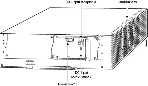
Figure 9 Cisco 7200 Series Power Supply DC Receptacles and Power Switch
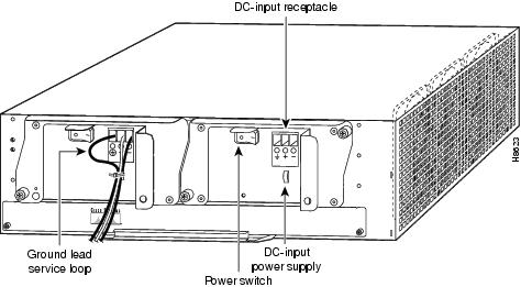
Step 5 Insert the stripped end of the + DC power line input lead all the way into the + lead receptacle and tighten the receptacle screw using the same 3/16-inch flat-blade screwdriver. Repeat Step 5 for the - DC power line input lead.
Note Make sure the entire stripped end of each lead is inserted all the way into its receptacle. If any exposed wire at the stripped end of a lead is visible after inserting the lead into its receptacle, remove the lead from the receptacle, use the wire stripper to cut the stripped end of the lead, and repeat Step 2 through Step 5.
Step 6 After tightening the receptacle screw for the ground and DC power line input leads, use the cable tie you saved earlier to secure the three leads to the power supply faceplate.
Note When securing the ground and DC power line input leads to the power supply faceplate, leave a small service loop in the ground lead to ensure that it is the last lead to disconnect from the power supply if a great deal of strain is placed on all three leads (refer to Figure 9).
Step 7 Connect the ground and DC power line input leads to the power source.
Note Each DC-input power supply operating at 24 VDC requires a minimum of 19A service.
Each DC-input power supply operating at 48 VDC requires a minimum of 13A service. Each DC-input power supply operating at 60 VDC requires a minimum of 8A service.
The preceding values are absolute maximum values. Typical system configurations use substantially less. To obtain typical values for your configuration, contact your Cisco sales representative.
This product relies on the building's installation for short-circuit (overcurrent) protection. Ensure that a listed and certified fuse or circuit breaker, 35A maximum 60 VDC, is used on all current-carrying conductors. Site wiring and circuit breakers need to be sized to accommodate the maximum values for safety reasons.
This completes the steps for connecting DC-input power to Cisco 7200 series routers.
To turn on the power supply, complete the following steps:
Step 1 Place the power switch on the newly installed power supply in the on (|) position. The green OK LED on the power supply turns on.
Step 2 Listen for the fans; you should immediately hear them operating.
Step 3 During the boot process, observe the system's LEDs. The LEDs on most of the port adapters go on and off in irregular sequence. Some may go on, go out, and go on again for a short time. On the I/O controller, the IO power OK LED comes on immediately.
Step 4 Observe the initialization process. When the system boot is complete (a few seconds), the network processing engine or network services engine begins to initialize the port adapters and the I/O controller. During this initialization, the LEDs on each port adapter behave differently (most flash on and off). The enabled LED on each port adapter goes on when initialization is completed, and the console screen displays a script and system banner similar to the following:
Cisco Internetwork Operating System SoftwareIOS (tm) 7200 Software (C7200-J-M), Version 11.1(10)Copyright (c) 1986-1996 by cisco Systems, Inc.Compiled Sun 21-Apr-96 04:10 by
This completes the procedure for removing and replacing the DC-input power supply in a dual power supply configuration, reconnecting input power, and turning on the power supply.
Obtaining Documentation
Cisco documentation and additional literature are available on Cisco.com. Cisco also provides several ways to obtain technical assistance and other technical resources. These sections explain how to obtain technical information from Cisco Systems.
Cisco.com
You can access the most current Cisco documentation at this URL:
http://www.cisco.com/techsupport
You can access the Cisco website at this URL:
You can access international Cisco websites at this URL:
http://www.cisco.com/public/countries_languages.shtml
Product Documentation DVD
Cisco documentation and additional literature are available in the Product Documentation DVD package, which may have shipped with your product. The Product Documentation DVD is updated regularly and may be more current than printed documentation.
The Product Documentation DVD is a comprehensive library of technical product documentation on portable media. The DVD enables you to access multiple versions of hardware and software installation, configuration, and command guides for Cisco products and to view technical documentation in HTML. With the DVD, you have access to the same documentation that is found on the Cisco website without being connected to the Internet. Certain products also have .pdf versions of the documentation available.
The Product Documentation DVD is available as a single unit or as a subscription. Registered Cisco.com users (Cisco direct customers) can order a Product Documentation DVD (product number DOC-DOCDVD=) from Cisco Marketplace at this URL:
http://www.cisco.com/go/marketplace/
Ordering Documentation
Beginning June 30, 2005, registered Cisco.com users may order Cisco documentation at the Product Documentation Store in the Cisco Marketplace at this URL:
http://www.cisco.com/go/marketplace/
Nonregistered Cisco.com users can order technical documentation from 8:00 a.m. to 5:00 p.m. (0800 to 1700) PDT by calling 1 866 463-3487 in the United States and Canada, or elsewhere by calling 011 408 519-5055. You can also order documentation by e-mail at tech-doc-store-mkpl@external.cisco.com or by fax at 1 408 519-5001 in the United States and Canada, or elsewhere at 011 408 519-5001.
Documentation Feedback
You can rate and provide feedback about Cisco technical documents by completing the online feedback form that appears with the technical documents on Cisco.com.
You can send comments about Cisco documentation to bug-doc@cisco.com.
You can submit comments by using the response card (if present) behind the front cover of your document or by writing to the following address:
Cisco Systems
Attn: Customer Document Ordering
170 West Tasman Drive
San Jose, CA 95134-9883We appreciate your comments.
Cisco Product Security Overview
Cisco provides a free online Security Vulnerability Policy portal at this URL:
http://www.cisco.com/en/US/products/products_security_vulnerability_policy.html
From this site, you can perform these tasks:
•Report security vulnerabilities in Cisco products.
•Obtain assistance with security incidents that involve Cisco products.
•Register to receive security information from Cisco.
A current list of security advisories and notices for Cisco products is available at this URL:
If you prefer to see advisories and notices as they are updated in real time, you can access a Product Security Incident Response Team Really Simple Syndication (PSIRT RSS) feed from this URL:
http://www.cisco.com/en/US/products/products_psirt_rss_feed.html
Reporting Security Problems in Cisco Products
Cisco is committed to delivering secure products. We test our products internally before we release them, and we strive to correct all vulnerabilities quickly. If you think that you might have identified a vulnerability in a Cisco product, contact PSIRT:
•Emergencies — security-alert@cisco.com
An emergency is either a condition in which a system is under active attack or a condition for which a severe and urgent security vulnerability should be reported. All other conditions are considered nonemergencies.
•Nonemergencies — psirt@cisco.com
In an emergency, you can also reach PSIRT by telephone:
•1 877 228-7302
•1 408 525-6532
Tip We encourage you to use Pretty Good Privacy (PGP) or a compatible product to encrypt any sensitive information that you send to Cisco. PSIRT can work from encrypted information that is compatible with PGP versions 2.x through 8.x.
Never use a revoked or an expired encryption key. The correct public key to use in your correspondence with PSIRT is the one linked in the Contact Summary section of the Security Vulnerability Policy page at this URL:
http://www.cisco.com/en/US/products/products_security_vulnerability_policy.html
The link on this page has the current PGP key ID in use.
Obtaining Technical Assistance
Cisco Technical Support provides 24-hour-a-day award-winning technical assistance. The Cisco Technical Support & Documentation website on Cisco.com features extensive online support resources. In addition, if you have a valid Cisco service contract, Cisco Technical Assistance Center (TAC) engineers provide telephone support. If you do not have a valid Cisco service contract, contact your reseller.
Cisco Technical Support & Documentation Website
The Cisco Technical Support & Documentation website provides online documents and tools for troubleshooting and resolving technical issues with Cisco products and technologies. The website is available 24 hours a day, at this URL:
http://www.cisco.com/techsupport
Access to all tools on the Cisco Technical Support & Documentation website requires a Cisco.com user ID and password. If you have a valid service contract but do not have a user ID or password, you can register at this URL:
http://tools.cisco.com/RPF/register/register.do
Note Use the Cisco Product Identification (CPI) tool to locate your product serial number before submitting a web or phone request for service. You can access the CPI tool from the Cisco Technical Support & Documentation website by clicking the Tools & Resources link under Documentation & Tools. Choose Cisco Product Identification Tool from the Alphabetical Index drop-down list, or click the Cisco Product Identification Tool link under Alerts & RMAs. The CPI tool offers three search options: by product ID or model name; by tree view; or for certain products, by copying and pasting show command output. Search results show an illustration of your product with the serial number label location highlighted. Locate the serial number label on your product and record the information before placing a service call.
Submitting a Service Request
Using the online TAC Service Request Tool is the fastest way to open S3 and S4 service requests. (S3 and S4 service requests are those in which your network is minimally impaired or for which you require product information.) After you describe your situation, the TAC Service Request Tool provides recommended solutions. If your issue is not resolved using the recommended resources, your service request is assigned to a Cisco engineer. The TAC Service Request Tool is located at this URL:
http://www.cisco.com/techsupport/servicerequest
For S1 or S2 service requests or if you do not have Internet access, contact the Cisco TAC by telephone. (S1 or S2 service requests are those in which your production network is down or severely degraded.) Cisco engineers are assigned immediately to S1 and S2 service requests to help keep your business operations running smoothly.
To open a service request by telephone, use one of the following numbers:
Asia-Pacific: +61 2 8446 7411 (Australia: 1 800 805 227)
EMEA: +32 2 704 55 55
USA: 1 800 553-2447For a complete list of Cisco TAC contacts, go to this URL:
http://www.cisco.com/techsupport/contacts
Definitions of Service Request Severity
To ensure that all service requests are reported in a standard format, Cisco has established severity definitions.
Severity 1 (S1)—Your network is "down," or there is a critical impact to your business operations. You and Cisco will commit all necessary resources around the clock to resolve the situation.
Severity 2 (S2)—Operation of an existing network is severely degraded, or significant aspects of your business operation are negatively affected by inadequate performance of Cisco products. You and Cisco will commit full-time resources during normal business hours to resolve the situation.
Severity 3 (S3)—Operational performance of your network is impaired, but most business operations remain functional. You and Cisco will commit resources during normal business hours to restore service to satisfactory levels.
Severity 4 (S4)—You require information or assistance with Cisco product capabilities, installation, or configuration. There is little or no effect on your business operations.
Obtaining Additional Publications and Information
Information about Cisco products, technologies, and network solutions is available from various online and printed sources.
•Cisco Marketplace provides a variety of Cisco books, reference guides, documentation, and logo merchandise. Visit Cisco Marketplace, the company store, at this URL:
http://www.cisco.com/go/marketplace/
•Cisco Press publishes a wide range of general networking, training and certification titles. Both new and experienced users will benefit from these publications. For current Cisco Press titles and other information, go to Cisco Press at this URL:
•Packet magazine is the Cisco Systems technical user magazine for maximizing Internet and networking investments. Each quarter, Packet delivers coverage of the latest industry trends, technology breakthroughs, and Cisco products and solutions, as well as network deployment and troubleshooting tips, configuration examples, customer case studies, certification and training information, and links to scores of in-depth online resources. You can access Packet magazine at this URL:
•iQ Magazine is the quarterly publication from Cisco Systems designed to help growing companies learn how they can use technology to increase revenue, streamline their business, and expand services. The publication identifies the challenges facing these companies and the technologies to help solve them, using real-world case studies and business strategies to help readers make sound technology investment decisions. You can access iQ Magazine at this URL:
http://www.cisco.com/go/iqmagazine
or view the digital edition at this URL:
http://ciscoiq.texterity.com/ciscoiq/sample/
•Internet Protocol Journal is a quarterly journal published by Cisco Systems for engineering professionals involved in designing, developing, and operating public and private internets and intranets. You can access the Internet Protocol Journal at this URL:
•Networking products offered by Cisco Systems, as well as customer support services, can be obtained at this URL:
http://www.cisco.com/en/US/products/index.html
•Networking Professionals Connection is an interactive website for networking professionals to share questions, suggestions, and information about networking products and technologies with Cisco experts and other networking professionals. Join a discussion at this URL:
http://www.cisco.com/discuss/networking
•World-class networking training is available from Cisco. You can view current offerings at this URL:
http://www.cisco.com/en/US/learning/index.html
This document is to be used in conjunction with the documents listed in the "Related Documentation" section.
Copyright © 2004 Cisco Systems, Inc. All rights reserved.
Printed in the USA on recycled paper containing 10% postconsumer waste.