Table Of Contents
Installing the OPT-BST-L Card in the Cisco ONS 15454 SONET/SDH
Obtaining Documentation and Submitting a Service Request
Installing the OPT-BST-L Card in the Cisco ONS 15454 SONET/SDH
Product Names: 15454-OPT-BST-L
This document provides a card description, specifications, and installation procedure for the dense wavelength division multiplexer (DWDM) OPT-BST-L card. The OPT-BST-L card is compatible with the ONS 15454 SONET (ANSI) and the Cisco ONS 15454 SDH (ETSI) shelf assemblies. Use this document in conjunction with the Cisco ONS 15454 DWDM Procedure Guide.
This document contains the following sections:
•OPT-BST-L Card Specifications
•Obtaining Documentation and Submitting a Service Request
OPT-BST-L Card Description
The OPT-BST-L standard gain range is 8 to 20 dB in the controllable gain tilt mode, and 20 to 27 dB in the uncontrolled gain tilt mode. The OPT-BST-L is designed to support 64 channels at 50-GHz channel spacing, but is currently limited to 32 channels at 100 GHz spacing. The OPT-BST-L is an L-band DWDM erbium-doped fiber amplifier (EDFA) with optical service channel (OSC) add-and-drop capability. The card is well suited for use in networks that employ dispersion shifted (DS) fiber or SMF-28 single-mode fiber. When an ONS 15454 has an OPT-BST-L installed, it is only necessary to have the OSCM to process the OSC. You can install the OPT-BST-L in Slots 1 to 6 and 12 to 17. To control the gain tilt, the OPT-BST-L is equipped with a built-in VOA.
The OPT-BST-L features include:
•Fixed gain mode (with programmable tilt)
•True variable gain
•Fast transient suppression
•Nondistorting low-frequency transfer function
•Settable maximum output power
•Fixed output power mode (mode used during provisioning)
•ASE compensation in fixed gain mode
•Full monitoring and alarm handling with settable thresholds
•OSRI, which is a software feature capable (through CTC) of shutting down the optical output power or reducing the power to a safe level (automatic power reduction)
•Automatic laser shutdown (ALS), a safety mechanism used in the event of a fiber cut. For details on ALS provisioning for the card, see the Cisco ONS 15454 DWDM Procedure Guide. For information on using the card to implement ALS in a network, refer to the Cisco NS 15454 DWDM Reference Manual.
Note The optical splitters each have a ratio of 1:99. The result is that the power at the MON TX and MON RX ports is about 20 dB lower than the power at the COM TX and COM RX ports.
Figure 1 shows the faceplate and the block diagram for OPT-BST-L. Figure 2 shows optical module functional diagram of the OPT-BST-L card.
Figure 1 OPT-BST-L Faceplate and Block Diagram
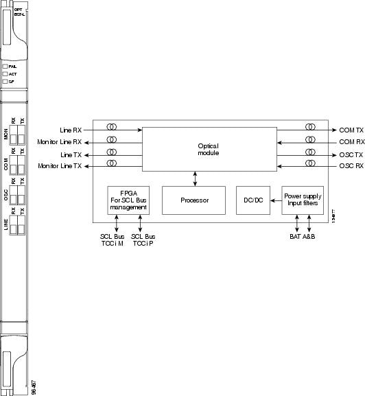
Figure 2 OPT-BST Optical Module Functional Diagram
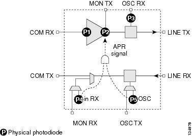
Power Monitoring
Physical photodiodes P1, P2, P3, P4, and P5 monitor the power for the OPT-BST-L card. The returned power level values are calibrated to the ports as shown in Table 1.
Card Level Indicators
The OPT-BST-L card has three card-level LED indicators described in Table 2.
Port-Level Indicators
You can find the status of the card ports using the LCD screen on the ONS 15454 ANSI fan-tray assembly. Use the LCD to view the status of any port or card slot; the screen displays the number and severity of alarms for a given port or slot.
The OPT-BST-L amplifier has eight optical ports located on the faceplate:
•MON RX is the output monitor port (receive section).
•MON TX is the output monitor port.
•COM RX is the input signal port.
•LINE TX is the output signal port.
•LINE RX is the input signal port (receive section).
•COM TX is the output signal port (receive section).
•OSC RX is the OSC add input port.
•OSC TX is the OSC drop output port.
OPT-BST-L Card Specifications
The OPT-BST-L amplifier card has the following specifications:
•Optical characteristics:
–Total operating wavelength range: 1570.0 to 1605.0 nm
–Gain ripple (peak to valley): 1.5 dB
–Gain range: 8 to 20 dB with programmable gain tilt
–Extended gain range: 20 to 27 dB with gain tilt uncontrolled
–Gain and power regulation over/undershoot: 0.5 dB
–Limited maximum output power: 10 dBm
–Maximum output power (with full channel load): 17 dB
–Minimum output power (with one channel): -10 dBm
–Input power (Pin) range at full channel load: -10 to 9 dBm
–Input power (Pin) range at single channel load: -37 to -18 dBm
–Noise figure at G3 20 dB = 7.5 dB
–Insertion Loss (Line RX to OSC TX): 0.3 to 1.8 dB
–Insertion Loss (Line RX to COM TX): 0.3 to 1.0 dB
–Insertion Loss (OSC RX to LINE TX): 0.3 to 1.3 dB
–Optical connectors: LC-UPC/2
•Environmental
–Operating temperature:
C-Temp: -5 to +55 degrees Celsius (+23 to +131 degrees Fahrenheit)
–Operating humidity: 5 to 85 percent, noncondensing
•Dimensions
–Height: 12.65 in. (332 mm)
–Width: 0.92 in. (24 mm)
–Depth: 9.00 in. (240 mm)
Install the OPT-BST-L Card
Warning Class I (CDRH) and Class 1M (IEC) laser products. Statement 1055
Warning Invisible laser radiation may be emitted from disconnected fibers or connectors. Do not stare into beams or view directly with optical instruments. Statement 272
Caution Do not install the DWDM cards until you are directed to do so during DWDM node turnup.
Note If protective clips are installed on the card connectors, remove the clips before installing the cards.
Note If you install a card incorrectly, the FAIL LED flashes continuously.
Note The automatic node setup (ANS) feature in the node begins to determine what kind of site you are installing as soon as you install cards. Automatic power control (APC) is enabled after ANS initializes and after a channel has been provisioned. To provision a DWDM channel, see the Cisco ONS 15454 DWDM Procedure Guide. For more information about amplifier power control, see the Cisco ONS 15454 DWDM Reference Manual .
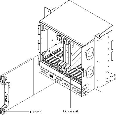
Figure 3 shows general card installation.
Figure 3 Installing a Card in the Cisco ONS 15454 SONET (ANSI) Shelf Assembly
Install OPT-BST-L card in any open east and west pair of slots.
Step 1 Plan your node installation or consult the site plan. As soon as you begin installing cards, ANS determines what kind of site to set up based on the following parameters:
•Hub site—Two 32DMX-O and two 32MUX-O cards are provisioned but no AD-xC or AD-xB cards are provisioned
•Terminal—One 32DMX-O and one 32MUX-O card are provisioned, and no AD-xC or AD-xB cards are provisioned
•Line site—Only one OPT-PRE, OPT-BST or OPT-BST-L is provisioned per line direction. (Up to two OPT-PRE, two OPT-BST-L, and two OPT-AMP-L cards can be provisioned in the same shelf.)
•OADM site—At least 1 AD-xC or AD-xB is provisioned and no 32DMX-O or 32MUX-O cards are provisioned
•Unknown—Provisioned cards do not follow any of the previously listed categories.
Step 2 Open the card latches/ejectors.
Step 3 Use the latches/ejectors to firmly slide the OPT-BST-L card along the guide rails until the card plugs into the receptacle at the back of the slot.
Step 4 Install the card in any open east and west pair of slots. OPT-BST-L cards are often installed in Slots 1 to 6 and 12 to 17.
Step 5 Verify that the card is inserted correctly and close the latches/ejectors on the card.
Note It is possible to close the latches/ejectors when the card is not completely plugged into the chassis. Ensure that you cannot insert the card any further.
The following LED activity will occur:
•The FAIL LED turns on for approximately 35 seconds. During this time, the ACT LED will cycle through various states, and then extinguish.
•The FAIL LED blinks for approximately 40 seconds.
•All LEDs turn on and then turn off within 5 seconds.
•If new software is being downloaded to the card, the ACT and SF LEDs blink from 20 seconds to 5 minutes, depending on the card type.
•The ACT LED turns on.
Step 6 The signal fail (SF) LED might persist until all card ports connect to their far-end counterparts and a signal is present.If the card does not boot up properly, or the LED activity does not mimic Step 5 check the following:
•When a physical card type does not match the type of card provisioned for that slot in CTC, the card might not boot. If a DWDM card does not boot, open CTC and ensure that the slot is not provisioned for a different card type before assuming the card is faulty.
•If the red FAIL LED does not turn on, check the power.
•If you insert a card into a slot provisioned for a different card, all LEDS turn off.
•If the red FAIL LED is on continuously or the LEDs behave erratically, the card is not installed properly. Remove the card and repeat steps 2 to 5.
Note Refer to the Cisco ONS 15454 DWDM Procedure Guide for fibering and provisioning instructions.
Related Documentation
•Cisco ONS 15454 DWDM Reference Manual
•Cisco ONS 15454 DWDM Procedure Guide
•Cisco ONS 15454 DWDM Troubleshooting Guide
•Cisco MetroPlanner DWDM Operations Guide
Obtaining Documentation and Submitting a Service Request
For information on obtaining documentation, submitting a service request, and gathering additional information, see the monthly What's New in Cisco Product Documentation, which also lists all new and revised Cisco technical documentation, at:
http://www.cisco.com/en/US/docs/general/whatsnew/whatsnew.html
Subscribe to the What's New in Cisco Product Documentation as a Really Simple Syndication (RSS) feed and set content to be delivered directly to your desktop using a reader application. The RSS feeds are a free service and Cisco currently supports RSS Version 2.0.
This document is to be used in conjunction with the documents listed in the "Related Documentation" section
© 2005 Cisco Systems, Inc. All rights reserved.
Printed in the USA on recycled paper containing 10% postconsumer waste.