Installing the Cisco ONS 15454 SONET/SDH FC_MR-4 Card
Available Languages
Table Of Contents
Installing Cisco ONS 15454 SONET/SDH
FC_MR-4 CardsProcedure: Install the FC_MR-4 Card
Procedure: Verify Turn Up of the FC_MR-4 Card
Obtaining Documentation and Submitting a Service Request
Installing Cisco ONS 15454 SONET/SDH
FC_MR-4 Cards
Product Name: 15454-ML-4FC=
This document lists regulatory requirements and describes installation procedures for the Cisco ONS 15454/ONS 15454 SDH FC_MR-4 card. It also contains removal instructions and technical specifications. Use this document in conjunction with the Cisco ONS 15454 SDH Reference Manual, the Cisco ONS 15454 SDH Procedure Guide, the Cisco ONS 15454 Reference Manual, and the Cisco ONS 15454 Procedure Guide.
This document contains the following sections:
•
"FC_MR-4 Card Description" section
•
•
•
This document contains the following procedures:
•
•
FC_MR-4 Card Description

Warning
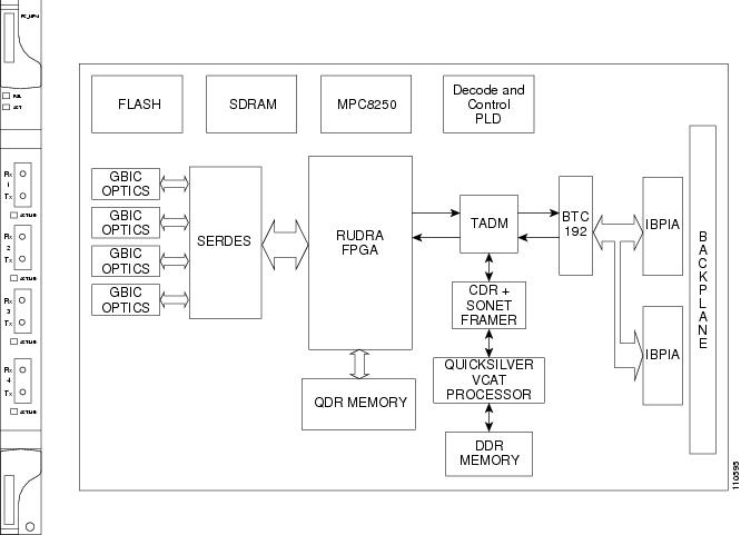
The FC_MR-4 (Fibre Channel 4-port) card uses pluggable Gigabit Interface Converters (GBICs) to transport non-SONET/SDH-framed, block-coded protocols over SONET/SDH in virtually concatenated or contiguously concatenated payloads. The FC_MR-4 can transport Fibre Channel over SONET/SDH using Fibre-Channel client interfaces and allows transport of one of the following at a time:
•
•
•
•
In Software Release 4.6, only two of the four ports can be active at one time.
Figure 0-1 shows the FC_MR-4 faceplate and block diagram.
Figure 0-1 FC_MR-4 Faceplate and Block Diagram
FC_MR-4 Card-Level Indicators
Table 0-1 describes the two card-level LEDs on the FC_MR-4 card.
FC_MR-4 Port-Level Indicators
Each FC_MR-4 port has a corresponding ACT/LNK LED. The ACT/LNK LED is solid green if the port is available to carry traffic, is provisioned as in-service, and in the active mode. The ACT/LNK LED is flashing green if the port is carrying traffic. The ACT/LNK LED is steady amber if the port is not enabled and the link is connected, or if the port is enabled and the link is connected but there is a SONET transport error. The ACT/LNK LED is unlit if there is no link.
You can find the status of the card ports using the LCD screen on the ONS 15454 fan-tray assembly. Use the LCD to view the status of any port or card slot; the screen displays the number and severity of alarms for a given port or slot. Refer to the Cisco ONS 15454 Troubleshooting Guide for a complete description of the alarm messages.
FC_MR-4 Card Specifications
The FC_MR-4 card has the following specifications:
•
–
C-Temp (15454-E100T): -5 to +55 degrees Celsius (23 to 131 degrees Fahrenheit)
–
–
•
–
–
–
–
•
–
Installation Procedures
Use this section if you are installing the FC_MR-4 card for the first time. After you become familiar with ONS 15454 SONET/SDH card installation and boot up, use this section as a reference. For information about fiber optic cable installation, see the Cisco ONS 15454 SDH Reference Manual, the Cisco ONS 15454 SDH Procedure Guide, the Cisco ONS 15454 Reference Manual, or the Cisco ONS 15454 Procedure Guide.
Warning

Caution
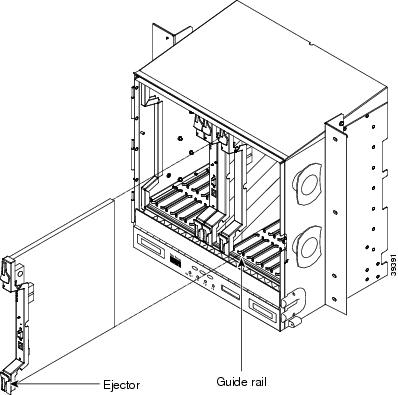
FC_MR-4 cards have electrical plugs that plug into electrical connectors on the shelf assembly backplane. When the ejectors are fully closed, the card plugs into the shelf assembly backplane. Figure 2 shows general card installation. The example shows the installation in an ONS 15454. The procedure in an ONS 15454 SDH is identical.
Figure 2 Installing a card in an ONS 15454
Procedure: Install the FC_MR-4 Card
Step 1
Step 2
Step 3
Procedure: Verify Turn Up of the FC_MR-4 Card
Follow the steps in this section to verify card turn up. If one or more of the Cisco Transport Controller (CTC) software screen conditions according to this procedure are not met, reinstall the card. Replace the unit if the faulty state persists.
Step 1
Step 2
•
•
•
•

Note
Note
Step 3
Step 4
Related Documentation
•
•
•
•
•
•
Obtaining Documentation and Submitting a Service Request
For information on obtaining documentation, submitting a service request, and gathering additional information, see the monthly What's New in Cisco Product Documentation, which also lists all new and revised Cisco technical documentation, at:
http://www.cisco.com/en/US/docs/general/whatsnew/whatsnew.html
Subscribe to the What's New in Cisco Product Documentation as a Really Simple Syndication (RSS) feed and set content to be delivered directly to your desktop using a reader application. The RSS feeds are a free service and Cisco currently supports RSS version 2.0.
 Feedback
Contact Cisco
- Open a Support Case

- (Requires a Cisco Service Contract)