Installing Cisco ONS 15454 SONET/SDH XC-VXC-10G Cards
Available Languages
Table Of Contents
Installing Cisco ONS 15454 SONET/SDH XC-VXC-10G Cards
XC-VXC-10G Cross-Connect Card Description
XC-VXC-10G Card-Level Indicators
XC-VXC-10G Card Specifications
Upgrading from an XC10G or XC-VXL-10G Card to the XC-VXC-10G Card
Obtaining Documentation and Submitting a Service Request
Installing Cisco ONS 15454 SONET/SDH XC-VXC-10G Cards
Product Name: 15454-XC-VXC-10G (SONET) and 15454E-XC-VXC-10G (SDH)
This document contains a description of XC-VXC-10G card features, installation procedures, and technical specifications. Use this document in conjunction with the ONS 15454 Procedure Guide, Cisco ONS 15454 Reference Manual, and ONS 15454 Troubleshooting Guide when working with XC-VXC-10G cards in a SONET platform. Use the ONS 15454 SDH Procedure Guide, Cisco ONS 15454 SDH Reference Manual, and ONS 15454 SDH Troubleshooting Guide when working with them in an SDH platform.
This document contains the following sections:
•
"XC-VXC-10G Cross-Connect Card Description" section
•
•
•
•
•

Note
XC-VXC-10G Cross-Connect Card Description
The XC-VXC-10G card establishes connections at the STS and VT levels (SONET) or VC-4, VC-3, VC-12, and VC-11 levels (SDH). For SONET, the XC-VXC-10G provides STS-192 capacity to Slots 5, 6, 12, and 13, and STS-48 capacity to Slots 1 to 4 and 14 to 17. For SDH, it provides STM-64 capacity to Slots 5, 6, 12, and 13, and STM-16 capacity to Slots 1 to 4 and 14 to 17. Any STS-1/VC-4 on any port can be connected to any other port, meaning that the STS/VC cross-connections are nonblocking.
For SONET, the XC-VXC-10G card can be configured to support either VT1.5 or VT2 grooming, or mixed (VT1.5 and VT2) grooming. For SDH, it can be configured to support either VC-12 or VC-11 grooming, or mixed (VC-12 and VC-11) grooming.
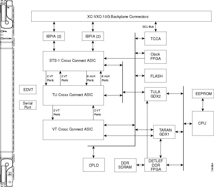
Figure 1 shows the XC-VXC-10G faceplate and block diagram.
Figure 1 XC-VXC-10G Faceplate and Block Diagram
XC-VXC-10G Functionality
The functionality of the XC-VXC-10G card can be divided into SONET and SDH.
SONET Functionality
The XC-VXC-10G card manages up to 1152 bidirectional high-order STS-1 ports. In addition, it is able to simultaneously manage one of the following low-order VT cross-connect arrangements:
•
•
•
The TCC2/TCC2P card assigns bandwidth to each slot on a per STS-1, per VT1.5, or per VT2 basis. The switch matrices are fully crosspoint and broadcast supporting.
At the STS level (high-order cross-connect), the XC-VXC-10G is always non-blocking (any STS-1 from the system can be cross-connected to any other STS-1 without limitation up to 1152 bidirectional STS-1 ports (576 STS-1 cross-connects).
In addition, for "mixed" VT1.5 and VT2 grooming, 50% of the available VT resources (ports) are allocated to each VT circuit type. The following three modes are supported (only one mode is available at a time):
•
•
•
The XC-VXC-10G card provides:
•
•
•
•
•
•
•
•
•
Note
The XC-VXC-10G supports errorless side switches (switching from one XC-VXC-10G on one side of the shelf to the other XC-VXC-10G on the other side of the shelf) when the switch is initiated through software and the shelf is equipped with TCC2/TCC2P cards.
Cross-connect and provisioning information is established through the user interface on the TCC2/TCC2P card. In turn, the TCC2/TCC2P card establishes the proper internal cross-connect information and relays the setup information to the XC-VXC-10G card so that the proper cross-connection is established within the system.
The XC-VXC-10G card is deployed in Slots 8 or 10. Upgrading a system to an XC-VXC-10G from an earlier cross-connect module type is performed in-service, with hitless operation (less than 50-ms impact to any traffic). The XC-VXC-10G can be used with either the standard ANSI shelf assembly
(15454-SA- ANSI) or high-density shelf assembly (15454-SA-HD).
Caution
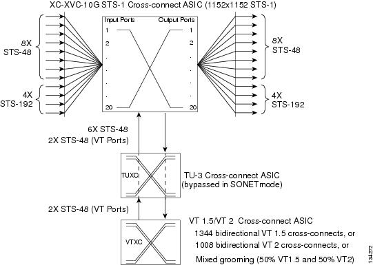
Figure 2 shows the XC-VXC-10G cross-connect matrix.
Figure 2 XC-VXC-10G Cross-Connect Matrix
VT Mapping
The VT structure is designed to transport and switch payloads below the DS-3 rate. The ONS 15454 performs VT mapping according to Telcordia GR-253-CORE standards. Table 1 shows the VT numbering scheme for the ONS 15454 as it relates to the Telcordia standard.
XC-VXC-10G Hosting DS3XM-6 or DS3XM-12
A DS3XM card can demultiplex (map down to a lower rate) M13-mapped DS-3 signals into 28 DS-1s that are then mapped to VT1.5 payloads. The VT1.5s can then be cross-connected by the XC-VXC-10G card. The XC-VXC-10G card can host a maximum of 1344 bidirectional VT1.5s.
SDH Functionality
The XC-VXC-10G card manages up to 192 bidirectional VC-4 cross-connects, 192 VC-3 bidirectional cross-connects, 1008 VC-12 bidirectional cross-connects, or 1344 VC-11 bidirectional cross-connects. The TCC2/TCC2P card assigns bandwidth to each slot on a per-STM-1 basis.
The XC-VXC-10G card provides the following:
•
•
•
•
•
•
•
•
•
•
•
–
–
–
Caution
The XC-VXC-10G supports errorless side switches (switching from one XC-VXC-10G on one side of the shelf to the other XC-VXC-10G on the other side of the shelf) at the VC-4 circuit level when the switch is initiated through software and the shelf is equipped with TCC2/TCC2P cards.
Note
Note
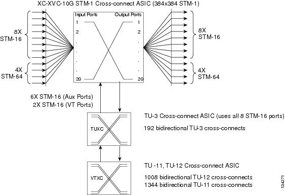
Figure 3 shows the XC-VXC-10G cross-connect matrix.
Figure 3 XC-VXC-10G Cross-Connect Matrix
XC-VXC-10G Card-Level Indicators
Table 2 describes the two card-level LEDs on the XC-VXC-10G faceplate.
XC-VXC-10G Compatibility
For SONET, the XC-VXC-10G card supports the same features as the XC10G card. Either the XC-VXC-10G or XC10G cards are required for OC-192, OC3-8, and OC12-4 operation and OC-48 AS operation. For SDH, The XC-VXC-10G card supports the same features as the XC-VXL-10G and XC-VXL-2.5G cards. The XC-VXC-10G cards support STM-64 operation.
If you are using Ethernet cards, the E1000-2-G or the E100T-G must be used when the XC-VXC-10G cross-connect cards are in use.
XC-VXC-10G Card Specifications
The XC-XVC-10G card has the following specifications:
•
–
I-Temp (15454-XC-VXC-10G-T): -40 to 149 degrees Fahrenheit (-40 to +65 degrees Celsius)
–
–
•
–
–
–
–
•
Install the XC-VXC-10G Cards
Use this section if you are installing the XC-VXC-10G cards for the first time. After you become familiar with ONS 15454 card installation and boot up, use this section as a reference.
Warning
Caution
Caution
Note
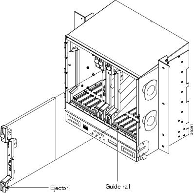
XC-VXC-10G cards have electrical plugs that plug into electrical connectors on the shelf assembly backplane. When the ejectors are fully closed, the card plugs into the shelf assembly backplane. Figure 4 shows general card installation.
Figure 4 Installing a Card in an ONS 15454
Note
This is not the procedure to use when upgrading from XC10G (for SONET) or XC-VXL-10G (for SDH) to XC-VXC-10G cards. If you are performing an XC10G or XC-VXL-10G to a XC-VXC-10G upgrade, see the "Upgrading from an XC10G or XC-VXL-10G Card to the XC-VXC-10G Card" section.
Step 1
Step 2
Step 3
Step 4
Step 5
Note
Step 6
Step 7

Tip
Upgrading from an XC10G or XC-VXL-10G Card to the XC-VXC-10G Card
This section explains how to upgrade dual XC10G cards (SONET) or dual XC-VXL-10G cards (SDH) with dual XC-VXC-10G cards in an ONS 15454 with live traffic. Because the upgrade causes a switch of less than 50 ms, the procedure is non-service affecting.
Upgrading XC10G cards or XC-VXL-10G cards to XC-VXC-10G cards requires that the ONS 15454 be running CTC Release 6.0 or later. Two XC10G cards (for SONET) or two XC-VXL-10G cards (for SDH) must be installed in the ONS 15454, and two XC-VXC-10G cards must be available for installation.
Note
Step 1
a.
b.
c.
In a BLSR, place a lockout on the East and West cards of the nodes adjacent to the XC10G or XC-VXL-10G switch node; for example, to switch the XC10G or XC-VXL-10G on Node B, place the lockout on the West card of Node A and on the East card of Node C. No lockout is necessary on Node B. Before the lockout is set, verify that the BLSR is not switched. If a lockout is set while the BLSR is switched, traffic can be lost.
<------East [Node A] West------East [Node B] West------East [Node C] West------>
In a 1+1 protection scheme, place a lockout on the protect card and verify.
Step 2
Note
Step 3
a.
b.
c.
d.
The fail LED above the ACT/STBY LED becomes red, blinks for several seconds, and turns off. The ACT/STBY LED turns amber and stays lit.
e.
Step 4
Step 5
Step 6
Note
Step 7
a.
b.
c.
d.
e.
The upgrade is complete when the second XC-VXC-10G card boots up and becomes the standby XC-VXC-10G.
Step 8
Related Documentation
•
•
Obtaining Documentation and Submitting a Service Request
For information on obtaining documentation, submitting a service request, and gathering additional information, see the monthly What's New in Cisco Product Documentation, which also lists all new and revised Cisco technical documentation, at:
Subscribe to the What's New in Cisco Product Documentation as a Really Simple Syndication (RSS) feed and set content to be delivered directly to your desktop using a reader application. The RSS feeds are a free service and Cisco currently supports RSS version 2.0.
This document is to be used in conjunction with the documents listed in the "Related Documentation" section.
Cisco and the Cisco logo are trademarks or registered trademarks of Cisco and/or its affiliates in the U.S. and other countries. To view a list of Cisco trademarks, go to this URL: www.cisco.com/go/trademarks. Third-party trademarks mentioned are the property of their respective owners. The use of the word partner does not imply a partnership relationship between Cisco and any other company. (1110R)
Any Internet Protocol (IP) addresses used in this document are not intended to be actual addresses. Any examples, command display output, and figures included in the document are shown for illustrative purposes only. Any use of actual IP addresses in illustrative content is unintentional and coincidental.
© 2004 Cisco Systems, Inc. All rights reserved.

 Feedback
Contact Cisco
- Open a Support Case

- (Requires a Cisco Service Contract)