Installing the Electrical Interface Assemblies in the ONS 15454
Available Languages
Table Of Contents
Installing Electrical Interface Assemblies in the Cisco ONS 15454
EIA Naming and Shelf Assembly Compatibility
ONS 15454 Backplane Description
Prepare the Backplane for EIA Installation
Install the High-Density BNC EIA
Verify the Electrical Connection
Installing Electrical Interface Assemblies in the Cisco ONS 15454
Product Numbers: 15454-EIA-BNC-A24=, 15454-EIA-BNC-B24=, 15454-EIA-BNC-A48=, 15454-EIA-BNC-B48=, 15454-EIA-SMB-A84=, 15454-EIA-SMB-B84=, 15454-EIA-AMP-A84=, 15454-EIA-AMP-B84=, 15454-EIA-1BNCA24=, 15454-EIA-1BNCB24=, 15454-EIA-1BNCA48=, 15454-EIA-1BNCB48=, 15454-EIA-1SMBA84=, 15454-EIA-1SMBB84=, 15454-EIA-1AMPA84=, 15454-EIA-1AMPB84=This document describes how to install Electrical Interface Assemblies (EIAs) for the Cisco ONS 15454. EIAs are pre-installed on the ONS 15454 when ordered with the system. EIAs host a special card that provides coaxial cable connection points (SMB or BNC) for the DS-3 or EC-1 cards. EIAs also host twisted pair wire-wrap adapters for SMB connectors or, for the DS-1 card, AMP Champ connectors. EIAs have a special backplane cover with cutouts over the cable connectors.
Use this document in conjunction with the Cisco ONS 15454 Procedure Guide and the Cisco ONS 15454 Reference Manual when working with EIAs or any other system components.
This document contains the following sections:
•
EIA Naming and Shelf Assembly Compatibility
•
•
EIA Naming and Shelf Assembly Compatibility
The procedures in this document refer to A-side and B-side EIAs. As you face the rear of the ONS 15454 shelf assembly, the right-hand side is considered the A side and the left-hand side is the B side. Table 1 shows the EIA types supported by both the 15454-SA-ANSI and the 15454-SA-HD shelf assemblies.
Table 1 EIA Configurations Compatible with the 15454-SA-ANSI and the 15454-SA-HD
BNC
DS-3 DS3XM-6 EC-1
24 pairs of BNC connectors
Slot 2
Slot 4
15454-EIA-1BNCA24=
24 pairs of BNC connectors
Slot 14
Slot 16
15454-EIA-1BNCB24=
High- Density BNC
DS-3 DS3XM-6 EC-1
48 pairs of BNC connectors
Slot 1
Slot 2
Slot 4
Slot 5
15454-EIA-1BNCA48=
48 pairs of BNC connectors
Slot 13
Slot 14
Slot 16
Slot 17
15454-EIA-1BNCB48=
SMB
DS-1
DS-3
EC-1
DS3XM-6
84 pairs of SMB connectors
Slot 1
Slot 2
Slot 3
Slot 4
Slot 5
Slot 6
15454-EIA-1SMBA84=
84 pairs of SMB connectors
Slot 12
Slot 13
Slot 14
Slot 15
Slot 16
Slot 17
15454-EIA-1SMBB84=
AMP Champ
DS-1
6 AMP Champ connectors
Slot 1
Slot 2
Slot 3
Slot 4
Slot 5
Slot 6
15454-EIA-1AMPA84=
6 AMP Champ connectors
Slot 12
Slot 13
Slot 14
Slot 15
Slot 16
Slot 17
15454-EIA-1AMPB84=
UBIC1
DS-1
DS-3
DS3X
EC-1
E-1
16 UBIC connectors
Slot 1
Slot 2
Slot 3
Slot 4
15454-EIA-UBICH-A=
16 UBIC connectors
Slot 14
Slot 15
Slot 16
Slot 17
15454-EIA-UBICH-B=
1 The UBIC EIA Type is compatible only with 15454-SA-HD.
ONS 15454 Backplane Description
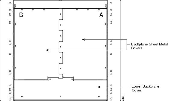
Before installing EIAs, familiarize yourself with the rear of the ONS 15454. Figure 1 shows the location of the lower backplane cover and the backplane sheet metal covers. The sheet metal covers and EIAs attach to the shelf assembly using nine perimeter screws. Five screws hold the lower backplane cover in place.
Figure 1 ONS 15454 Rear View (with Sheet Metal Covers Attached)
Prepare the Backplane for EIA Installation
Before installing the EIA(s), you must prepare the backplane for installation. If an EIA has not been installed, you need to remove the backplane covers to expose the EIA backplane-mating connectors.
Step 1
Step 2
Step 3
Step 4
Attach the backplane sheet metal cover(s) whenever EIA(s) are not installed. Figure 2 shows how to remove a sheet metal cover.
Figure 2 Removing a sheet metal cover

Installing EIAs
Except for an additional step required to install the AMP Champ EIA, the installation procedure is identical for all the EIA types. To install an EIA, you remove the lower backplane cover, remove the backplane sheet metal covers, plug the EIA card into the mating connectors, attach the EIA cover panel, and secure the EIA to the ONS 15454 using nine perimeter screws. To install the AMP Champ EIA, you must also attach the fastening plate at the bottom of the connector row. This section describes the installation procedures for each EIA.
You will need a calibrated torque driver set to 9 in-lbs to perform the installation procedures.

Caution

Note
Note
Inspect the EIA Cards
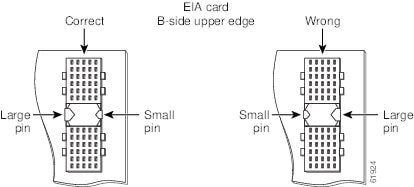
Before installing an EIA card, you must inspect the EIA card to determine that the connectors are not rotated from their original position. A card with rotated connectors can be installed, but may cause problems during turn up. If you must use more than normal pressure to seat the card, you should inspect it for rotated connectors.
Note
Step 1
Step 2
If the connectors are rotated, contact the Cisco Technical Assistance Center (TAC) at 1-877-323-7368 to open a Return Material Authorization and Fault Symptom Report (RMA).
Figure 3 A-Side Correct and Incorrect Connector Position
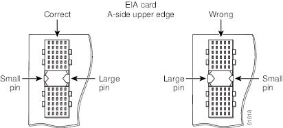
Figure 4 B-Side Correct and Incorrect Connector Position
Install the BNC EIA
The BNC backplane is designed for use with DS-3 (including DS3XM-6) and EC-1 cards. The EIA A side hosts 24 pairs of BNC connectors. The first 12 pairs of BNC connectors map to Slot 2 on the shelf assembly and correspond to Ports 1 through 12 of a 12-port card. The second 12 BNC connector pairs map to Slot 4 on the shelf assembly and correspond to Ports 1 through 12 of a 12 port card.
The EIA B side provides an additional 24 pairs of BNC connectors. The first 12 BNC connector pairs correspond to Ports 1 through 12 of a 12-port card and map to Slot 14 on the shelf assembly. The second 12 BNC connector pairs correspond to Ports 1 through 12 of a 12-port card and map to Slot 16 on the shelf assembly. The BNC connector pairs are marked "Tx" and "Rx" to indicate the transmit and receive cables for each port.
Install the BNC EIA(s) after removing the backplane sheet metal covers or existing EIA(s). See the "Removing EIAs" section if applicable.
Step 1
Step 2
Step 3
Step 4
Step 5
Step 6
For more information about the BNC EIA, refer to the Cisco ONS 15454 Reference Manual.
Figure 5 shows BNC EIA installation.
Figure 5 Installing the BNC EIA
Install the High-Density BNC EIA
The High-Density BNC backplane is designed for use with DS-3 (including DS3XM-6) and EC-1 cards. The EIA A side hosts 48 pairs of BNC connectors. Each column of connector pairs is numbered and corresponds to the slot of the same number. The first column (12 pairs) of BNC connectors corresponds to Slot 1 on the shelf assembly, the second column to Slot 2, the third column to Slot 4 and the fourth column to Slot 5. The rows of connectors correspond to Ports 1 through 12 of a 12-port card.
The EIA B side provides an additional 48 pairs of BNC connectors. The first column (12 pairs) of BNC connectors corresponds to Slot 13 on the shelf assembly, the second column to Slot 14, the third column to Slot 16 and the fourth column to Slot 17. The rows of connectors correspond to Ports 1 through 12 of a 12-port card. The BNC connector pairs are marked "Tx" and "Rx" to indicate transmit and receive cables for each port.
Install the BNC EIA(s) after either removing the backplane sheet metal covers or existing EIA(s). See the "Removing EIAs" section if applicable.
Step 1
Step 2
Step 3
Step 4
Step 5
Step 6
For information about connecting to the High-Density BNC EIA, refer to the Cisco ONS Procedure Guide.
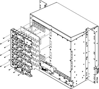
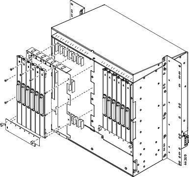
Figure 6 shows High-Density BNC EIA installation.
Figure 6 Installing the High-Density BNC EIA
Install the SMB EIA
The SMB backplane is designed for use with DS-1, DS-3 (including DS3XM-6), or EC-1 cards. The EIA A side hosts 84 SMB connectors in six columns of 14 connectors. The A side columns are numbered
1 - 6 and correspond to Slots 1 - 6 on the shelf assembly. The EIA B side hosts an additional 84 SMB connectors in six columns of 14 connectors. The B side columns are numbered 12 - 17 and correspond to slots 12 - 17 on the shelf assembly. The connector rows are numbered 1 - 14 and correspond to the 14 ports on a DS-1 card. If you use a DS-3 or EC-1 card, only Ports 1 - 12 are active. If you use a DS3XM-6 card, only Ports 1 - 6 are active. The SMB connector pairs are marked "Tx" and "Rx" to indicate the transmit and receive cables for each port. If you use SMB connectors, you can install DS-1, DS-3, or EC-1 cards in any general purpose slot.If you are replacing or changing EIA(s), you must first remove the existing EIA. See the "Removing EIAs" section.
Step 1
Step 2
Caution
Step 3
Step 4
Step 5
Step 6
If you are using SMB EIAs to make DS-1 connections, you need the DS-1 electrical interface adapter, commonly referred to as a balun (P/N 15454-WW-14=).
For information about connecting to the SMB EIA, refer to the Cisco ONS 15454 Procedure Guide.
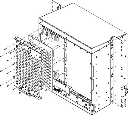
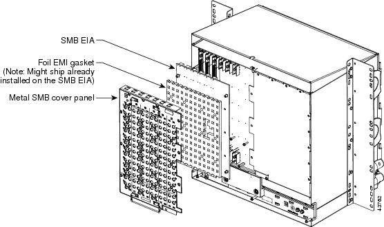
Figure 7 shows an SMB EIA installation.
Figure 7 Installing the SMB EIA
Install the AMP Champ EIA
The EIA A side hosts six AMP Champ connectors, one for each service card slot on that side of the backplane. The connectors are labeled 1 - 6 and correspond to Slots 1 - 6 on the shelf assembly. The EIA B side hosts six AMP Champ connectors, one for each service card slot on that side of the backplane. The connectors are labeled 12 - 17 and correspond to Slots 12 - 17 on the shelf assembly. Each AMP Champ connector on the backplane supports 14 DS-1 ports for a DS1-14 card, and each connector has 28 live pairs—one transmit pair and one receive pair—for each DS-1 port.
If you are replacing or changing EIA(s), you must first remove the existing EIA. See the "Removing EIAs" section.
Step 1
Step 2
Step 3
Step 4
Step 5
For more information about AMP Champ EIA(s), refer to the Cisco ONS 15454 Procedure Guide.
Figure 8 shows AMP Champ EIA installation.
Figure 8 Installing the AMP Champ EIA
Verify the Electrical Connection
After installing the EIAs you should verify that the ports are making an electrical connection. Cisco recommends that you use a DS-1 card to test all fourteen ports. As an alternative, you can use a DS-3 card to test the first twelve ports.
Step 1
Step 2
a.
b.
c.
Step 3
Step 4
Step 5
Step 6
Step 7
Removing EIAs
Step 1
Step 2
If you are removing an AMP Champ EIA, remove the fastening plate before proceeding. To remove the fastening plate, loosen the two thumbscrews.
Step 3
This document is to be used in conjunction with the Cisco ONS 15454 Procedure Guide.

 Feedback
Contact Cisco
- Open a Support Case

- (Requires a Cisco Service Contract)