Electrostatic Discharge and Grounding Guide for Cisco CPT and Cisco ONS Platforms
This document uses illustrations to explain the workflow that we recommend for grounding the Cisco CPT, Cisco ONS 15454 M2, ONS 15454 M6, NCS 2015, ONS 15454 ANSI, ONS 15454 ETSI, ONS 15310-MA ANSI, ONS 15310-MA ETSI, ONS 15310-CL ANSI, ONS 15600 ANSI, and ONS 15600 ETSI chassis. It also explains best practices to be followed to prevent electrostatic discharge (ESD) damage, which can occur when the equipment is improperly handled.
Electrostatic Discharge and Grounding Guide
The instructions in this document also applies to the Cisco ONS DWDM platform.
The following sections are included in this document:
Prerequisites
Before locating and grounding any chassis, you must complete the following prerequisites:
Moving the Shelf
Perform the following steps before moving the shelf to the new site.
 Note |
It is recommended to back up the database before moving the shelf. |
-
Remove the standby control card from the node.
-
Switch off the power to the shelf.
-
Remove the active control card from the node.
-
Move the node to the desired location.
-
Insert the standby control card first in the active slot to boot up the shelf.
-
When the shelf is booted up and traffic is running, the Protection Unit Not Available (PROTNA) alarm is raised.
-
Insert the previously active control card in the standby slot to clear the PROTNA alarm.
Preparing Your Location
This section illustrates how the building that houses the chassis must be properly grounded to the earth ground.
 Warning |
This product requires short-circuit (overcurrent) protection to be provided as part of the building installation. Install only in accordance with national and local wiring regulations. Statement 1045. |
Warning |
A readily accessible two-poled disconnect device must be incorporated in the fixed wiring. Statement 1022. |
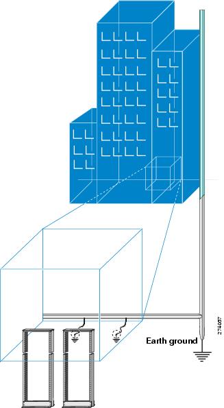
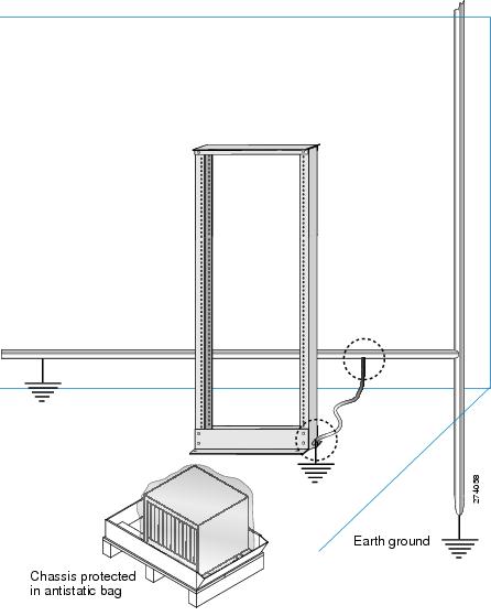
Preparing the Rack Room
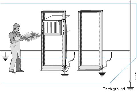
This section explains how the rack enclosures must be properly connected to the building earth ground. It also illustrates how to keep the chassis in a sealed anti-static bag until you are ready to install it.
Warning |
Before performing any of the following procedures, ensure that power is removed from the DC circuit. Statement 1003. |
Preparing Yourself
This section illustrates how to prepare yourself before removing the chassis from the sealed anti-static bag. The figure below, illustrates how to cuff the ESD strap around the wrist and the ground cord that connects the cuff to the ground. ESD wrist straps are the primary means of controlling static charge on personnel.
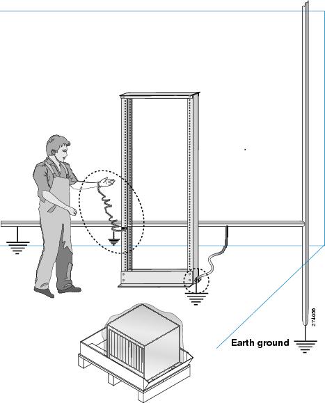
The following figure, illustrates how you must be properly grounded before handling the chassis.
Locating and Grounding the Chassis
This section explains how to locate and ground the following Cisco ONS chassis:
Warning |
This equipment is intended to be grounded. Ensure that the host is connected to earth ground during normal use. Statement 39. |
Warning |
Use copper conductors only. Statement 1025. |
Warning |
When installing or replacing the unit, the ground connection must always be made first and disconnected last. Statement 1046. |
Note |
A #6 AWG cable or a 1 inch wide flat copper braid (with minimum total strands count of 1050 x 36 AWG or 260 x 36 AWG) is mandatory to install the Cisco ONS 15454 M2, ONS 15454 M6, NCS 2015, ONS 15454 ANSI, ONS 15454 ETSI, ONS 15310-MA ANSI, ONS 15310-MA ETSI, ONS 15310-CL ANSI, ONS 15600 ANSI, and ONS 15600 ETSI chassis. |
Locating and Grounding the CPT 50 Shelf
Before locating and grounding the CPT 50 shelf, you must complete the prerequisites mentioned in Prerequisites. To locate the ground point and attach a ground cable to the CPT 50 shelf:
SUMMARY STEPS
- Verify that the office ground cable is connected to the top of the bay and the office ground, according to local site practice.
- Remove any paint and other non-conductive coatings from the surfaces between the shelf ground and bay frame ground point. Clean the mating surfaces and apply appropriate antioxidant compound to the bare conductors.
- Attach one end of the shelf ground cable (#8 AWG cable) to the ground point (rear or lateral) on the chassis using the specified dual-hole lug connector. (See diagrams 1 and 2 in the figure below .)
- Tighten the lug using the M4 pan-head screw to torque value of 11.5 in-lbs (1.3 N-m).
- Attach the other end of the shelf ground cable to the bay frame using a dual-hole lug connector according to the equipment bay frame specifications. (See diagram 3 of the figure below.)
DETAILED STEPS
| Step 1 |
Verify that the office ground cable is connected to the top of the bay and the office ground, according to local site practice.
|
||||||
| Step 2 |
Remove any paint and other non-conductive coatings from the surfaces between the shelf ground and bay frame ground point. Clean the mating surfaces and apply appropriate antioxidant compound to the bare conductors. |
||||||
| Step 3 |
Attach one end of the shelf ground cable (#8 AWG cable) to the ground point (rear or lateral) on the chassis using the specified dual-hole lug connector. (See diagrams 1 and 2 in the figure below .) |
||||||
| Step 4 |
Tighten the lug using the M4 pan-head screw to torque value of 11.5 in-lbs (1.3 N-m).
|
||||||
| Step 5 |
Attach the other end of the shelf ground cable to the bay frame using a dual-hole lug connector according to the equipment bay frame specifications. (See diagram 3 of the figure below.) 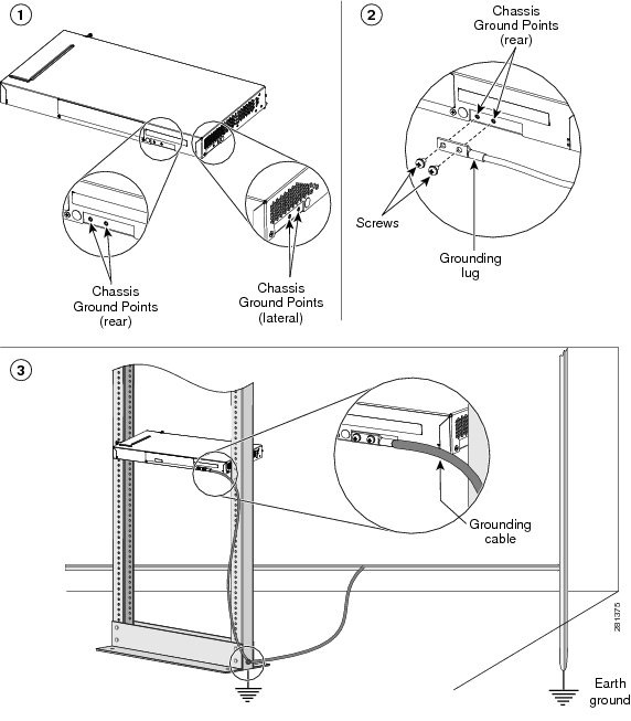 |
Locating and Grounding the Cisco ONS 15454 M2 Chassis
Before locating and grounding the Cisco ONS 15454 M2 chassis, you must complete the prerequisites mentioned in Prerequisites. To locate the ground point and attach a ground cable to the Cisco ONS 15454 M2 chassis:
SUMMARY STEPS
- Verify that the office ground cable is connected to the top of the bay and the office ground, according to local site practice.
- Remove any paint and other non-conductive coatings from the surfaces between the chassis ground and bay frame ground point. Clean the mating surfaces and apply appropriate antioxidant compound to the bare conductors.
- Attach one end of the shelf ground cable (#6 AWG cable or 1 inch copper braid) to the ground point on the chassis using the specified dual-hole lug connector. (See diagrams 1 and 2 in the figure, below.)
- Attach the other end of the shelf ground cable to the bay frame using a dual-hole lug connector according to the equipment bay frame specifications. (See diagram 3 of the following figure.)
DETAILED STEPS
| Step 1 |
Verify that the office ground cable is connected to the top of the bay and the office ground, according to local site practice.
|
||||
| Step 2 |
Remove any paint and other non-conductive coatings from the surfaces between the chassis ground and bay frame ground point. Clean the mating surfaces and apply appropriate antioxidant compound to the bare conductors. |
||||
| Step 3 |
Attach one end of the shelf ground cable (#6 AWG cable or 1 inch copper braid) to the ground point on the chassis using the specified dual-hole lug connector. (See diagrams 1 and 2 in the figure, below.) |
||||
| Step 4 |
Attach the other end of the shelf ground cable to the bay frame using a dual-hole lug connector according to the equipment bay frame specifications. (See diagram 3 of the following figure.) 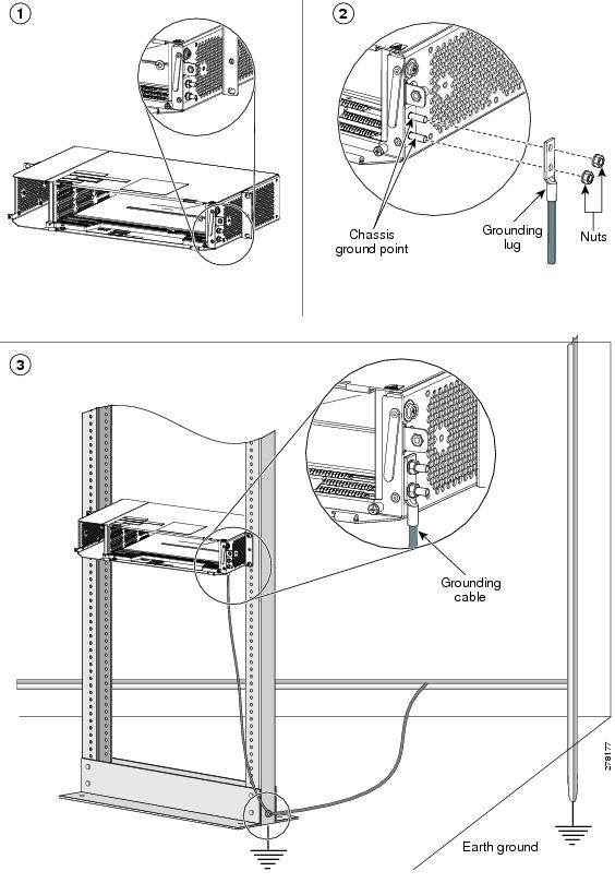 Stop. You have completed grounding the chassis. |
Locating and Grounding the Cisco ONS 15454 M6 Chassis
Before locating and grounding the Cisco ONS 15454 M6 chassis, you must complete the prerequisites mentioned in the Prerequisites section. To locate the ground point and attach a ground cable to the Cisco ONS 15454 M6 chassis:
SUMMARY STEPS
- Verify that the office ground cable is connected to the top of the bay and the office ground, according to local site practice.
- Remove any paint and other non-conductive coatings from the surfaces between the chassis ground and bay frame ground point. Clean the mating surfaces and apply appropriate antioxidant compound to the bare conductors.
- Attach one end of the shelf ground cable to the ground point on the chassis using the specified dual-hole lug connector. (See diagrams 1 and 2 in the figure, below.)
- Attach the other end of the shelf ground cable to the bay frame using a dual-hole lug connector according to equipment bay frame specifications. (See diagram 3 in the figure, below.)
DETAILED STEPS
| Step 1 |
Verify that the office ground cable is connected to the top of the bay and the office ground, according to local site practice.
|
||||
| Step 2 |
Remove any paint and other non-conductive coatings from the surfaces between the chassis ground and bay frame ground point. Clean the mating surfaces and apply appropriate antioxidant compound to the bare conductors. |
||||
| Step 3 |
Attach one end of the shelf ground cable to the ground point on the chassis using the specified dual-hole lug connector. (See diagrams 1 and 2 in the figure, below.) |
||||
| Step 4 |
Attach the other end of the shelf ground cable to the bay frame using a dual-hole lug connector according to equipment bay frame specifications. (See diagram 3 in the figure, below.)  Stop. You have completed grounding the chassis. |
Locating and Grounding the Cisco NCS 2015 Chassis
Before locating and grounding the Cisco NCS 2015 chassis, you must complete the prerequisites mentioned in the Prerequisites section. To locate the ground point and attach a ground cable to the Cisco NCS 2015 chassis:
SUMMARY STEPS
- Verify that the office ground cable is connected to the top of the bay and the office ground, according to local site practice.
- Remove any paint and other non-conductive coatings from the surfaces between the chassis ground and bay frame ground point. Clean the mating surfaces and apply appropriate antioxidant compound to the bare conductors.
- Attach one end of the shelf ground cable to the ground point on the chassis using the specified dual-hole lug connector. (See diagrams 1 and 2 in the figure, below.)
- Attach the other end of the shelf ground cable to the bay frame using a dual-hole lug connector according to equipment bay frame specifications. (See diagram 3 in the figure, below.)
DETAILED STEPS
| Step 1 |
Verify that the office ground cable is connected to the top of the bay and the office ground, according to local site practice.
|
||||
| Step 2 |
Remove any paint and other non-conductive coatings from the surfaces between the chassis ground and bay frame ground point. Clean the mating surfaces and apply appropriate antioxidant compound to the bare conductors. |
||||
| Step 3 |
Attach one end of the shelf ground cable to the ground point on the chassis using the specified dual-hole lug connector. (See diagrams 1 and 2 in the figure, below.) |
||||
| Step 4 |
Attach the other end of the shelf ground cable to the bay frame using a dual-hole lug connector according to equipment bay frame specifications. (See diagram 3 in the figure, below.) 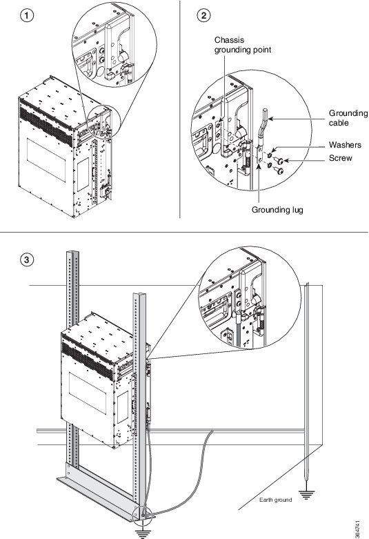 Stop. You have completed grounding the chassis. |
Locating and Grounding the Cisco ONS 15454 ANSI Chassis
Before locating and grounding the Cisco ONS 15454 ANSI chassis, you must complete the prerequisites mentioned in the Prerequisites section. To locate the ground point and attach a ground cable to the Cisco ONS 15454 ANSI chassis:
SUMMARY STEPS
- Verify that the office ground cable is connected to the top of the bay and the office ground, according to local site practice.
- Remove any paint and other non-conductive coatings from the surfaces between the chassis ground and bay frame ground point. Clean the mating surfaces and apply appropriate antioxidant compound to the bare conductors.
- Attach one end of the shelf ground cable to the ground point on the chassis using the specified dual-hole lug connector. (See diagrams 1 and 2 in the figure, below.)
- Attach the other end of the shelf ground cable to the bay frame using a dual-hole lug connector according to the equipment bay frame specifications. (See Diagram 3 in the figure below.)
DETAILED STEPS
| Step 1 |
Verify that the office ground cable is connected to the top of the bay and the office ground, according to local site practice.
|
||||
| Step 2 |
Remove any paint and other non-conductive coatings from the surfaces between the chassis ground and bay frame ground point. Clean the mating surfaces and apply appropriate antioxidant compound to the bare conductors. |
||||
| Step 3 |
Attach one end of the shelf ground cable to the ground point on the chassis using the specified dual-hole lug connector. (See diagrams 1 and 2 in the figure, below.) |
||||
| Step 4 |
Attach the other end of the shelf ground cable to the bay frame using a dual-hole lug connector according to the equipment bay frame specifications. (See Diagram 3 in the figure below.) 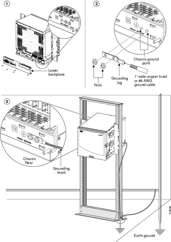 Stop. You have completed grounding the chassis. |
Locating and Grounding the Cisco ONS 15454 ETSI Chassis
Before locating and grounding the Cisco ONS 15454 ETSI chassis, you must complete the prerequisites mentioned in the Prerequisites section. To locate the ground point and attach a ground cable to the Cisco ONS 15454 ETSI chassis:
Warning |
This equipment must be grounded. Never defeat the ground conductor or operate the equipment in the absence of a suitably installed ground conductor. Contact the appropriate electrical inspection authority or an electrician if you are uncertain that suitable grounding is available. Statement 1024 |
SUMMARY STEPS
- Verify that the office ground cable is connected to the top of the bay and the office ground, according to local site practice.
- Insert the stripped end of the grounding wire into the open end of the grounding lug.
- Use the crimping tool to secure the grounding wire in two different places in the grounding lug.
- Locate the grounding receptacle on the side panel of the chassis. (See diagram 1 in the figure below.)
- Place the grounding lug against the grounding receptacle on the side panel of the chassis. (See diagram 2 in the figure below.)
- Insert one of the screws through the locking washer and through the hole in the grounding lug. Insert the screw into the threaded holes on the right side of the shelf. Ensure that the grounding lug does not interfere with other system hardware or rack equipment.
- Repeat Step 6 with the second screw.
- Prepare the other end of the grounding wire and connect it to an appropriate grounding point in your site to ensure adequate earth ground for the chassis. (See diagram 3 in the figure below.)
DETAILED STEPS
| Step 1 |
Verify that the office ground cable is connected to the top of the bay and the office ground, according to local site practice. |
| Step 2 |
Insert the stripped end of the grounding wire into the open end of the grounding lug. |
| Step 3 |
Use the crimping tool to secure the grounding wire in two different places in the grounding lug. |
| Step 4 |
Locate the grounding receptacle on the side panel of the chassis. (See diagram 1 in the figure below.) |
| Step 5 |
Place the grounding lug against the grounding receptacle on the side panel of the chassis. (See diagram 2 in the figure below.) |
| Step 6 |
Insert one of the screws through the locking washer and through the hole in the grounding lug. Insert the screw into the threaded holes on the right side of the shelf. Ensure that the grounding lug does not interfere with other system hardware or rack equipment. |
| Step 7 |
Repeat Step 6 with the second screw. |
| Step 8 |
Prepare the other end of the grounding wire and connect it to an appropriate grounding point in your site to ensure adequate earth ground for the chassis. (See diagram 3 in the figure below.) 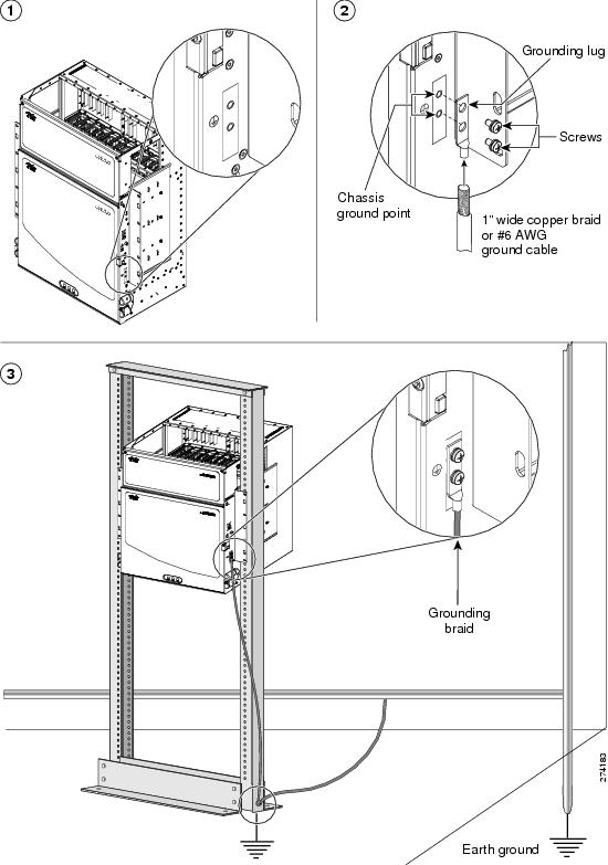 Stop. You have completed grounding the chassis. |
Locating and Grounding the Cisco ONS 15310-MA ANSI and ONS 15310-MA ETSI Chassis
Before locating and grounding the Cisco ONS 15310-MA ANSI and the ONS 15310-MA ETSI chassis, you must complete the prerequisites mentioned in the Prerequisites section. To locate the ground point and attach a ground cable to the Cisco ONS15310-MA ANSI and ONS 15310-MA ETSI chassis:
SUMMARY STEPS
- Verify that the office ground cable is connected to the top of the rack according to local site practice. (See Figure 1 and Figure 1.)
- Remove any paint and other non-conductive coatings from the surfaces between the chassis ground and the rack frame ground posts. Clean the mating surfaces and apply an appropriate antioxidant compound to the bare conductors.
- Locate the ground connection points, which are located on the left, right, and bottom of the ONS 15310-MA chassis. (See diagram 1 in the figure below.)
- Using a wire stripper, strip 0.875 inches (2.22 cm) from the end of the ground cable. Crimp the two-hole lug to the ground cable.
- Line up the holes on the lug with the holes on the ground connection point. Use two 10-32 screws to attach the lug to the ground connection point. (See diagram 2 in the figure below.)
- Attach the other end of the chassis ground cable to the rack. (See diagram 3 in the figure below.)
DETAILED STEPS
| Step 1 |
Verify that the office ground cable is connected to the top of the rack according to local site practice. (See Figure 1 and Figure 1.)
|
||||
| Step 2 |
Remove any paint and other non-conductive coatings from the surfaces between the chassis ground and the rack frame ground posts. Clean the mating surfaces and apply an appropriate antioxidant compound to the bare conductors.
|
||||
| Step 3 |
Locate the ground connection points, which are located on the left, right, and bottom of the ONS 15310-MA chassis. (See diagram 1 in the figure below.) |
||||
| Step 4 |
Using a wire stripper, strip 0.875 inches (2.22 cm) from the end of the ground cable. Crimp the two-hole lug to the ground cable. |
||||
| Step 5 |
Line up the holes on the lug with the holes on the ground connection point. Use two 10-32 screws to attach the lug to the ground connection point. (See diagram 2 in the figure below.) |
||||
| Step 6 |
Attach the other end of the chassis ground cable to the rack. (See diagram 3 in the figure below.) 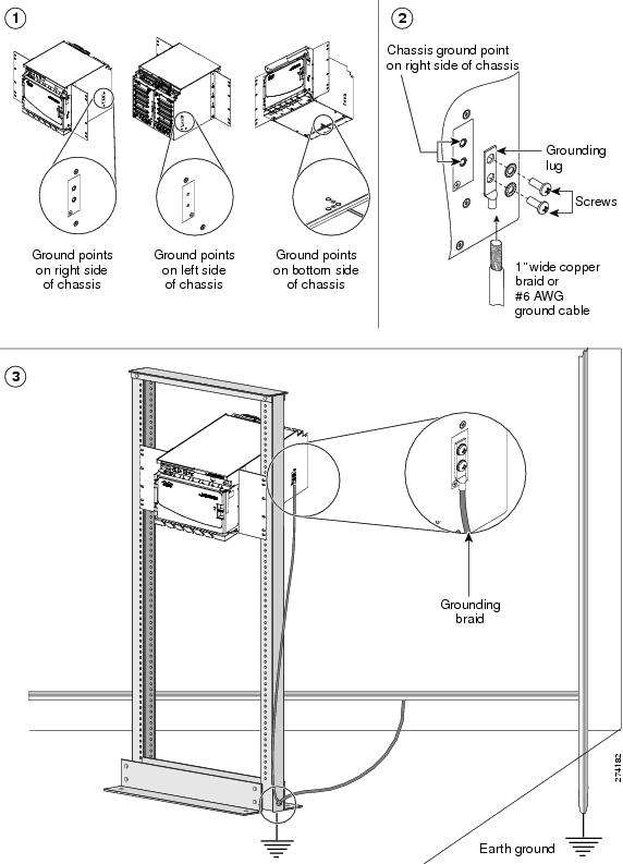 Stop. You have completed grounding the chassis. |
Locating and Grounding the Cisco ONS 15310-CL ANSI Chassis
Before locating and grounding the Cisco ONS 15310-CL ANSI chassis, you must complete the prerequisites mentioned in the Prerequisites section. To locate the ground points and attach a ground cable to the Cisco ONS 15310-CL ANSI chassis:
SUMMARY STEPS
- Verify that the office ground cable is connected to the top of the rack according to local site practice. (See Figure 1 and Figure 1.)
- Remove any paint and other non-conductive coatings from the surfaces between the shelf ground and the rack frame ground posts. Clean the mating surfaces and apply an appropriate antioxidant compound to the bare conductors.
- Using the 10-32 screws that came with the ship kit, attach one end of the chassis ground cable to the ground connection point located on the center of the rear panel as you face the chassis. Using a wire stripper, strip 0.875 inches (2.22 cm) from the end of the ground cable.
- Crimp the two-hole lug to the ground cable.
- Line up the holes on the lug with the holes on the ground connection point, located at the center of the rear panel as you face the chassis. Use two 10-32 screws to attach the lug to the ground connection point. (See diagrams 1 and 2 in the figure, below.)
- Attach the other end of the chassis ground cable to the rack. (See diagram 3 in the figure, below.)
DETAILED STEPS
| Step 1 |
Verify that the office ground cable is connected to the top of the rack according to local site practice. (See Figure 1 and Figure 1.) |
||||
| Step 2 |
Remove any paint and other non-conductive coatings from the surfaces between the shelf ground and the rack frame ground posts. Clean the mating surfaces and apply an appropriate antioxidant compound to the bare conductors.
|
||||
| Step 3 |
Using the 10-32 screws that came with the ship kit, attach one end of the chassis ground cable to the ground connection point located on the center of the rear panel as you face the chassis. Using a wire stripper, strip 0.875 inches (2.22 cm) from the end of the ground cable. |
||||
| Step 4 |
Crimp the two-hole lug to the ground cable. |
||||
| Step 5 |
Line up the holes on the lug with the holes on the ground connection point, located at the center of the rear panel as you face the chassis. Use two 10-32 screws to attach the lug to the ground connection point. (See diagrams 1 and 2 in the figure, below.) |
||||
| Step 6 |
Attach the other end of the chassis ground cable to the rack. (See diagram 3 in the figure, below.) 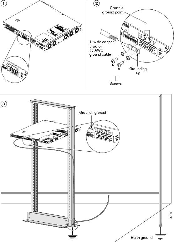 Stop. You have completed grounding the chassis. |
Locating and Grounding the Cisco ONS 15600 ANSI and ONS 15600 ETSI Bay Assembly
Before locating and grounding the Cisco ONS 15600 ANSI and Cisco ONS 15600 ETSI chassis bay assembly, you must complete the prerequisites mentioned in the Prerequisites section. To locate the ground point and attach a ground cable to the office ground from the Cisco ONS 15600 ANSI and the Cisco ONS 15600 ETSI chassis bay assembly:
Note |
The Cisco ONS 15600 ANSI and ONS 15600 ETSI chassis ground points are already connected to the grounding points on the bay assembly. |
Warning |
Never defeat the ground conductor or operate the equipment in the absence of a suitably installed ground conductor. Contact the appropriate electrical inspection authority or an electrician if you are uncertain that suitable grounding is available. Statement 213 |
Note |
Remove any paint from the two-hole lug position on the bay front ground holes and apply the antioxidant compound to this position. |
SUMMARY STEPS
- Locate the ground access points on the bay assembly of the chassis. (See diagram 1 in the figure, below.)
- Connect the office ground cable to the bay front two-hole lug position. (See diagram 2 in th figure, below.)
DETAILED STEPS
| Step 1 |
Locate the ground access points on the bay assembly of the chassis. (See diagram 1 in the figure, below.) |
| Step 2 |
Connect the office ground cable to the bay front two-hole lug position. (See diagram 2 in th figure, below.) 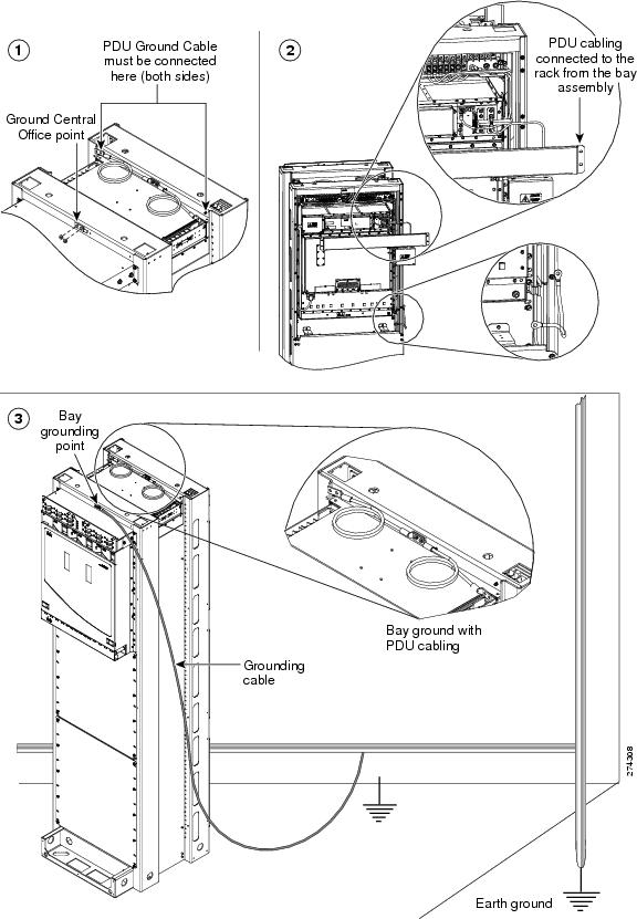 Stop. You have completed grounding the bay assembly. |
Installing the Line Cards
This section describes how to properly install the line cards. The following topics are included in this section:
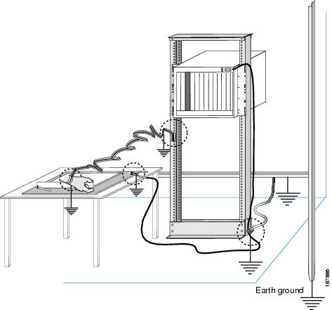
Preparing the Work Surface for Installing Line Cards
This section illustrates how you and the work surface that you are placing the line card on must be properly grounded. As shown in the figure below, ensure that you follow these steps:
- Ground yourself by wearing an ESD wrist band that is connected to the earth ground.
- Ground the table to the earth ground.
- Ground the chassis to the earth ground.
- Ground the rack to the earth ground.
Transporting Line Cards
This section illustrates how the line card must be kept in a sealed antistatic bag while being transported.
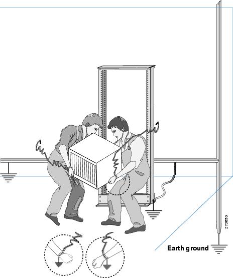
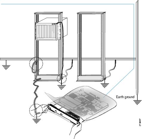
Handling Line Cards
This section illustrates how you must be properly grounded before removing the line card from the antistatic bag. It also illustrates how you must handle the line card by the front panel and the metal carrier only.
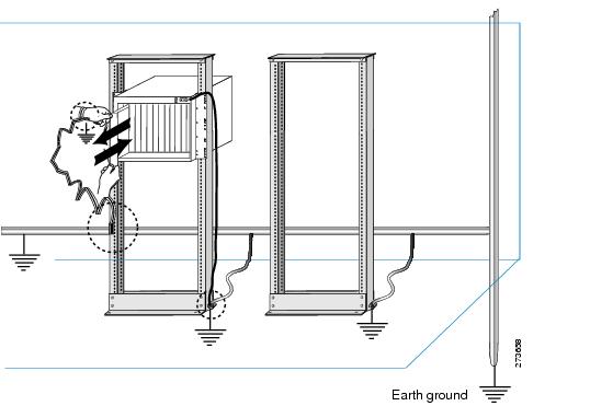
Removing and Installing Line Cards
This section illustrates the precautions to be taken while removing and installing the line cards.
Any Internet Protocol (IP) addresses used in this document are not intended to be actual addresses. Any examples, command display output, and figures included in the document are shown for illustrative purposes only. Any use of actual IP addresses in illustrative content is unintentional and coincidental.
© 2015 Cisco Systems, Inc. All rights reserved.
 Feedback