Unpacking and Installing the Cisco ONS 15454 Four-Shelf and Zero-Shelf Bay Assembly (15454-4SA-1BNC-FL, 15454-0SA-FL)
Available Languages
Table Of Contents
Unpacking and Installing the Cisco ONS 15454
Four-Shelf and Zero-Shelf Bay AssemblyCisco ONS 15454 Four-Shelf and Zero-Shelf Bay Assembly Overview
Cut and Drill Removable Floor Tile
Install the ONS 15454 Four-Shelf or Zero-Shelf Bay Assembly
Replace Side A or Side B of the FAP
Central Office Ground to Bay Wire Ground
15454 Bay Extender Kit (2.38-inch)
Obtaining Documentation and Submitting a Service Request
Unpacking and Installing the Cisco ONS 15454
Four-Shelf and Zero-Shelf Bay Assembly
Cisco ONS 15454 Four-Shelf and Zero-Shelf Bay Assembly Overview
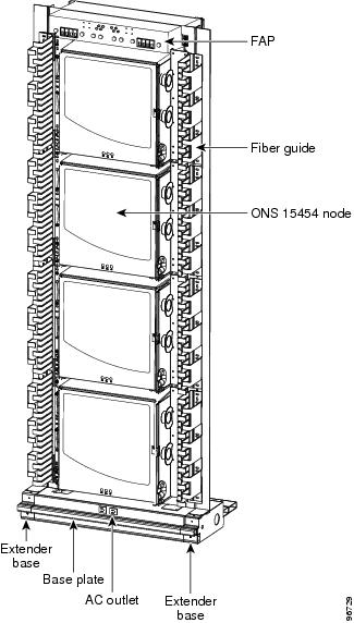
The Cisco ONS 15454 four-shelf and zero-shelf bay assemblies provide a dual-feed, pre-wired TPA-type fuse and alarm panel, two vertical fiber ducts, and two 2.38-inch vertical extenders and extender bases. The four-shelf bay assembly also provides a pre-installed, four-shelf configuration that includes four ONS 15454 shelf assemblies with electrical interface assembly (EIA) panels or EIA blank cover panels.
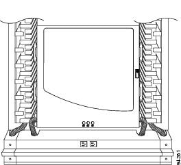
This guide describes how to unpack and install the Cisco ONS 15454 four-shelf and zero-shelf bay assembly. Because it is a complete system, installation simply requires you to remove the unit from the shipping pallet, move the unit into place, secure it, and supply power and ground attachment. Refer to the Cisco ONS 15454 user documentation for component-specific installation and replacement procedures. Figure 1 shows a four-shelf bay assembly.
This guide includes the following sections:
–
Install the ONS 15454 Four-Shelf or Zero-Shelf Bay Assembly
–
Figure 1 Four-Shelf Bay Assembly

Caution

Note
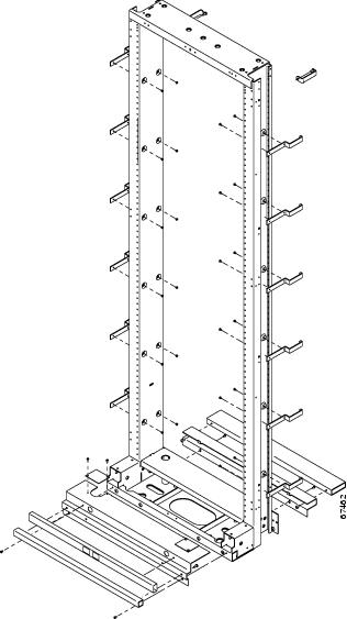
Figure 2 shows how the rack is assembled.
Figure 2 Rack assembly
Safety Recommendations
The following guidelines will help to ensure your safety and protect the equipment. This list does not include every potentially hazardous situation.
•
•
•
•
•
•
Included Material
The zero-shelf and four-shelf bay assemblies ship with the following materials:
•
•
•
•
•
•
•
•
•
•
•
In addition to the list above the four-shelf bay assembly also ships with the following materials:
•
•
•
•
•
•
•
•
Recommended Material
Because most of the installation is complete when you receive the system, the bay assembly requires little installation material. The most significant tasks are removing the packaging from the bay assembly and removing the bay assembly from the shipping pallet. Because the actual installation of the bay assembly in each facility is done according to local site practice, your material needs may vary.
Cisco recommends that you have the following items on hand for installation:
•
•
•
•
•
•
•
Cisco ONS 15454-FAP-LVD Operations Guide.Unpacking Instructions
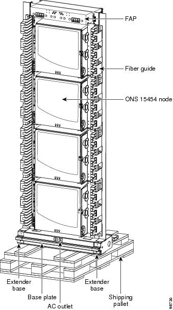
The ONS 15454 four-shelf and zero-self bay assembly ships in a corrugated container that covers the rack on its shipping pallet. After removing the corrugated container, you must remove the bolts that hold the rack to the pallet before moving the unit to the desired location. Figure 3 shows the four-shelf bay assembly on a shipping pallet.
Caution
Step 1
Step 2
Step 3
Step 4
Step 5
a.
b.
Step 6
Step 7
Figure 3 Four-Shelf Bay Assembly on a Shipping Pallet

Warning
Installation Instructions
Prior to installing the bay assembly, you should prepare your slab or raised floor plan.
Slab Floor Plan
Level Equipment
Temporarily position and level using metal shims and the equipment frame.
Drill Slab Floor
Step 1
Step 2
Step 3
Step 4
Step 5
Figure 4 Cross Section of Rack Showing Cabling Routes (Slab for Local)
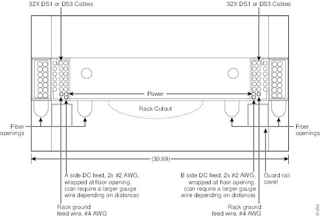
Figure 5 Slab Base Fiber Routing
Raised Floor Plan
Level Equipment
The raised floor is laser-leveled at the time of the floor installation, so no leveling blocks or shims should be necessary to level the frames. This is especially important in seismic zones 2B and higher, because leveling blocks will cause a rocking motion of the frames during an earthquake.
Cut and Drill Removable Floor Tile
Step 1
Step 2
Step 3
Step 4
Step 5
Note
Note
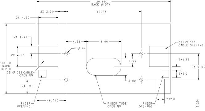
Figure 6 Raised Floor Cutout for CORE and Local
Framework Anchoring
To anchor framework to a raised floor, you must know in what earthquake zone the equipment is being installed. Zones 0-2A have the frames bolted to the raised floor through a u-channel across the bottom of the floor tile and stringers. Zones 2B-4 have 1/2-inch threaded rods extending through the raised floor and connected to seismic anchors with coupling nuts. In all zones, standard hold-down parts are used on top of the floor with threaded rods of varying lengths. Anchors and hold-down material must be engineered for proper seismic zone.
Seismic Zones 0-2A
To fasten network and unequal flange duct framework to a raised floor:
Step 1
In the base of the frame, use the hold-down plate engineered for that frame, threaded rod, nut, washer, insulating bushing, and hold-down washer.
On the bottom of the u-channel, use the clip, washer, lockwasher, and nut.
Note
Warning
Step 2
Note
Seismic Zones 2B-4
In seismic zones 2B and higher, threaded rods are run down to seismic anchors with coupling nuts from the concrete floor. U-channels are not used in higher earthquake zones. Anchor the rack at all four corners in higher earthquake zones.
Note
Install the ONS 15454 Four-Shelf or Zero-Shelf Bay Assembly
The emphasis in the following installation instructions is to position the bay assembly in your facility after it has been removed from its shipping pallet. Perform actual installation and individual node provisioning according to local site practice.
Step 1
Step 2
Step 3
Step 4
Step 5
Step 6
Step 7
Route Fiber Through the Base
Step 1
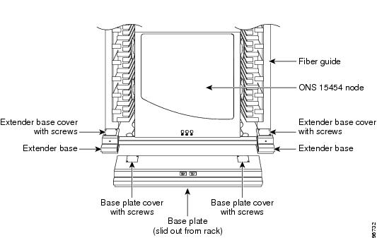
Figure 7 Sliding the Base Plate Out From the Rack
Step 2
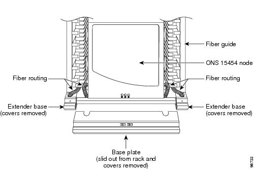
Figure 8 Base Plate and Extender Bases with Covers Removed
When the covers have been removed, you have access to the base of the rack and any holes previously cut into the raised floor tile, as shown in Figure 9.
Figure 9 Raised Floor Base Fiber Routing Close-up

You can use the base plate or extender base holes to route the fibers. Cisco recommends using the base plate holes for the bottom node and the extender base holes for the other three nodes on the four-node rack. All electrical cables will be routed in the back of the rack in the extender bases. Holes should already be cut out in the raised floor tile to compensate for any DS1, DS3, ground and power cables.
Step 3
Figure 10 Raised Floor Base Fiber Routing
Cabling Illustrations
Figure 11 through Figure 19 illustrate cabling schemes for a bay assembly.
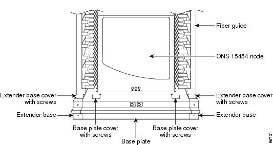
Figure 11 A Fiber Guide on a Four-Node Rack
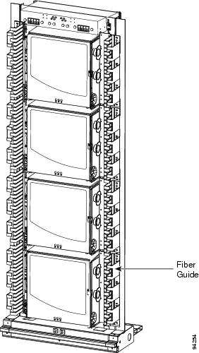
Figure 12 Rear View of a Four-Node Rack
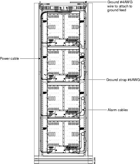
Figure 13 Side View of DS1 and Power Cables
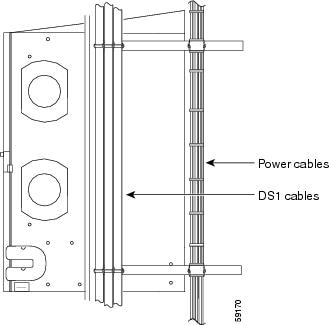
Figure 14 Close-Up of Power Cable Lacing
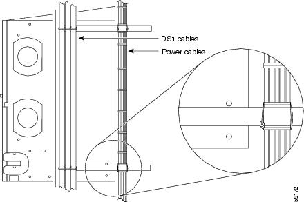
Figure 15 Side Rack View of DS1 and Power Cables
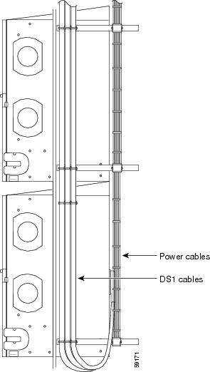
Figure 16 Cabling on One Node

Figure 17 Standoff with Wiring
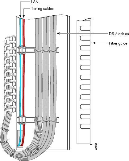
Figure 18 Standoff at Bottom of Rack
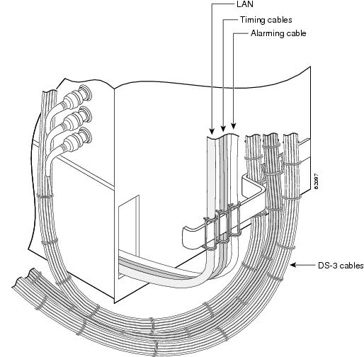
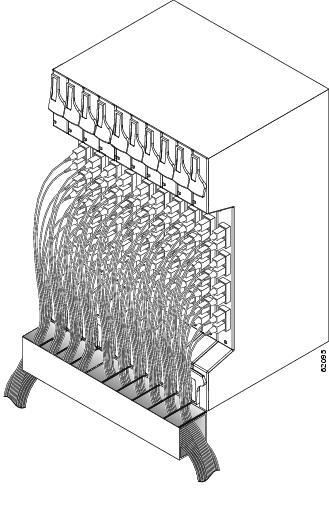
Figure 19 48 Fibers from One Node
Fuse and Alarm Panel Wiring
The FAP included in the four-shelf and zero-shelf bay assemblies provides four sets of two 30A fused drops, for powering the redundant A and B inputs of four ONS 15454 nodes. The FAP has integrated low voltage disconnect (LVD) circuitry to provide a shutdown of the output power due to a drop in input voltage from the network power source.
Necessary overload protection is provided with eight user pluggable TPA fuses, separated into two sets of four fuses, to allow for diverse routing of two power sources to each shelf assembly. Also provided is an LED alarm display for visual fault identification, with the capability for external alarm closures for remote fault signaling.
The FAP has the capability to report six alarms to a network operations center (NOC). Equipped with an alarm interface card, the ONS 15454 has the capability to report up to 32 environmental alarms, depending on which alarm interface card is installed. Only one shelf (with an AIC/AIC-I card) is needed to monitor alarming for a loss of power and a blown fuse condition. The alarms are reported to the NOC through the connected LAN wire also tied to the same shelf. Figure 20 through Figure 23 show different views of the FAP including front, rear, Side A, Side B and alarming. Refer to the latest release of the Cisco ONS 15454-FAP-LVD Operations Guide for more information on the fuse and alarm panel.
Figure 20 FAP (Front View)
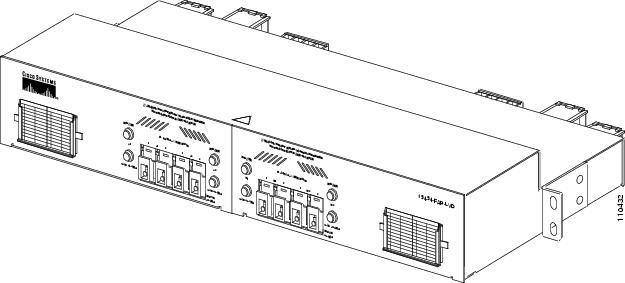
Figure 21 FAP Side A
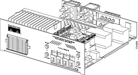
Figure 22 FAP Side B
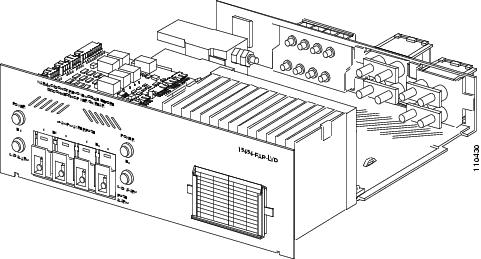
Figure 23 FAP (Rear View)

FAP Alarming
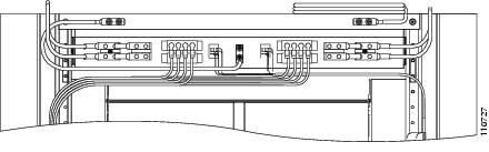
The Cisco ONS 15454 bay assemblies use 6-pair, CAT 3-rated, twisted pair wire for FAP wiring. To achieve all of the alarming capabilities of the FAP the wiring is doubled on the pins of the alarm cards. Figure 24 shows a close-up of the alarm pins and wiring. Table 1 lists the FAP wiring for each wire pair and Figure 25 shows the wire-wrap pin layout.
For assistance contact the Cisco Technical Assistance Center (TAC) at www.cisco.com or call
(800) 553-2447 for unresolved problems.Figure 24 Close-Up of FAP Alarm Pins, Alarm Wiring, and Ground

Table 1 FAP Power Alarm Wiring
Note
Perform wire-wrapping according to the T (Tip) and R (Ring) diagram in Figure 25.
Figure 25 Wire-Wrap Pin Layout in a Release 3.4 and Later ANSI Shelf Assembly

FAP Output and Input Power
Route output and input power according to local site practice. Refer to the latest release of the
Cisco ONS 15454-FAP-LVD Operations Guide for more information. Figure 26 through Figure 30 show output and input lugs and wiring and Table 2 lists lug wiring positions.Figure 26 Connecting Output Power Using Ring-Type Compression Lugs
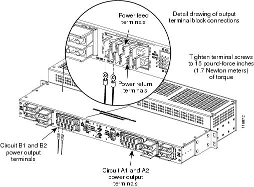
Figure 27 Close-Up of Lugs on Rear of FAP
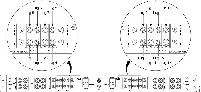
Table 2 Lug Wiring Positions
Figure 28 Lug Wiring from Rear of FAP to Shelf Lugs
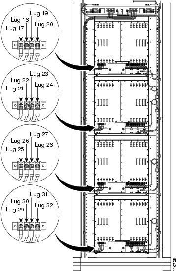
Figure 29 Connecting Input Power
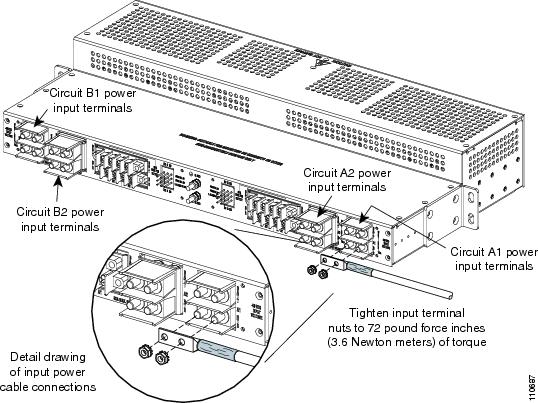
Figure 30 Wiring from Rear of FAP
Replace Side A or Side B of the FAP
Note
Step 1
Warning
Step 2
Step 3
Step 4
Step 5
Figure 31 Removing or Replacing FAP Side B

Step 6
Step 7
Step 8
Step 9
Ground and Power
The ground studs and power input and output terminals are mounted on the rear side of the FAP. The plastic protective covers install over the input and output power terminals to prevent accidental contact with the terminals when power is present in the panel.
Warning
Warning
Warning
Warning
Warning
Warning
Warning
Caution
Central Office Ground to Bay Wire Ground
Connect the CO ground to the bay wire ground according to local site practice.
Note
Central Office Power to FAP
Connect the CO power to the FAP according to local site practice.
Note
Optional Kits
There are four optional kits that can be ordered separately as needed for cable protection, aisle guards, and supplementary installation components. This section lists the kits by product name, title, and part number and provides descriptions for each kit.
Table 3 Optional Kits
15454-BAY-EXT=
74-2794-01
15454-BAY-COVER=
74-2795-01
15454-BAY-GUARD=
74-2796-01
15454-BAY-ACC1=
53-2073-01
15454 Bay Extender Kit (2.38-inch)
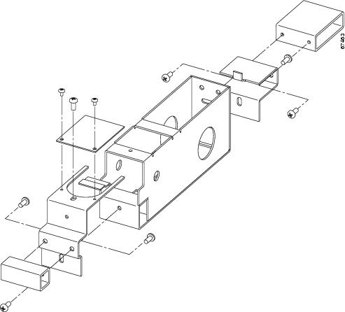
The 15454 Bay Extender Kit provides rear cable protection, additional cable management space and includes a 2.38-inch vertical extender (Figure 32) and extender base (Figure 33 and Figure 34).
Figure 32 Vertical Extender
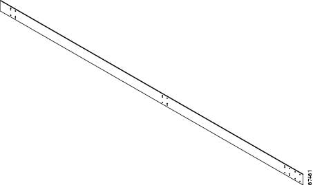
Figure 33 Extender Base
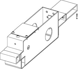
Figure 34 Extender Base Assembly
15454 Bay End Plate Cover Kit
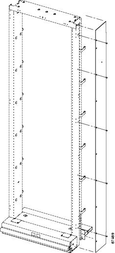
The 15454 Bay End Plate Cover Kit provides a basic end plate for temporary cable protection. It contains parts that mount flush against the rack with no major footprint change (thickness of the metal only) against the edge of the rack to protect the cables. This plate is usually used for an aisle that is not complete, or as an aisle guard for aisles. The end plate cover can be mounted with the 2.38-inch extender as shown in Figure 35 or mounted directly as shown in Figure 36.
Figure 35 End Plate Cover Assembly Mounted with 2.38-inch Extender
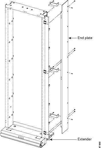
Figure 36 End Plate Cover Assembly Mounted Directly
15454 Bay End Guard Kit
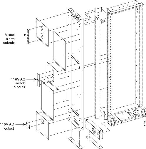
The 15454 Bay End Guard Kit provides a full aisle guard with AC on/off switch cutout. It is used to complete the end of the aisle (about 2.50-inch wide or thick). The end guard may or may not have power (110VAC), 110VAC outlets, and a visual light for alarms. See Figure 37 for end guard assembly.
Figure 37 End Guard Assembly
15454 First Aid Kit
The 15454 First Aid Kit contains extra items such as, tape, cord, tags; and cosmetic items such as, touch-up paint to promote a quality installation.
Obtaining Documentation and Submitting a Service Request
For information on obtaining documentation, submitting a service request, and gathering additional information, see the monthly What's New in Cisco Product Documentation, which also lists all new and revised Cisco technical documentation, at:
http://www.cisco.com/en/US/docs/general/whatsnew/whatsnew.html
Subscribe to the What's New in Cisco Product Documentation as a Really Simple Syndication (RSS) feed and set content to be delivered directly to your desktop using a reader application. The RSS feeds are a free service and Cisco currently supports RSS Version 2.0.
This document is to be used in conjunction with Cisco ONS 15454 user documentation and 15454-FAP-LVD documentation.

Copyright © 2004, Cisco Systems, Inc.
All rights reserved.
 Feedback
Contact Cisco
- Open a Support Case

- (Requires a Cisco Service Contract)