Installing the End Guard on the Cisco ONS 15454 High-Density Four-Shelf and Zero-Shelf Bay Assembly
Available Languages
Table Of Contents
Installing the End Guard on the
Cisco ONS 15454 High-Density Four-Shelf and Zero-Shelf Bay AssemblyObtaining Optical Networking Information
Where to Find Safety and Warning Information
Cisco Optical Networking Product Documentation CD-ROM
Obtaining Documentation, Obtaining Support, and Security Guidelines
Cisco ONS 15454 Bay End Guard Kit
Installing the End Guard on the
Cisco ONS 15454 High-Density Four-Shelf and Zero-Shelf Bay Assembly
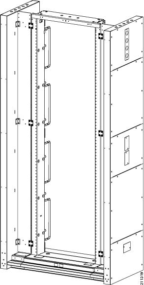
This guide describes how to unpack and install the ONS 15454 Bay End Guard Kit for the ONS 15454 four-shelf and zero-shelf bay assembly. Figure 1 shows the end guard installed on each side of a bay assembly rack.
This guide includes the following sections:
Obtaining Optical Networking Information
This section contains information that is specific to optical networking products. For information that pertains to all of Cisco, refer to the Obtaining Documentation, Obtaining Support, and Security Guidelines section.
Where to Find Safety and Warning Information
For safety and warning information, refer to the Cisco Optical Transport Products Safety and Compliance Information document that accompanied the product. This publication describes the international agency compliance and safety information for the Cisco ONS 15454 system. It also includes translations of the safety warnings that appear in the ONS 15454 system documentation.
Cisco Optical Networking Product Documentation CD-ROM
Optical networking-related documentation, including Cisco ONS 15xxx product documentation, is available in a CD-ROM package that ships with your product. The Optical Networking Product Documentation CD-ROM is updated periodically and may be more current than printed documentation.
Obtaining Documentation, Obtaining Support, and Security Guidelines
For information on obtaining documentation, obtaining support, providing documentation feedback, security guidelines, and also recommended aliases and general Cisco documents, see the monthly What's New in Cisco Product Documentation, which also lists all new and revised Cisco technical documentation, at:
http://www.cisco.com/en/US/docs/general/whatsnew/whatsnew.html
Cisco ONS 15454 Bay End Guard Kit
The ONS 15454 Bay End Guard Kit provides a full aisle guard with an AC on/off switch cutout. It is used to complete the end of the aisle (about 2.50-inches (6.35-cm) wide or thick). The end guard may or may not have power (110 VAC), 110 VAC outlets, and a visual light for alarms.

Note
Although Figure 1 shows an end guard on each side of a rack to illustrate attachments points, the normal procedure is to attach a single end guard at the end of a row of bay assembly racks.
Figure 1 Front View of Rack with End Guards Installed
Safety Recommendations
The following guidelines will help to ensure your safety and protect the equipment. This list does not include every potentially hazardous situation.
•
•
•
•
•
•
Included Material
The end guard kit ships with the following materials:
•
•
•
•
Recommended Material
Because most of the installation is complete when you receive the system, the end guard requires little installation material. The most significant tasks are removing the packaging from the end guard assembly and removing the end guard from the shipping container. Because the actual installation of the end guard in each facility is done according to local site practice, your material needs may vary.
Cisco recommends that you have the following items on hand for installation:
•
•
•
•
Unpacking Instructions
The end guard assembly ships in a crate with an integrated pallet, and is secured by eight metal clamps.
Step 1
Step 2
Step 3
Step 4
Step 5
Installation Instructions
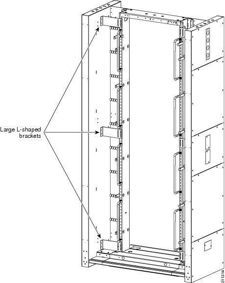
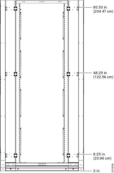
The end guard comes fully assembled, requiring only attachment to the side of the bay assembly rack. General bracket locations are shown in Figure 2 and Figure 3. Specific locations for installing the small brackets are shown in Figure 4.
Step 1
Step 2
Step 3
Step 4
Step 5
Step 6
Step 7
Step 8
Figure 2 End Guard Installation (Front View of Rack)
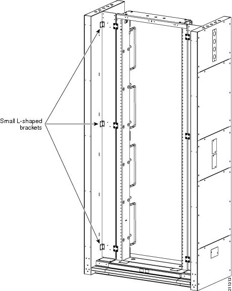
Figure 3 End Guard Installation (Rear View of Rack)
Bracket Location
Figure 4 shows the height in inches, measured from the floor, for locating the small brackets when installing the end guard.
Figure 4 End Guard Installation (Front Bracket Location)
This document is to be used in conjunction with Cisco ONS 15454 user documentation and 15454-FAP-LVD documentation.

Copyright © 2007, Cisco Systems, Inc.
All rights reserved.
 Feedback
Contact Cisco
- Open a Support Case

- (Requires a Cisco Service Contract)