- About this Guide
- Chapter 1, Cisco ONS 15454 (ANSI and ETSI), ONS 15454 M2, and ONS 15454 M6 Shelf Assembly
- Chapter 2, Common Control Cards
- Chapter 3, Optical Service Channel Cards
- Chapter 4, Optical Amplifier Cards
- Chapter 5, Multiplexer and Demultiplexer cards
- Chapter 6, Tunable Dispersion Compensating Units
- Chapter 7, Protection Switching Module
- Chapter 8, Optical Add/Drop Cards
- Chapter 9, Reconfigurable Optical Add/Drop Cards
- Chapter 10, Transponder and Muxponder Cards
- Chapter 11, Node Reference
- Chapter 12, Network Reference
- Chapter 13, Optical Circuit Reference
- Chapter 14, Cisco Transport Controller Operation
- Chapter 15, Security Reference
- Chapter 16, Timing Reference
- Chapter 17, Manage Network Connectivity
- Chapter 18, Alarm Management
- Chapter 19, Performance Monitoring
- Chapter 20, SNMP
- Appendix A, Hardware Specifications
- Appendix B, Administrative and Service States
- Appendix C, Pseudo Command Line Interface Reference
- Appendix D, Fiber and Connector Losses in Raman Link Configuration
- Appendix E, Network Element Defaults
Cisco ONS 15454 DWDM Reference Manual, Release 9.2
Bias-Free Language
The documentation set for this product strives to use bias-free language. For the purposes of this documentation set, bias-free is defined as language that does not imply discrimination based on age, disability, gender, racial identity, ethnic identity, sexual orientation, socioeconomic status, and intersectionality. Exceptions may be present in the documentation due to language that is hardcoded in the user interfaces of the product software, language used based on RFP documentation, or language that is used by a referenced third-party product. Learn more about how Cisco is using Inclusive Language.
- Updated:
- August 26, 2012
Chapter: Chapter 11, Node Reference
- 11.1 DWDM Node Configurations
- 11.2 Supported Node Configurations for OPT-RAMP-C and OPT-RAMP-CE Cards
- 11.3 Supported Node Configurations for PSM Card
- 11.4 Multishelf Node
- 11.5 Optical Sides
- 11.6 Configuring Mesh DWDM Networks
- 11.6.1 Line Termination Mesh Node Using 40-WXC-C Cards
- 11.6.1.1 40-Channel Omni-directional n-degree ROADM Node
- 11.6.1.2 40-Channel Colorless n-Degree ROADM Node
- 11.6.1.3 40-Channel Colorless and Omni-directional n-Degree ROADM Node
- 11.6.2 Line Termination Mesh Node Using 80-WXC-C Cards
- 11.6.2.1 80-Channel Omni-directional n-degree ROADM Node
- 11.6.2.2 80-Channel Colorless n-degree ROADM Node
- 11.6.2.3 80-Channel Colorless and Omni-directional n-Degree ROADM Node
- 11.6.3 Line Termination Mesh Node Using 40-SMR2-C Cards
- 11.6.4 XC Terminatio n Mesh Node
- 11.6.5 Mesh Patch Panels and Shelf Layouts
- 11.6.6 Using a Mesh Node With Omni-Directional Add/Drop Section
- 11.7 DWDM Node Cabling
- 11.7.1 OSC Link Termination Fiber-Optic Cabling
- 11.7.2 Hub Node Fiber-Optic Cabling
- 11.7.3 Terminal Node Fiber-Optic Cabling
- 11.7.4 Line Amplifier Node Fiber-Optic Cabling
- 11.7.5 OSC Regeneration Node Fiber-Optic Cabling
- 11.7.6 Amplified or Passive OADM Node Fiber-Optic Cabling
- 11.7.7 ROADM Node Fiber-Optic Cabling
- 11.8 Automatic Node Setup
- 11.9 DWDM Functional View
- 11.9.1 Navigating Functional View
- 11.9.2 Using the Graphical Display
- 11.9.2.1 Displaying a Side
- 11.9.2.2 Displaying Card Information
- 11.9.2.3 Displaying Port Information
- 11.9.2.4 Displaying Patchcord Information
- 11.9.2.5 Displaying MPO Information
- 11.9.2.6 Alarm Box Information
- 11.9.2.7 Transponder and Muxponder Information
- 11.9.2.8 Changing the Views
- 11.9.2.9 Selecting Circuits
- 11.9.2.10 Displaying Optical Path Power
- 11.10 DWDM Network Functional View
- 11.11 Non-DWDM (TDM) Networks
Node Reference
This chapter explains the ONS 15454 dense wavelength division multiplexing (DWDM) node types that are available for the ONS 15454. The DWDM node type is determined by the type of amplifier and filter cards that are installed in an ONS 15454. The chapter also explains the DWDM automatic power control (APC), reconfigurable optical add/drop multiplexing (ROADM) power equalization, span loss verification, and automatic node setup (ANS) functions.

Note![]() Unless otherwise specified, “ONS 15454” refers to both ANSI and ETSI shelf assemblies.
Unless otherwise specified, “ONS 15454” refers to both ANSI and ETSI shelf assemblies.
Note![]() In this chapter, “OPT-BST” refers to the OPT-BST, OPT-BST-E, OPT-BST-L cards, and to the OPT-AMP-L and OPT-AMP-17-C cards when they are provisioned in OPT-LINE (optical booster) mode. “OPT-PRE” refers to the OPT-PRE card and to the OPT-AMP-L and OPT-AMP-17-C cards provisioned in OPT-PRE (preamplifier) mode.
In this chapter, “OPT-BST” refers to the OPT-BST, OPT-BST-E, OPT-BST-L cards, and to the OPT-AMP-L and OPT-AMP-17-C cards when they are provisioned in OPT-LINE (optical booster) mode. “OPT-PRE” refers to the OPT-PRE card and to the OPT-AMP-L and OPT-AMP-17-C cards provisioned in OPT-PRE (preamplifier) mode.
11.1 DWDM Node Configurations
The ONS 15454 supports the following DWDM node configurations: hub, terminal, optical add/drop multiplexing (OADM), reconfigurable OADM (ROADM), anti-amplified spontaneous emission (anti-ASE), line amplifier, optical service channel (OSC) regeneration line, multishelf nodes, and node configurations for mesh networks. All node configurations can be provisioned with C-band or L-band cards except the OADM and anti-ASE nodes. These nodes require AD-xB-xx.x or AD-xC-xx.x cards, which are C-band only. All node configurations can be single-shelf or multishelf.
Note![]() The Cisco TransportPlanner tool creates a plan for amplifier placement and proper node equipment.
The Cisco TransportPlanner tool creates a plan for amplifier placement and proper node equipment.
Note![]() To support multiple optical sides in mesh DWDM networks, east and west are no longer used to reference the left and right sides of the ONS 15454 shelf. If a network running a previous software release is upgraded to this release, west will be mapped to A and east to B. In two-sided nodes, such as a hub or ROADM node, Side A refers to Slots 1 through 6 and Side B refers to Slots 12 through 17. Terminal nodes have one side labeled “A,” regardless of which slots have cards installed. For more information about configuring the ONS 15454 in mesh DWDM networks, see the “Configuring Mesh DWDM Networks” section.
To support multiple optical sides in mesh DWDM networks, east and west are no longer used to reference the left and right sides of the ONS 15454 shelf. If a network running a previous software release is upgraded to this release, west will be mapped to A and east to B. In two-sided nodes, such as a hub or ROADM node, Side A refers to Slots 1 through 6 and Side B refers to Slots 12 through 17. Terminal nodes have one side labeled “A,” regardless of which slots have cards installed. For more information about configuring the ONS 15454 in mesh DWDM networks, see the “Configuring Mesh DWDM Networks” section.
11.1.1 Terminal Node
A terminal node is a single ONS 15454 node equipped with two TCC2/TCC2P/TCC3/TNC/TSC cards and one of the following combinations:
- One 32MUX-O card and one 32DMX-O card
- One 32WSS card and either a 32DMX or a 32DMX-O card
- One 40-WSS-C or 40-WSS-CE card and one 40-DMX-C or 40-DMX-CE card
- One 40-MUX-C and one 40-DMX-C or 40-DMX-CE card
- One 80-WXC-C card, one 15216-MD-40-ODD, 15216-EF-40-ODD, or 15216-MD-48-ODD patch panel, and one 15216-MD-40-EVEN, 15216-EF-40-EVEN, or 15216-MD-48-EVEN (ONS 15216 40 or 48-channel mux/demux patch panel), and 15216-MD-ID-50 or 15216-MD-48-CM
- One 40-SMR1-C and one 15216-MD-40-ODD, 15216-EF-40-ODD, or 15216-MD-48-ODD patch panel
- One 40-SMR2-C and one 15216-MD-40-ODD, 15216-EF-40-ODD, or 15216-MD-48-ODD patch panel
Note![]() Although it is recommended that you use the 15216-MD-40-ODD, 15216-EF-40-ODD, or 15216-MD-48-ODD patch panel along with the 40-SMR1-C and 40-SMR2-C cards, you can alternatively use the 40-MUX-C and 40-DMX-C cards instead of the 15216-EF-40-ODD, or 15216-MD-48-ODD patch panel.
Although it is recommended that you use the 15216-MD-40-ODD, 15216-EF-40-ODD, or 15216-MD-48-ODD patch panel along with the 40-SMR1-C and 40-SMR2-C cards, you can alternatively use the 40-MUX-C and 40-DMX-C cards instead of the 15216-EF-40-ODD, or 15216-MD-48-ODD patch panel.
Cards in the terminal nodes can be installed in Slots 1 through 6 or Slots 12 through 17. The side where cards are installed is always assigned as Side A.
Figure 11-1 shows an example of a terminal configuration with a 2MUX-O card installed. The channel flow for a terminal node is the same as the hub node (Figure 11-28).
Figure 11-1 Terminal Node Configuration With 32MUX-O Cards Installed
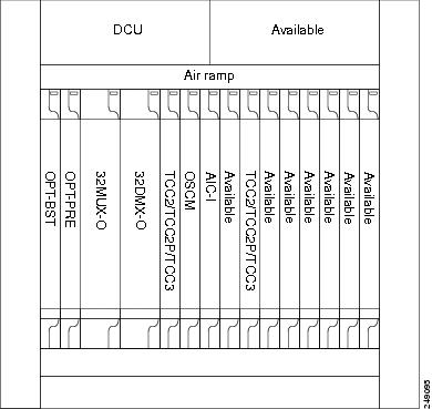
Figure 11-2 shows an example of a terminal configuration with a 40-WSS-C card installed.
Figure 11-2 Terminal Node Configuration with 40-WSS-C Cards Installed
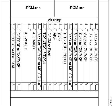
Figure 11-3 shows an example of a terminal configuration with a 40-MUX-C card installed.
Figure 11-3 Terminal Node with 40-MUX-C Cards Installed
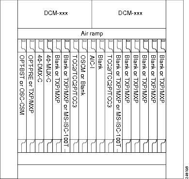
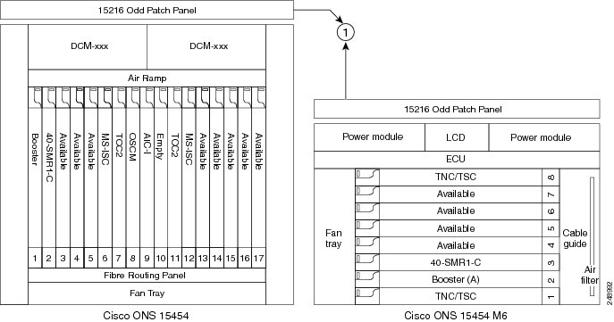
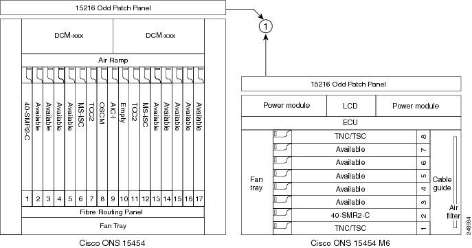
Figure 11-4 shows an example of a terminal configuration with a 40-SMR1-C card installed.
Figure 11-4 Terminal Node with 40-SMR1-C Card Installed - Cisco ONS 15454 and Cisco ONS 15454 M6

|
|
|
Figure 11-5 shows an example of a terminal configuration with 40-SMR1-C and booster amplifier cards installed.
Figure 11-5 Terminal Node with 40-SMR1-C and Booster Amplifier Cards Installed - Cisco ONS 15454 and Cisco ONS 15454 M6
|
|
|
Note![]() When you use the 40-SMR1-C card along with a booster amplifier, the OSCM card must be connected to the booster amplifier.
When you use the 40-SMR1-C card along with a booster amplifier, the OSCM card must be connected to the booster amplifier.
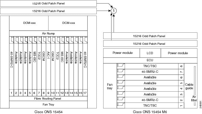
Figure 11-6 shows an example of a terminal configuration with a 40-SMR2-C card installed.
Figure 11-6 Terminal Node with 40-SMR2-C Card Installed - Cisco ONS 15454 and Cisco ONS 15454 M6
|
|
|
11.1.2 OADM Node
An OADM node is a single ONS 15454 node equipped with cards installed on both sides and at least one AD-xC-xx.x card or one AD-xB-xx.x card and two TCC2/TCC2P/TCC3/TNC/TSC cards. This configuration supports 32 channels. In an OADM node, channels can be added or dropped independently from each direction and then passed through the reflected bands of all OADMs in the DWDM node (called express path). They can also be passed through one OADM card to another OADM card without using a TDM ITU-T line card (called optical pass-through) if an external patchcord is installed.
Unlike express path, an optical pass-through channel can be converted later to an add/drop channel in an altered ring without affecting another channel. OADM amplifier placement and required card placement is determined by the Cisco TransportPlanner tool or your site plan.
OADM nodes can be amplified or passive. In amplified OADMs, booster and preamplifier cards are installed on bode sides of the node. Figure 11-7 shows an example of an amplified OADM node configuration. In addition, OADM nodes can be asymmetric. Amplifiers may be installed in one side, but not the other. Or preamplifiers may be installed in one side, and a booster in the other.
Figure 11-7 Amplified OADM Node Configuration Example
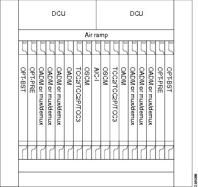
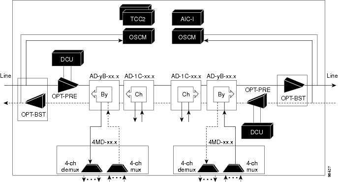
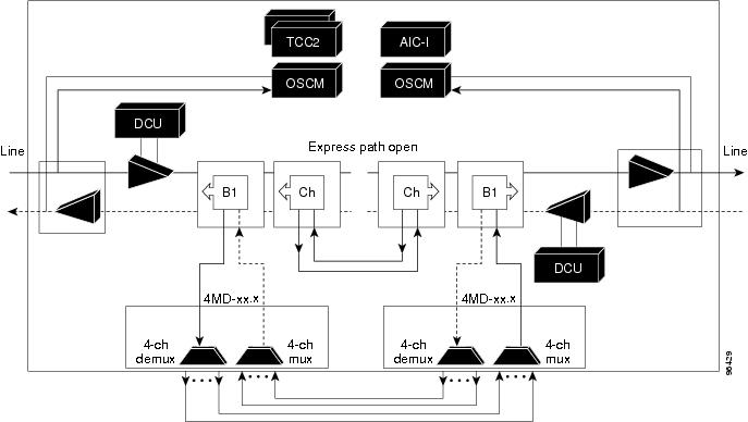
Figure 11-8 shows an example of the channel flow on the amplified OADM node. Since the 32-wavelength plan is based on eight bands (each band contains four channels), optical adding and dropping can be performed at the band level and/or at the channel level (meaning individual channels can be dropped).
Figure 11-8 Amplified OADM Node Channel Flow Example
11.1.3 ROADM Node
A ROADM node adds and drops wavelengths without changing the physical fiber connections. A ROADM node is equipped with two TCC2/TCC2P/TCC3/TNC/TSC cards and one of the following combinations:
- Two 32WSS cards and optionally, two 32DMX or 32DMX-O cards
- Two 40-WSS-C or 40-WSS-CE cards and optionally, two 40-DMX-C or 40-DMX-CE cards
- Two 40-SMR1-C cards and two 15216-MD-40-ODD, 15216-EF-40-ODD, or 15216-MD-48-ODD (ONS 15216 40 or 48-channel mux/demux) patch panels
- Two 40-SMR2-C cards and two 15216-MD-40-ODD, 15216-EF-40-ODD, or 15216-MD-48-ODD (ONS 15216 40 or 48-channel mux/demux) patch panels
- Two 80-WXC-C cards and two 15216-MD-40-ODD, 15216-EF-40-ODD, 15216-MD-48-ODD, 15216-MD-40-EVEN, 15216-EF-40-EVEN, or 15216-MD-48-EVEN patch panels
Note![]() Although it is recommended that you use the 15216-MD-40-ODD, 15216-EF-40-ODD, or 15216-MD-48-ODD patch panel along with the 40-SMR1-C and 40-SMR2-C cards, you can alternatively use the 40-MUX-C and 40-DMX-C cards instead of the 15216-MD-40-ODD, 15216-EF-40-ODD, or 15216-MD-48-ODD patch panel.
Although it is recommended that you use the 15216-MD-40-ODD, 15216-EF-40-ODD, or 15216-MD-48-ODD patch panel along with the 40-SMR1-C and 40-SMR2-C cards, you can alternatively use the 40-MUX-C and 40-DMX-C cards instead of the 15216-MD-40-ODD, 15216-EF-40-ODD, or 15216-MD-48-ODD patch panel.
Transponders (TXPs) and muxponders (MXPs) can be installed in Slots 6 and 12 and, if amplification is not used, in any open slot.
Note![]() Although not required, 32DMX-O can be used in a ROADM node. Cisco TransportPlanner automatically chooses the demultiplexer card that is best for the ROADM node based on the network requirements.
Although not required, 32DMX-O can be used in a ROADM node. Cisco TransportPlanner automatically chooses the demultiplexer card that is best for the ROADM node based on the network requirements.
Figure 11-9 shows an example of an amplified ROADM node configuration with 32DMX cards installed.
Figure 11-9 ROADM Node with 32DMX Cards Installed
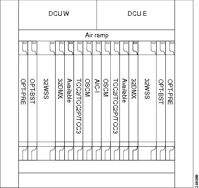
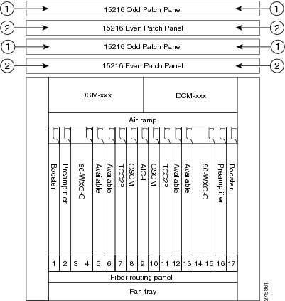
Figure 11-10 shows an example of an amplified ROADM node configuration with 40-WSS-C cards installed.
Figure 11-10 ROADM Node with 40-WSS-C Cards Installed
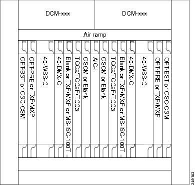
Figure 11-11 shows an example of a ROADM node with 40-SMR1-C cards installed.
Figure 11-11 ROADM Node with 40-SMR1-C Cards Installed - Cisco ONS 15454 and Cisco ONS 15454 M6

|
|
|
Figure 11-12 shows an example of a ROADM node with 40-SMR1-C and booster amplifier cards installed.
Figure 11-12 ROADM Node with 40-SMR1-C and Booster Amplifier Cards Installed - Cisco ONS 15454 and Cisco ONS 15454 M6
|
|
|
Note![]() When you use the 40-SMR1-C card along with a booster amplifier, the OSCM card must be connected to the booster amplifier.
When you use the 40-SMR1-C card along with a booster amplifier, the OSCM card must be connected to the booster amplifier.
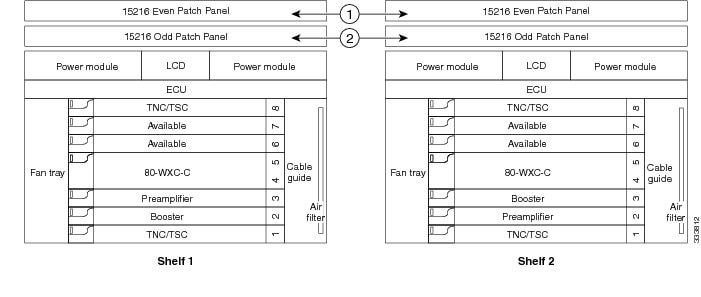
Figure 11-13 shows an example of a ROADM node with 40-SMR2-C cards installed.
Figure 11-13 ROADM Node with 40-SMR2-C Cards Installed - 15454 - Cisco ONS 15454 and Cisco ONS 15454 M6
|
|
|
Figure 11-14 shows the layout of a 80-channel colored two-degree ROADM node.
Figure 11-14 80-Channel Colored Two-Degree ROADM Node
|
|
|
|
|
|
The 80-WXC-C cards are inserted in Slots 3 and 14, and function in the bidirectional mode.
Figure 11-15 shows the layout of an ONS 15454 M6 80-channel colored two-degree ROADM node.
Figure 11-15 ONS 15454 M6 80-Channel Colored Two-degree ROADM Node
|
|
|
|
|
|
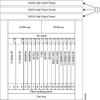
Figure 11-16 shows the layout of an 80-channel n-degree ROADM node with omni-directional side.
Figure 11-16 80-Channel n-degree ROADM node with Omni-directional Side
|
|
|
|
|
|
Figure 11-17 shows the layout of an ONS 15454 M6 80-channel n-degree ROADM node with omni-directional side.
Figure 11-17 ONS 15454 M6 80-Channel n-degree ROADM node with Omni-directional Side
|
|
|
|
|
|
Figure 11-18 shows the layout of a 40-channel n-degree ROADM node with a 40-WXC-C based colorless side.
Figure 11-18 40-Channel n-degree ROADM Node with 40-WXC-C Based Colorless Side
The 80-WXC-C cards are connected to the ADD/DROP ports of the 40-WXC-C card and function as colorless multiplexer and demultiplexer units.
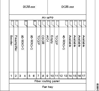
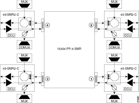
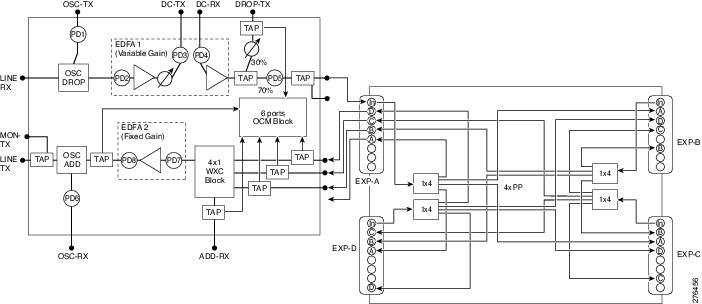
Figure 11-19 shows the layout of a 40-channel four-degree ROADM node with a 40-SMR2-C based colorless side.
Figure 11-19 40-Channel Four-degree ROADM Node with 40-SMR2-C Based Colorless Side
|
|
|
The 80WXC-C (multiplexer) card is inserted in Slot 3 and the 80-WXC-C (demultiplexer) card is inserted in Slot 5. The 80-WXC-C cards are connected to the ADD/DROP ports of the 40-SMR2-C card and function as the colorless multiplexer and demultiplexer units.
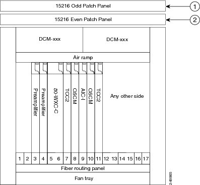
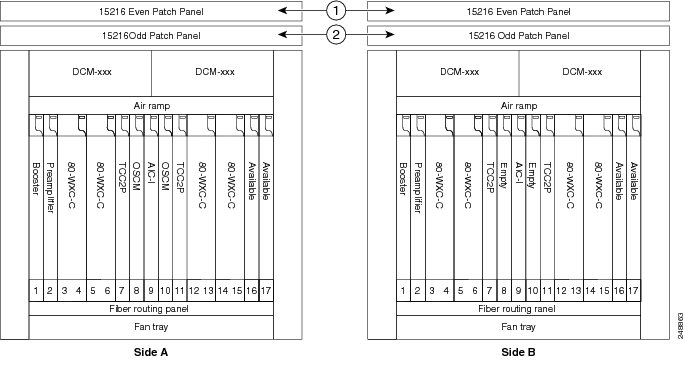
Figure 11-20 shows the layout for an 80-channel colorless ROADM node.
Figure 11-20 80-Channel Colorless ROADM Node
|
|
|
|
|
|
An 80 channel colorless two-degree ROADM node requires the following cards: 80-WXC-C, 15216-MD-40-ODD, 15216-EF-40-ODD, 15216-MD-48-ODD, 15216-MD-40-EVEN, 15216-EF-40-EVEN, 15216-MD-48-EVEN, preamplifiers, and boosters.
The 80-WXC-C cards can be used at two levels; level1 (L1) and level2 (L2).
The L1 80WXC-C (multiplexer) card is inserted in Slot 3 and the L1 80-WXC-C (demultiplexer) card is inserted in Slot 5. The L2 80WXC-C (multiplexer) card is inserted in Slot 12 and the L2 80-WXC-C (demultiplexer) card is inserted in Slot 14.
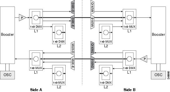
Figure 11-21 shows an example of the optical signal flow in an 80-channel colorless two-degree ROADM node from Side A to Side B using 80-WXC-C cards. The optical signal flow from Side B to Side A follows an identical path.
Figure 11-21 80-Channel Colorless Two-degree ROADM Node
|
|
The booster on Side A receives the composite optical signal. It separates the optical service channel from the optical payload and sends the payload to the preamplifier on Side A. |
|
|
The preamplifier compensates for chromatic dispersion, amplifies the optical payload and sends it to the L1 80-WXC-C card (demultiplexer). |
|
|
Up to eight colorless ports are available on the L1 80-WXC-C card if no colored wavelength is terminated. In Figure 11-21, two EAD ports are connected to 40-DMX-C or 40-DMX-CE cards, 15216-MD-40-ODD, 15216-EF-40-ODD, 15216-MD-48-ODD, 15216-MD-40-EVEN, 15216-EF-40-EVEN, or 15216-MD-48-EVEN units where the colored odd and even wavelengths are dropped. The express wavelengths are sent to the L1 80-WXC-C card (multiplexer) on Side B where the wavelengths are multiplexed with other colored or colorless wavelengths. |
|
|
The L1-80-WXC-C card on Side B sends the composite signal to the booster on Side B. |
|
|
The booster on Side B receives the composite optical signal, adds the optical service channel to the optical payload and sends it to the transmission line. |
|
|
It is possible to configure more colorless ports by cascading the 80-WXC-C cards at two levels. For example, to get 14 colorless ports connect one of the EAD ports of the L1 80-WXC-C card to another 80-WXC-C cards at level 2. There are five colorless ports on the L1 80-WXC-C card and nine colorless ports on the L2 80-WXC-C card. To achieve an 80 channel colorless configuration, connect nine L2 80-WXC-C cards to the nine EAD ports of the L1 80-WXC-C card. |
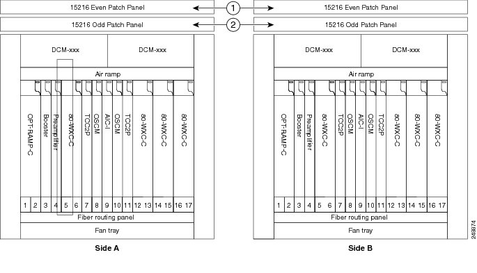
Figure 11-22 shows the layout for an 80-channel colorless ROADM node with OPT-RAMP-C cards.
Figure 11-22 80-Channel Colorless ROADM Node with OPT-RAMP-C Card
|
|
|
|
|
|
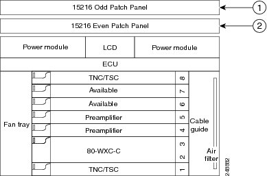
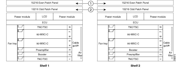
Figure 11-23 shows an example of an ONS 15454 M6 80-channel two degree colorless ROADM node.
Figure 11-23 ONS 15454 M6 80-Channel Two-degree Colorless ROADM Node
|
|
|
|
|
|
The L1 80WXC-C (multiplexer) card is inserted in Slot 4 and the L1 80-WXC-C (demultiplexer) is inserted in Slot 6. The L2 80WXC-C (multiplexer) card is inserted in Slot 2 and the L2 80-WXC-C (demultiplexer) is inserted in Slot 4.
Figure 11-24 shows an example of a ROADM optical signal flow from Side A to Side B using the 32WSS or 40-WSS-C cards. The optical signal flow from Side B to Side A follows an identical path through the Side B OSC-CSM and 32WSS or 40-WSS-C cards. In this example, OSC-CSM cards are installed, hence OPT-BSTs are not needed.
Figure 11-24 ROADM Optical Signal Flow Example Using 32WSS or 40-WSS-C Card
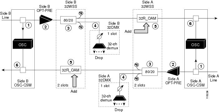
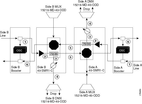
Figure 11-25 shows an example of an ROADM optical signal flow from Side A to Side B using the 40-SMR1-C card. The optical signal flow from Side B to Side A follows an identical path through the Side B booster and 40-SMR1-C card.
Figure 11-25 ROADM Optical Signal Flow Example Using 40-SMR1-C Card
11.1.4 Hub Node
A hub node is a single ONS 15454 node equipped with two TCC2/TCC2P/TCC3/TNC/TSC cards and one of the following combinations:
- Two 32MUX-O cards and two 32DMX-O or 32DMX cards
- Two 32WSS cards and two 32DMX or 32DMX-O cards
- Two 40-WSS-C or 40-WSS-CE cards and two 40-DMX-C or 40DMX-CE cards
- Two 40-SMR1-C and two 15216-MD-40-ODD, 15216-EF-40-ODD, or 15216-MD-48-ODD (ONS 15216 40 or 48-channel mux/demux patch panel)
- Two 40-SMR2-C and two 15216-MD-40-ODD, 15216-EF-40-ODD, or 15216-MD-48-ODD
Note![]() Although it is recommended that you use the 15216-MD-40-ODD, 15216-EF-40-ODD, or 15216-MD-48-ODD card along with the 40-SMR1-C and 40-SMR2-C cards, you can alternatively use the 40-MUX-C and 40-DMX-C cards instead of the 15216-MD-40-ODD, 15216-EF-40-ODD, or 15216-MD-48-ODD card.
Although it is recommended that you use the 15216-MD-40-ODD, 15216-EF-40-ODD, or 15216-MD-48-ODD card along with the 40-SMR1-C and 40-SMR2-C cards, you can alternatively use the 40-MUX-C and 40-DMX-C cards instead of the 15216-MD-40-ODD, 15216-EF-40-ODD, or 15216-MD-48-ODD card.
Note![]() The configuration for a hub node using 40-SMR1-C or 40-SMR2-C cards is identical to the ROADM node, except that there is no patchcord connecting the two 40-SMR1-C or 40-SMR2-C cards. For more details on the ROADM node configuration, see the “ROADM Node” section.
The configuration for a hub node using 40-SMR1-C or 40-SMR2-C cards is identical to the ROADM node, except that there is no patchcord connecting the two 40-SMR1-C or 40-SMR2-C cards. For more details on the ROADM node configuration, see the “ROADM Node” section.
Note![]() The 32WSS/40-WSS-C/40-WSS-CE and 32DMX/32DMX-L/40-DMX-C/ 40-DMX-CE cards are normally installed in ROADM nodes, but they can also be installed in hub and terminal nodes. If the cards are installed in a hub node, the 32WSS/32WSS-L/ 40-WSS-C/40-WSS-CE express ports (EXP RX and EXP TX) are not cabled.
The 32WSS/40-WSS-C/40-WSS-CE and 32DMX/32DMX-L/40-DMX-C/ 40-DMX-CE cards are normally installed in ROADM nodes, but they can also be installed in hub and terminal nodes. If the cards are installed in a hub node, the 32WSS/32WSS-L/ 40-WSS-C/40-WSS-CE express ports (EXP RX and EXP TX) are not cabled.
A dispersion compensation unit (DCU) can also be added, if necessary. Figure 11-26 shows a hub node configuration with 32MUX-O and 32DMX-O cards installed.
Figure 11-26 Hub Node Configuration Example with 32-Channel C-Band Cards
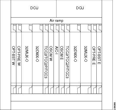
Figure 11-27 shows a 40-channel hub node configuration with 40-WSS-C cards installed.
Figure 11-27 Hub Node Configuration Example with 40-WSS-C Cards

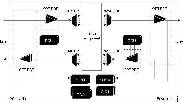
Figure 11-28 shows the channel flow for a hub node. Up to 32 channels from the client ports are multiplexed and equalized onto one fiber. Then, multiplexed channels are transmitted to the OPT-BST amplifier. The OPT-BST output is combined with an output signal from the OSCM card and transmitted to the other side.
Received signals are divided between the OSCM card and an OPT-PRE card. Dispersion compensation is applied to the signal received by the OPT-PRE amplifier, and it is then sent to the 32DMX-O card, which demultiplexes and attenuates the input signal.
Figure 11-28 Hub Node Channel Flow Example
11.1.5 Anti-ASE Node
In a mesh ring network, the ONS 15454 requires a node configuration that prevents ASE accumulation and lasing. An anti-ASE node can be created by configuring a hub node or an OADM node with some modifications. No channels can travel through the express path, but they can be demultiplexed and dropped at the channel level on one side and added and multiplexed on the other side.
The hub node is the preferred node configuration when some channels are connected in pass-through mode. For rings that require a limited number of channels, combine AD-xB-xx.x and 4MD-xx.x cards, or cascade AD-xC-xx.x cards. See Figure 11-8.
Figure 11-29 shows an anti-ASE node that uses all wavelengths in the pass-through mode. Use Cisco TransportPlanner to determine the best configuration for anti-ASE nodes.
Figure 11-29 Anti-ASE Node Channel Flow Example
11.1.6 Line Amplifier Node
A line amplifier node is a single ONS 15454 node that is used to amplify the optical signal in long spans. The line amplifier node can be equipped with one of the following sets of cards:
- Two OPT-PRE cards, two OPT-BST cards, and two OSCM cards
- Two OPT-PRE cards and two OSC-CSM cards
- Two OPT-AMP-17-C cards and two OSCM cards
- Two OPT-AMP-C cards and two OSCM cards
Attenuators might also be required between each preamplifier and OPT-BST amplifier to match the optical input power value and to maintain the amplifier gain tilt value.
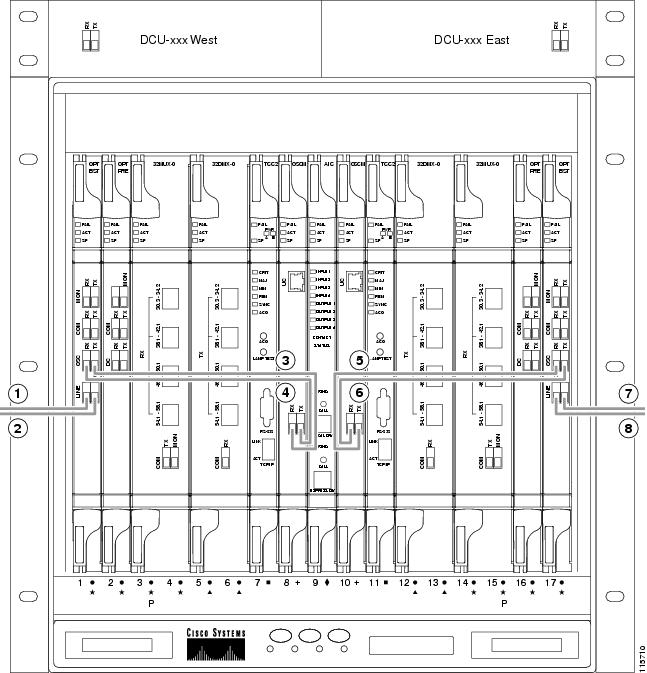
Two OSCM cards are connected to the OPT-BST cards to multiplex the OSC signal with the pass-though channels. If the node does not contain a booster card, OSC-CSM cards must be installed instead of OSCM cards. Figure 11-30 shows an example of a line amplifier node configuration using OPT-BST, OPT-PRE, and OSCM cards.
Figure 11-30 Line Amplifier Node Configuration Example - Cisco ONS 15454 M6 and Cisco ONS 15454 M2
11.1.7 OSC Regeneration Node
The OSC regeneration node is added to the DWDM networks for two purposes:
- To electrically regenerate the OSC channel whenever the span links are 37 dB or longer and payload amplification and add/drop capabilities are not present. Cisco TransportPlanner places an OSC regeneration node in spans longer than 37 dB. The span between the OSC regeneration node and the next DWDM network site cannot be longer than 31 dB.
- To add data communications network (DCN) capability wherever needed within the network.
OSC regeneration nodes require two OSC-CSM cards, as shown in Figure 11-31. The cards are installed in each side of the shelf.
Figure 11-31 OSC Regeneration Line Node Configuration Example - Cisco ONS 15454, Cisco ONS 15454 M6, and Cisco ONS 15454 M2
Figure 11-32 shows the OSC regeneration line node signal flow.
Figure 11-32 OSC Regeneration Line Node Flow
11.2 Supported Node Configurations for OPT-RAMP-C and OPT-RAMP-CE Cards
The OPT-RAMP-C and OPT-RAMP-CE cards can be equipped in the following network element type configurations:
–![]() C-band terminal site with 32-MUX-O and 32-DMX-O cards
C-band terminal site with 32-MUX-O and 32-DMX-O cards
–![]() C-band hub node with 32-MUX-O and 32-DMX-O cards
C-band hub node with 32-MUX-O and 32-DMX-O cards
–![]() C-band 32-channel reconfigurable OADM (ROADM)
C-band 32-channel reconfigurable OADM (ROADM)
–![]() C-band terminal site using a 32-WSS and 32-DMX cards
C-band terminal site using a 32-WSS and 32-DMX cards
–![]() C-band flexible terminal site using AD-xC cards
C-band flexible terminal site using AD-xC cards
–![]() C-band hub node using a 32-WSS and 32-DMX cards
C-band hub node using a 32-WSS and 32-DMX cards
–![]() C-band terminal site using a 40-WSS-C and 40-DMX-C cards
C-band terminal site using a 40-WSS-C and 40-DMX-C cards
–![]() C-band terminal site using 40-MUX-C and 40-DMX-C cards
C-band terminal site using 40-MUX-C and 40-DMX-C cards
–![]() C-band hub node using a 40-WSS-C and 40-DMX-C cards
C-band hub node using a 40-WSS-C and 40-DMX-C cards
–![]() C-band up to 4 degree mesh node
C-band up to 4 degree mesh node
–![]() C-band up to 8 degree mesh node
C-band up to 8 degree mesh node
–![]() C-band multiring/mesh with MMU node
C-band multiring/mesh with MMU node
–![]() C-band 4 degree multiring/mesh node (MMU based)
C-band 4 degree multiring/mesh node (MMU based)
–![]() C-band 64-channel terminal site
C-band 64-channel terminal site
–![]() C-band 72-channel terminal site
C-band 72-channel terminal site
–![]() C-band 80-channel terminal site
C-band 80-channel terminal site
–![]() C-band 64-channel ROADM site
C-band 64-channel ROADM site
–![]() C-band 72-channel ROADM site
C-band 72-channel ROADM site
–![]() C-band 80-channel ROADM site
C-band 80-channel ROADM site
The following amplifier cards are defined as booster or preamplifiers:
Note![]() When the booster is not needed, it must be replaced with an OSC-CSM card.
When the booster is not needed, it must be replaced with an OSC-CSM card.
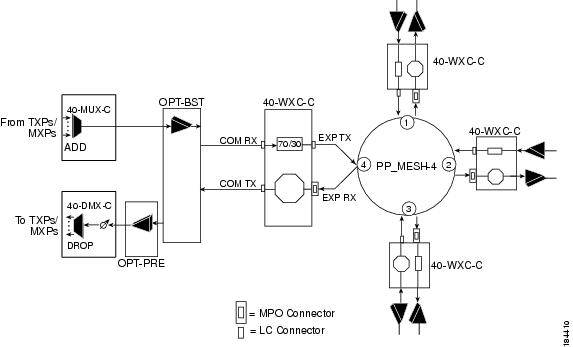
11.2.1 OPT-RAMP-C or OPT-RAMP-CE Card in an Add/Drop Node
When the OPT-RAMP-C or OPT-RAMP-CE card is equipped in an add/drop node, the booster amplifier is mandatory and cannot be replaced by an OSC-CSM card. The preamplifier is an OPT-BST, OPT-BST-E, or OPT-AMP-C card, and must be cabled as an unidirectional card. Note that the COM-TX and LINE-RX ports must not be used for any other connections. If a single module ROADM 40-SMR-1-C is used as an add/drop card, a preamplifier is not required. If a single module ROADM 40-SMR-2-C is used as an add/drop card, both the preamplifier and booster are not required.
Figure 11-33 shows the OPT-RAMP-C or OPT-RAMP-CE card in an add/drop node.
Figure 11-33 OPT-RAMP-C or OPT-RAMP-CE Card in an Add/Drop Node
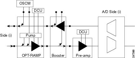
When required, a DCN extension can be used on A/D Side (i) in Figure 11-33.
Side (i) in Figure 11-33 can be equipped with the following cards:
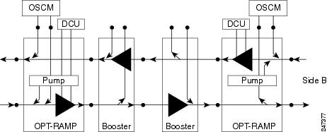
11.2.2 OPT-RAMP-C or OPT-RAMP-CE Card in a Line Site Node with Booster Amplification
The OPT-RAMP-C or OPT-RAMP-CE card can be equipped in a line site node with a booster amplifier in the following configurations:
- OPT-BST and OPT-BST-E can be used as booster in a line site node with OPT-RAMP-C or OPT-RAMP-CE. The booster cards need to be cabled as bidirectional units. Figure 11-34 shows the OPT-RAMP-C or OPT-RAMP-CE card in a line site configuration.
Figure 11-34 OPT-RAMP-C Card or OPT-RAMP-CE Card in a Line Site Configuration
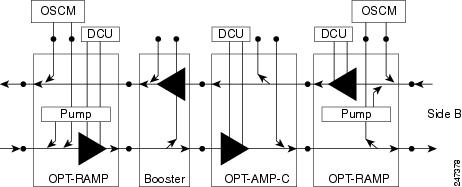
- The OPT-AMP-C can be used as a booster in a line site node with OPT-RAMP-C or OPT-RAMP-CE and needs to be cabled as a bidirectional unit. An additional DCU unit can be equipped between the OPT-AMP-C DC ports. Figure 11-35 shows a line site configured with OPT-AMP-C card and an additional DCU unit.
Figure 11-35 Line Site Configured with OPT-AMP-C
- A line site can be configured with OPT-RAMP-C or OPT-RAMP-CE card on one side only. Figure 11-36 shows the line site configured with OPT-RAMP-C or OPT-RAMP-CE on side A only. The booster is configured on side B.
Figure 11-36 Line Site with OPT-RAMP-C or OPT-RAMP-CE On One Side
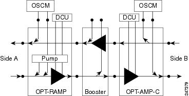
In all configurations, the booster amplifier facing the OPT-RAMP-C or OPT-RAMP-CE card is mandatory for safety reasons.
11.3 Supported Node Configurations for PSM Card
The PSM card supports the following node configurations:
11.3.1 Channel Protection
In a channel protection configuration, the PSM card is used in conjunction with a TXP/MXP card. The PSM card in a channel protection configuration can be used in any site apart from a terminal site.
Figure 11-37 shows the DWDM functional view of a PSM card in channel protection configuration.
Figure 11-37 PSM Channel Protection Configuration
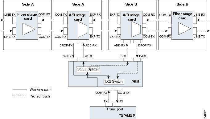
In this configuration, the COM-RX and COM-TX ports of the PSM card are connected to the TXP/MXP trunk ports. This configuration is applicable to an n -degree MSTP node, for example, a two-degree ROADM, an n -degree ROADM, or an OADM node. The example block diagram shows a two-degree node with Side A and Side B as the two sides. The Side A and Side B fiber-stage block can be DWDM cards that are used to amplify transmitted or received signal (see the “Fiber Stage” section for the list of cards). The Side A and Side B add/drop stage block can be DWDM cards that can add and drop traffic (see the “A/D Stage” section for the list of cards).
In the transmit direction, the traffic originating from a TXP/MXP trunk port is split by the PSM card on to the W-TX and P-TX ports. The W-TX and P-TX ports are connected to the ADD-RX ports of the add/drop stage cards in Side A and Side B respectively. The add/drop stage cards multiplex traffic on Side A and Side B line ports that become the working and protect paths respectively.
In the receive direction, the W-RX and P-RX ports of the PSM card are connected to the DROP-TX ports of the add/drop stage cards on Side A and Side B respectively. The add/drop stage cards demultiplex traffic received from Side A and Side B line ports that are the working and protect paths respectively. The PSM card selects one of the two input signals on the W-RX and P-RX ports to be transmitted to the COM-RX port of the PSM card.
Note![]() All traffic multiplexed or demultiplexed by the two add/drop stage cards is not protected.
All traffic multiplexed or demultiplexed by the two add/drop stage cards is not protected.
11.3.2 Multiplex Section Protection
The PSM card performs multiplex section protection when connected between a multiplexer/demultiplexer card in a terminal site. The multiplexer/demultiplexer stage can be built using WSS and DMX or 40MUX and 40DMX cards. The terminal sites can be 50/100 Ghz band. The number of supported channels can therefore be 32/40 or 72/80.
Figure 11-38 shows the block diagram of a PSM card in multiplex section protection configuration.
Figure 11-38 PSM Multiplex Section Protection Configuration
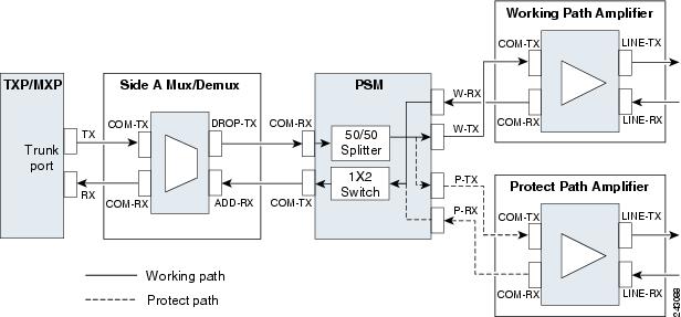
In the transmit direction, the traffic originating from a TXP trunk port is multiplexed by the Side A multiplexer. The PSM card splits traffic on to the W-TX and P-TX ports, which are independently amplified by two separated booster amplifiers.
In the receive direction, the signal on the line ports is preamplified by two separate preamplifiers and the PSM card selects one of the two input signals on the W-RX and P-RX ports to be transmitted to the COM-RX port of the PSM card. The received signal is then demultiplexed to a TXP card.
The presence of a booster amplifier is not mandatory. However, if a DCN extension is used, the W-TX and P-TX ports of the PSM card can be connected directly to the line. The presence of a preamplifier is also not mandatory.
Note![]() The PSM card cannot be used with Raman amplification in a line protection or section protection configuration.
The PSM card cannot be used with Raman amplification in a line protection or section protection configuration.
11.3.3 Line Protection
In a line protection configuration, the working and protect ports of the PSM card are connected directly to the external line. This configuration is applicable to any MSTP node that is configured as a terminal site. The multiplexer/demultiplexer stage can be built using WSS and DMX, 40MUX and 40DMX, 40-SMR1-C and 15216-MD-40-ODD, 15216-EF-40-ODD, or 15216-MD-48-ODD, or 40-SMR2-C and 15216-MD-40-ODD, 15216-EF-40-ODD, or 15216-MD-48-ODD units. The terminal sites can be 50/100 Ghz band. The number of supported channels can therefore be 32/40 or 72/80.
Figure 11-39 shows the block diagram of a PSM card in line protection configuration.
Figure 11-39 PSM Line Protection Configuration
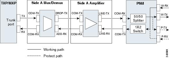
In the transmit direction, the traffic originating from a transponder trunk port is multiplexed by the Side A multiplexer and amplified by a booster amplifier. The Line-TX port of the amplifier is connected to the COM-RX port of the PSM card. The PSM card splits traffic received on the COM-RX port on to the W-TX and P-TX ports, which form the working and protect paths.
In the receive direction, the PSM card selects one of the two input signals on the W-RX and P-RX ports to be transmitted to the COM-RX port of the PSM card. The received signal is then preamplified and demultiplexed to the TXP card.
The presence of a booster amplifier is not mandatory. However, if a DCN extension is used, the COM-RX port of the PSM card is connected to the multiplex section. The presence of a preamplifier is also not mandatory; the COM-TX port of the PSM card can be connected to the demultiplexer.
Note![]() The PSM card cannot be used with Raman amplification in a line protection or section protection configuration.
The PSM card cannot be used with Raman amplification in a line protection or section protection configuration.
11.3.4 Standalone
In a standalone configuration, the PSM card can be equipped in any slot and supports all node configurations. In this configuration, the PSM card provides only basic functionality, such as, protection against a fiber cut, optical safety, and automatic laser shutdown (ALS). It does not provide other functionalities such as, automatic power control (APC), automatic node setup (ANS), network and node alarm correlation, circuit management, and so on.
11.4 Multishelf Node
In a multishelf configuration, the ONS 15454-M6 node or the ONS 15454-DWDM node with TCC3 card as the node controller can manage up to 29 subtending shelves as a single entity. The subtending shelves can be 15454-M6 or 15454-DWDM.
The node controller is the main shelf with the TCC2/TCC2P/TCC3/TNC/TNCE/TSC/TSCE cards running the multishelf functions. Each subtending shelf must be equipped with TCC2/TCC2P/TCC3/TNC/TNCE/TSC/TSCE cards, which run the shelf functions. For internal data exchange between the node controller shelf and subtending shelves, the node controller shelf must be equipped with redundant MS-ISC-100T cards or, as an alternative, the Catalyst 2950 switch. We recommend that you use the MS-ISC-100T cards. If using the Catalyst 2950, it is installed on one of the multishelf racks. All subtending shelves must be located in the same site at a maximum distance of 100 meters or 328 feet from the Ethernet switches used to support the communication LAN. Figure 11-40 shows an example of a multishelf node configuration.
Figure 11-40 Multishelf Node Configuration
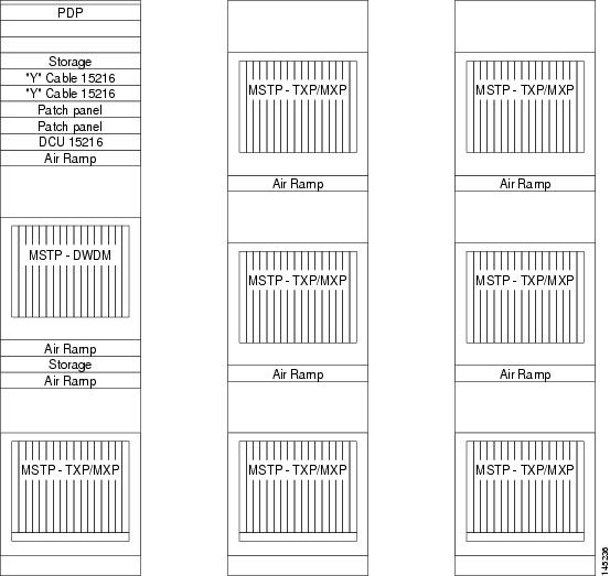
A multishelf node has a single public IP address for all client interfaces (Cisco Transport Controller [CTC], Transaction Language One [TL1], Simple Network Management Protocol [SNMP], and HTTP); a client can only connect to the node controller shelf, not to the subtending shelves. The user interface and subtending shelves are connected to a patch panel using straight-through (CAT-5) LAN cables.
The node controller shelf has the following functions:
- IP packet routing and network topology discovery at the node controller level.
- Open Shortest Path First (OSPF) centralized on the node controller shelf.
The subtending shelves have the following functions:
- Overhead circuits are not routed within a multishelf node but are managed at the subtending controller shelf only. To use overhead bytes, the AIC-I must be installed on the subtending shelf where it is terminated.
- Each subtending shelf will act as a single shelf node that can be used as a timing source line, TCC/TCC2P/TCC3/TNC/TSC clock, or building integrated timing supply (BITS) source line.
11.4.1 Multishelf Node Layout
Multishelf configurations are configured by Cisco TransportPlanner and are automatically discovered by the CTC software. In a typical multishelf installation, all optical units are equipped on the node controller shelf and TXP/MXP cards are equipped in the aggregated subtended shelves. In addition, all empty slots in the node controller shelf can be equipped with TXP/MXP cards. In a DWDM mesh network, up to eight optical sides can be configured with client and optical cards installed in different shelves to support mesh and ring-protected signal output.
Note![]() When a DWDM ring or network has to be managed through a Telcordia operations support system (OSS), every node in the network must be set up as multi-shelf. OLA sites and nodes with one shelf must be set up as "multi-shelf stand-alone" to avoid the use of LAN switches.
When a DWDM ring or network has to be managed through a Telcordia operations support system (OSS), every node in the network must be set up as multi-shelf. OLA sites and nodes with one shelf must be set up as "multi-shelf stand-alone" to avoid the use of LAN switches.
11.4.2 DCC/GCC/OSC Terminations
A multishelf node provides the same communication channels as a single-shelf node:
- OSC links terminate on OSCM/OSC-CSM cards. Two links are required between each ONS 15454 node. An OSC link between two nodes cannot be substituted by an equivalent generic communications channel/data communications channel (GCC/DCC) link terminated on the same pair of nodes. OSC links are mandatory and they can be used to connect a node to a gateway network element (GNE).
- GCC/DCC links terminate on TXP/MXP cards.
The maximum number of DCC/GCC/OSC terminations that are supported in a multishelf node is 48.
Note![]() Optical Service Channel can be created on the OC3 port of the TNC card.
Optical Service Channel can be created on the OC3 port of the TNC card.
11.5 Optical Sides
From a topological point of view, all DWDM units equipped in an MSTP node belongs to a side. A side can be identified by a letter (A, B, C, D, E, F, G, or H), or by the ports (called as side line ports, see Side Line Ports) that are physically connected to the spans. An MSTP node can be connected to a maximum of 8 different spans. Each side identifies one of the spans the MSTP node is connected to.
Note![]() Side A and Side B replace “west” and “east” when referring to the two sides of the ONS 15454 shelf. Side A refers to Slots 1 through 6 (formerly “west”), and Side B refers to Slots 12 through 17 (formerly “east”). The line direction port parameter, East-to-West and West-to-East, has been removed.
Side A and Side B replace “west” and “east” when referring to the two sides of the ONS 15454 shelf. Side A refers to Slots 1 through 6 (formerly “west”), and Side B refers to Slots 12 through 17 (formerly “east”). The line direction port parameter, East-to-West and West-to-East, has been removed.
Sides are viewed and managed from the Provisioning > WDM-ANS > Optical Sides tab in CTC.
11.5.1 Optical Side Stages
All MSTP nodes can be modelled according to Figure 11-41.
Figure 11-41 Interconnecting Sides Conceptual View
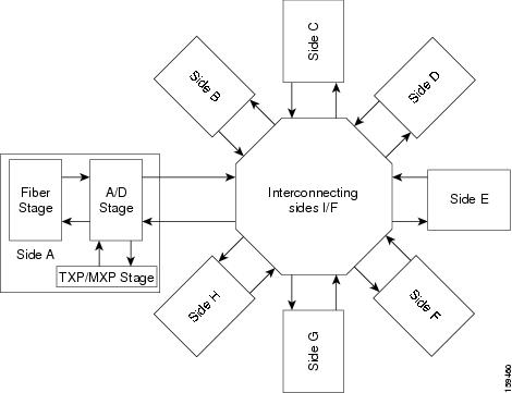
According to Figure 11-41, each MSTP node side includes DWDM units that can be conceptually divided into three stages.
11.5.1.1 Fiber Stage
The fiber stage includes DWDM cards that are used to amplify transmitted or received signals and cards that are used to add optical supervision channels. The fiber stage cards are:
–![]() OPT-AMP-C, when provisioned in OPT-LINE (booster amplifier) mode
OPT-AMP-C, when provisioned in OPT-LINE (booster amplifier) mode
–![]() OPT-AMP-L, when provisioned in OPT-LINE (booster amplifier) mode
OPT-AMP-L, when provisioned in OPT-LINE (booster amplifier) mode
–![]() OPT-AMP-17-C, when provisioned in OPT-LINE (booster amplifier) mode
OPT-AMP-17-C, when provisioned in OPT-LINE (booster amplifier) mode
–![]() OPT-AMP-C, when provisioned in OPT-PRE (preamplifier) mode
OPT-AMP-C, when provisioned in OPT-PRE (preamplifier) mode
–![]() OPT-AMP-L, when provisioned in OPT-PRE (preamplifier) mode
OPT-AMP-L, when provisioned in OPT-PRE (preamplifier) mode
–![]() OPT-AMP-17-C, when provisioned in OPT-PRE (preamplifier) mode
OPT-AMP-17-C, when provisioned in OPT-PRE (preamplifier) mode
Table 11-1 shows the commonly deployed fiber stage layouts supported by DWDM mesh nodes. In the table, OPT-BST includes the OPT-BST, OPT-BST-E, and OPT-BST-L cards. OPT-AMP includes the OPT-AMP-L and OPT-AMP-17-C cards configured in either OPT-PRE or OPT-LINE mode.
Note![]() In the table, L and C suffix is not reported because C-band and L-band amplifiers cannot be mixed in the same layout.
In the table, L and C suffix is not reported because C-band and L-band amplifiers cannot be mixed in the same layout.
11.5.1.2 A/D Stage
The A/D stage includes DWDM cards that can add and drop traffic. The A/D stage is divided into three node types:
- Mesh nodes—ONS 15454 nodes configured in multishelf mode can connect to eight different sides. For more detail on mesh node, see Configuring Mesh DWDM Networks.
- Legacy—Half of a ROADM node or an OADM node with cascaded AD-xB-xx-x or AD-xC-xx.x cards
- Non-A/D—A line node or a side that does not have A/D capability is included in the A/D stage
Stages are built by active cards and patchcords. However, the interconnecting sides are completed by the mesh patch panels (four-degree patch panel or eight-degree patch panel) in mesh nodes, or by patchcords connected to EXP-RX/EXP-TX ports in legacy nodes.
11.5.2 Side Line Ports
Side line ports are ports that are physically connected to the spans. Side line ports can be:
- All ports terminating the fiber stage and physically labeled as LINE, such as ports on the following cards:
–![]() Booster amplifier (OPT-BST, OPT-BST-E, or OPT-BST-L cards, and the OPT-AMP-C, OPT-AMP-L, or OPT-AMP-17-C cards when provisioned in OPT-LINE mode)
Booster amplifier (OPT-BST, OPT-BST-E, or OPT-BST-L cards, and the OPT-AMP-C, OPT-AMP-L, or OPT-AMP-17-C cards when provisioned in OPT-LINE mode)
–![]() Booster amplifier LINE-RX and LINE-TX ports
Booster amplifier LINE-RX and LINE-TX ports
–![]() OSC-CSM LINE-RX and LINE-TX ports
OSC-CSM LINE-RX and LINE-TX ports
–![]() 40-WXC-C COM-RX and COM-TX ports
40-WXC-C COM-RX and COM-TX ports
–![]() MMU EXP-A-RX and EXP-A-TX ports
MMU EXP-A-RX and EXP-A-TX ports
- All ports that can be physically connected to the external span using DCN terminations in a line node, such as:
–![]() Preamplifier (OPT-PRE card and the OPT-AMP-C, OPT-AMP-L, or OPT-AMP-17-C cards when provisioned in OPT-PRE mode) COM-RX and COM-TX ports
Preamplifier (OPT-PRE card and the OPT-AMP-C, OPT-AMP-L, or OPT-AMP-17-C cards when provisioned in OPT-PRE mode) COM-RX and COM-TX ports
–![]() Booster amplifier COM-TX port
Booster amplifier COM-TX port
- All ports that can be physically connected to the external span using DCN terminations in a 40-channel MUX/DMX terminal node, such as:
- All ports that can be physically connected to the external span when PSM cards implement line protection:
Note![]() PSM card will support two sides A(w) and A(p).
PSM card will support two sides A(w) and A(p).
11.5.3 Optical Side Configurations
You can use the following Side IDs depending on the type of node layout:
- In legacy nodes (that is, a node with no provisioned or installed 40-WXC-C cards), the permissible Side IDs are only A and B.
- In four-degree mesh nodes with four or less 40-WXC-C cards installed, the permissible Side IDs are A, B, C, and D.
- In eight-degree mesh nodes with eight or less 40-WXC-C cards installed, the allowed Side IDs are A, B, C, D, E, F, G, and H.
The system automatically assigns Side IDs when you import the CTP XML configuration file into CTC. You can create a side manually using CTC or TL1 if the following conditions are met:
- You use a permissible side identifier, A through H.
- The shelf contains a TX and an RX side line port (see the “Side Line Ports” section).
- The side line ports are not connected to an internal patchcord.
Note![]() We do not recommend that you manually create or modify ONS 15454 optical sides.
We do not recommend that you manually create or modify ONS 15454 optical sides.
The following tables show examples of how the system automatically assigns Side IDs for common DWDM layouts.
Table 11-2 shows a standard ROADM shelf with Sides A and B provisioned. The shelf is connected to seven shelves containing TXP, MXP, ADM-10G, GE_XP, 10GE_XP, GE_XPE, and 10GE_XPE cards.
|
|
|
|
|
|
|---|---|---|---|---|
Table 11-3 shows a protected ROADM shelf. In this example, Side A and B are Slots 1 through 6 in Shelves 1 and 2. 40-WSS-C/40-WSS-CE/40-DMX-C or 40-WSS-CE/40-DMX-CE cards are installed in Sides A and B. Slots 12 through 17 in Shelves 1 and 2 contain TXP, MXP, ADM-10G, GE_XP, 10GE_XP, GE_XPE, or 10GE_XPE cards.
|
|
|
|
|
|
|---|---|---|---|---|
Table 11-4 shows a four-degree mesh node. Side A is Shelf 1, Slots 1 through 6. Side B and C are Shelf 2, Slots 1 through 6 and 12 through 17, and Side D is Shelf 3, Slots 1 through 6. 40-WXC-C cards in line termination mode are installed in Sides A through D.
|
|
|
|
|
|
|---|---|---|---|---|
Table 11-5 shows a protected four-degree mesh node example. In the example, Sides A through D are assigned to Slots 1 through 6 in Shelves 1 through 4.
|
|
|
|
|
|
|---|---|---|---|---|
Table 11-6 shows a protected four-degree mesh node example. In the example, Sides A through D are assigned to Slots 1 through 4 in Shelves 1 through 4, and TXP, MXP, ADM-10G, GE_XP, 10GE_XP, GE_XPE, or 10GE_XPE cards are installed in Shelves 1 through 4, Slots 12-17, and Shelves 5 through 8, Slots 1 through 6 and 12 through 17.
|
|
|
|
|
|
|---|---|---|---|---|
Table 11-7 shows a four-degree mesh node provisioned as an upgrade. In the example, Sides A through D are assigned to Slots 1 through 4. and 12 through 17 in Shelves 1and 2. 40-WXC-C cards in XC termination mode are installed in Sides A and B, and 40-WXC-C cards in line termination mode are installed in Sides C and D.
|
|
|
|
|
|
|---|---|---|---|---|
Table 11-8 shows an eight-degree mesh node. In the example, Sides A through H are assigned to Slots 1 through 6 in Shelf 1, Slots 1 through 6 and 12 through 17 in Shelves 2 through 4, and Slots 1 through 6 in Shelf 5. 40-WXC-C cards in line termination mode are installed in Sides A through H.
|
|
|
|
|
|
|---|---|---|---|---|
Table 11-9 shows another eight-degree mesh node. In the example, Sides A through H are assigned to Slots 1 through 6 in all shelves (Shelves 1 through 8). 40-WXC-C cards in line termination mode are installed in Sides A through H.
|
|
|
|
|
|
|---|---|---|---|---|
Table 11-10 shows a four-degree mesh node with a user-defined side. Because the software assigns sides consecutively, and because the mesh node is four-degrees, the side assigned to Shelf 5, Slots 1 through 6 is “Unknown.”
|
|
|
|
|
|
|---|---|---|---|---|
C1 |
||||
U2 |
||||
|
|
11.6 Configuring Mesh DWDM Networks
ONS 15454 shelves can be configured in mesh DWDM networks using the 40-WXC-C or 80-WXC-C wavelength cross-connect cards and four-degree patch panel or eight-degree patch panels. Mesh DWDM networks can also be configured using the 40-SMR2-C cards and the four-degree patch panel.
ONS 15454 DWDM mesh configurations can be up to four degrees (four optical directions) when the four-degree patch panel is installed, and up to eight degrees (eight optical directions) when the eight-degree patch panel is installed. Two mesh node types are available, the line termination mesh node and the cross-connect (XC) termination mesh node.
Note![]() Mesh nodes using the 40-WXC-C or 80-WXC-C card requires multishelf management.
Mesh nodes using the 40-WXC-C or 80-WXC-C card requires multishelf management.
11.6.1 Line Termination Mesh Node Using 40-WXC-C Cards
The line termination mesh node is installed in native Software Release 9.2 mesh networks. Line termination mesh nodes can support between one and eight line terminations. Each line direction requires the following cards: 40-WXC-C, 40-MUX-C, 40-DMX-C or 40-DMX-CE, a preamplifier and a booster. Within this configuration, the following substitutions can be used:
- The 40-MUX-C cards can be replaced with 40-WSS-C/40-WSS-CE cards.
- The OPT-BST cards can be replaced with OPT-AMP-17-C (in OPT-BST mode) and/or OPT-BST-E cards.
- The OPT-PRE can be replaced with an OPT-AMP-17-C (in OPT-LINE mode) card.
Each side of the line termination mesh node is connected as follows:
- The 40-WXC-C COM-RX port is connected to the preamplifier output port.
- The 40-WXC-C COM-TX port is connected to the booster amplifier COM-RX port.
- The 40-WXC-C DROP TX port is connected to the 40-DMX-C or 40-DMX-CE COM-RX port.
- The 40-WXC-C ADD-RX port is connected to the 40-MUX-C COM-TX port.
- The 40-WXC-C EXP-TX port is connected to the mesh patch panel.
- The 40-WXC-C EXP-RX port is connected to the mesh patch panel.
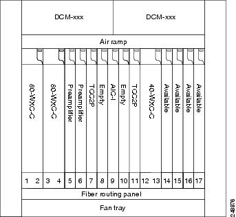
Figure 11-42 shows one shelf from a line termination node.
Figure 11-42 Line Termination Mesh Node Shelf
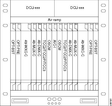
Figure 11-43 shows a functional block diagram of one line termination side using 40-WXC-C and 40-MUX-C cards.
Figure 11-43 Line Termination Mesh Node Side—40-MUX-C Cards
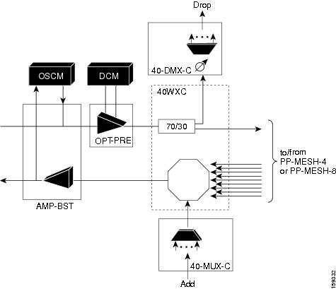
Figure 11-44 shows a functional block diagram line termination side using 40-WXC-C and 40-WSS-C cards.
Figure 11-44 Line Termination Mesh Node Side—40-WSS-C Cards
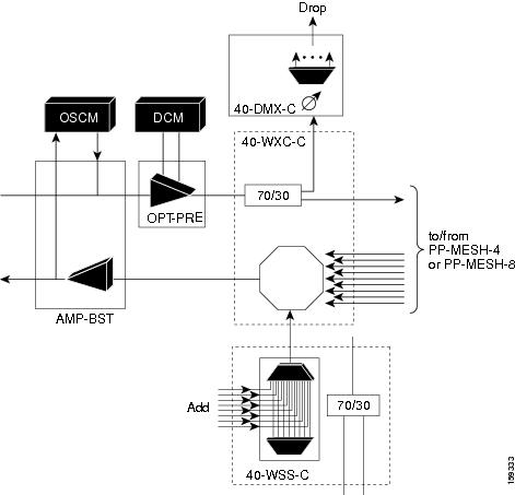
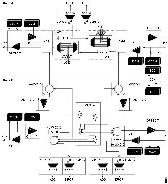
Figure 11-45 shows a functional block diagram of a node that interconnects a ROADM with MMU cards with two native line termination mesh sides.
Figure 11-45 Line Termination Mesh Nodes—ROADM With MMU Cards
11.6.1.1 40-Channel Omni-directional n-degree ROADM Node
Any side in the line termination mesh node can be configured as an omni-directional side. The side that is configured as the omni-directional side is connected to a local multiplexer and demultiplexer that can add or drop traffic to or from any of the node directions.
In Figure 11-46 side D is configured as the omni-directional side. Wavelengths from the local multiplexer on side D is routed to sides A, B, or C by the patch panel. Wavelengths from sides A, B, or C can be dropped on side D. The maximum number of omni-directional channels is 40.
Figure 11-46 40-Channel Omni-directional Four-Degree ROADM Node
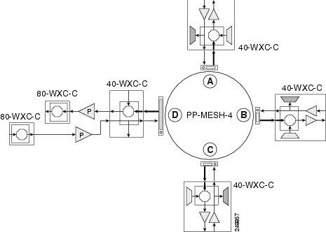
11.6.1.2 40-Channel Colorless n-Degree ROADM Node
Any side in the line termination mesh node can be configured as a colorless side where any wavelength can be added or dropped. The side that is configured as the colorless side is connected to two 80-WXC-C cards configured as a multiplexer and demultiplexer respectively. In Figure 11-47 side D is configured as the colorless side. The 80-WXC-C cards are connected to the add and drop ports of the 40-WXC-C cards and function as a colorless multiplexer and demultiplexer.
A combination of wavelengths from any of the nine ports is sent to the common output port of the 80-WXC-C card (multiplexer) that is connected to the 40-WXC-C card. The wavelengths entering the 40-WXC-C card are sent to the common input port of the 80-WXC-C card (demultiplexer) and dropped at any of the nine output ports.
Figure 11-47 40-Channel Colorless Four-Degree ROADM Node
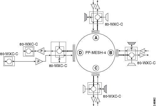
11.6.1.3 40-Channel Colorless and Omni-directional n-Degree ROADM Node
Any side in the line termination mesh node can be configured as a colorless and omni-directional side. The side that is configured as the colorless and omni-directional side is connected to a multiplexer (80-WXC-C) and demultiplexer (80-WXC-C) that can add or drop traffic to or from any of the node directions.
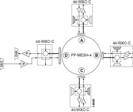
Figure 11-48 shows the layout of a 40-channel n-degree ROADM node with colorless and omni-directional side.
Figure 11-48 40-Channel n-Degree ROADM Node with Colorless and Omni-directional Side
In Figure 11-49 side D is configured as the colorless and omni-directional side.
A combination of wavelengths from any of the nine ports is sent to the common output port of the 80-WXC-C card (multiplexer) and then routed to the preamplifier. The preamplifier sends the wavelengths to the 40-WXC-C card that is connected to the patch panel. The patch panel routes the wavelengths to sides A, B, or C.
Wavelengths from sides A, B, or C are dropped on side D. The incoming wavelengths from the 40-WXC-C card are sent to the preamplifier. The preamplifer amplifies the signal and sends it to the common input port of the 80-WXC-C card (demultiplexer). The wavelengths are then dropped at any of the nine output ports.
Figure 11-49 40-Channel Colorless and Omni-directional Four-Degree ROADM Node
11.6.2 Line Termination Mesh Node Using 80-WXC-C Cards
Line termination mesh nodes using 80- WXC-C cards can support between one and eight line terminations. Each line direction requires the following units: 80-WXC-C, 15216-MD-40-ODD, 15216-EF-40-ODD, or 15216-MD-48-ODD, and 15216-MD-40-EVEN, 15216-EF-40-EVEN, or 15216-MD-48-EVEN, 15216-MD-ID-50 or 15216-MD-48-CM, a preamplifier, and a booster.
- The OPT-BST cards can be replaced with OPT-AMP-17-C (in OPT-BST mode) or OPT-BST-E cards.
- The OPT-PRE can be replaced with an OPT-AMP-17-C (in OPT-LINE mode) card.
Each side of the line termination mesh node is connected as follows:
- The 80-WXC-C COM-RX port is connected to the preamplifier output port.
- The 80-WXC-C COM port is connected to the booster amplifier COM-RX port.
- The 80-WXC-C DROP TX port is connected to the COM-RX (ODD+EVEN-RX) port of 15216-MD-ID-50 or 15216-MD-48-CM. The ODD-TX port of the 15216-MD-ID-50 or 15216-MD-48-CM is connected to the COM-RX port of 15216-MD-40-ODD, 15216-EF-40-ODD, or 15216-MD-48-ODD; and the EVEN-TX port of the 15216-MD-ID-50 or 15216-MD-48-CM is connected to the COM-RX port of 15216-MD-40-EVEN, 15216-EF-40-EVEN, or 15216-MD-48-EVEN.
- The 80-WXC-C AD port is connected to the COM-TX (ODD+EVEN-TX) port of 15216-MD-ID-50 or 15216-MD-48-CM. The ODD-RX port of the 15216-MD-ID-50 or 15216-MD-48-CM is connected to the COM-TX port of 15216-MD-40-ODD, 15216-EF-40-ODD, or 15216-MD-48-ODD; and the EVEN-RX port of the 15216-MD-ID-50 or 15216-MD-48-CM is connected to the COM-TX port of 15216-MD-40-EVEN, 15216-EF-40-EVEN, or 15216-MD-48-EVEN.
- The 80-WXC-C EXP-TX port is connected to the mesh patch panel.
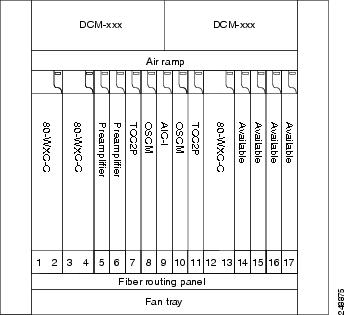
Figure 11-50 shows the layout for a line termination node.
Figure 11-50 Line Termination Node
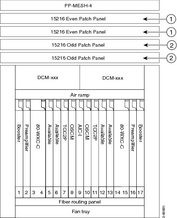
|
|
|
|
|
|
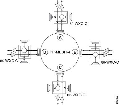
Figure 11-51 shows the functional block diagram of a four-degree line termination mesh node using 80-WXC-C, 15216-MD-40-ODD, 15216-EF-40-ODD, 15216-MD-48-ODD, 15216-MD-40-EVEN, 15216-EF-40-EVEN, or 15216-MD-48-EVEN. All the 80-WXC-C cards are in bidirectional mode. Wavelengths entering from side(i) can be routed to any of the other n-1 sides where n is defined by the PP MESH type.
Figure 11-51 Four-Degree Line Termination Mesh Node Functional Diagram
11.6.2.1 80-Channel Omni-directional n-degree ROADM Node
Any side in the line termination mesh node can be configured as a omni-directional side. The side that is configured as the omni-directional side is connected to a local multiplexer and demultiplexer that can add or drop traffic to or from any of the node directions.
In Figure 11-52, side D is configured as the omni-directional side. Wavelengths from the local multiplexer on side D are routed to sides A, B, or C by the patch panel. Wavelengths from sides A, B, or C are dropped on side D.
Figure 11-52 80-Channel Omni-directional Four-Degree ROADM Node
11.6.2.2 80-Channel Colorless n-degree ROADM Node
Any side in the line termination mesh node can be configured as a colorless side where any wavelength can be added or dropped. The side that is configured as the colorless side is connected to two 80-WXC-C cards configured as a multiplexer and demultiplexer respectively. In Figure 11-53, side D is configured as the colorless side. The 80-WXC-C cards are connected to the add and drop ports of the 80-WXC-C cards as a colorless multiplexer and demultiplexer.
A combination of wavelengths from any of the nine ports is sent to the common output port of the 80-WXC-C card (multiplexer) that is connected to the 80-WXC-C card. The wavelengths entering the 80-WXC-C card is passed to the common input port of the 80-WXC-C card (demultiplexer) and dropped at any of the nine output ports.
Figure 11-53 80-Channel Colorless Four-Degree ROADM Node
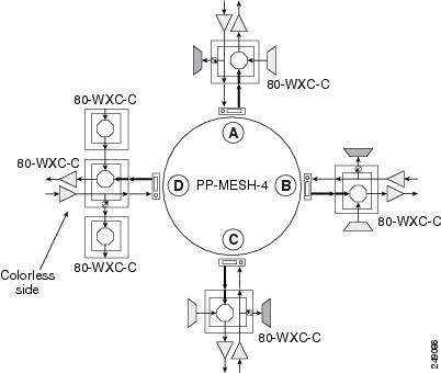
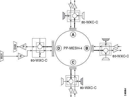
11.6.2.3 80-Channel Colorless and Omni-directional n-Degree ROADM Node
Any side in the line termination mesh node can be configured as a colorless and omni-directional side. The side that is configured as the colorless and omni-directional side is connected to a multiplexer (80-WXC-C) and demultiplexer (80-WXC-C) that can add or drop traffic to or from any of the node directions.
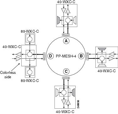
Figure 11-54 shows the layout of a 80-channel n-degree ROADM node with colorless and omnidirectional side.
Figure 11-54 80-Channel n-degree ROADM Node with Colorless and Omnidirectional Side
In Figure 11-55 side D is configured as the colorless and omni-directional side.
A combination of wavelengths from any of the nine ports is sent to the common output port of the 80-WXC-C card (multiplexer) and is then routed to the preamplifier. The preamplifier sends the wavelengths to the 80-WXC-C card that is connected to the patch panel. The patch panel routes the wavelengths to sides A, B, or C.
Wavelengths from sides A, B, or C can be dropped on side D. The incoming wavelengths from the 80-WXC-C card are sent to the preamplifier. The preamplifer amplifies the signal and sends it to the common input port of the 80-WXC-C card (demultiplexer). The wavelengths are then dropped at any of the nine output ports.
Figure 11-55 80-Channel Colorless and Omni-directional Four-Degree ROADM Node
11.6.3 Line Termination Mesh Node Using 40-SMR2-C Cards
Line termination mesh nodes using the 40-SMR2-C cards can support between one and four line terminations. Each line direction requires the 40-SMR2-C and 15216-MD-40-ODD, 15216-EF-40-ODD, or 15216-MD-48-ODD cards. Although it is recommended that you use the 15216-MD-40-ODD, 15216-EF-40-ODD, or 15216-MD-48-ODD card along with the 40-SMR2-C card, you can alternatively use the 40-MUX-C and 40-DMX-C cards instead of the 15216-MD-40-ODD, 15216-EF-40-ODD, or 15216-MD-48-ODD card.
Each side of the line termination mesh node is connected as follows:
- The 40-SMR2-C LINE-RX port is connected to the external line.
- The 40-SMR2-C LINE-TX port is connected to the external line.
- The 40-SMR2-C DROP TX port is connected to the 15216-MD-40-ODD, 15216-EF-40-ODD, or 15216-MD-48-ODD (or 40-DMX-C) COM-RX port.
- The 40-SMR2-C ADD-RX port is connected to the 15216-MD-40-ODD, 15216-EF-40-ODD, or 15216-MD-48-ODD (or 40-DMX-C) COM-TX port.
- The 40-SMR2-C EXP-TX port is connected to the mesh patch panel.
- The 40-SMR2-C EXP i -RX (where i = 1, 2, 3) port is connected to the mesh patch panel.
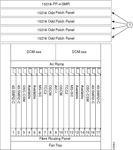
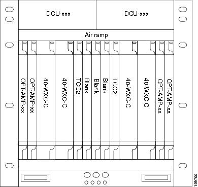
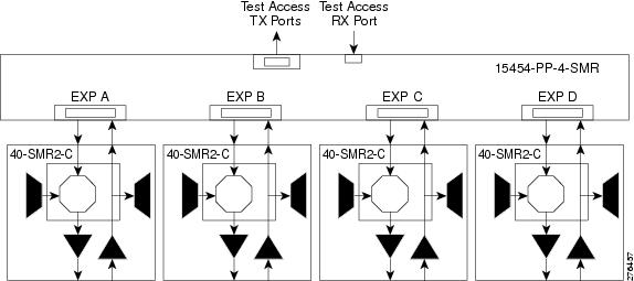
Figure 11-56 shows the layout for a line termination node.
Figure 11-56 Line Termination Mesh Node Shelf
|
|
|
Figure 11-57 shows the functional block diagram of a four-degree line termination mesh node using 40-SMR2-C, 15216-MD-40-ODD, 15216-EF-40-ODD, or 15216-MD-48-ODD, and 15454-PP-4-SMR patch panel.
Figure 11-57 Four-Degree Line Termination Mesh Node Functional Diagram
11.6.4 XC Termination Mesh Node
The XC termination mesh node, shown in Figure 11-58, is the second mesh node type. It is used to upgrade a non-mesh node to a mesh node or to interconnect two non-mesh nodes. The XC termination mesh nodes contain the following cards:
The XC termination mesh node is connected as follows:
- The 40-WXC-C COM-RX port is connected to the MMU EXP-A-TX port.
- The 40-WXC-C COM-TX port is connected to the MMU EXP-A-RX port.
- The 40-WXC-C EXP-TX port is connected to the OPT-AMP-17-C COM-RX port.
- The 40-WXC-C EXP-RX port is connected to the OPT-AMP-17-C COM-TX port.
- The 40-WXC-C EXP-TX port is connected to the mesh patch panel.
- The 40-WXC-C EXP-RX port is connected to the mesh patch panel.
Figure 11-58 XC Termination Mesh Node Shelf
11.6.5 Mesh Patch Panels and Shelf Layouts
ONS 15454 mesh topologies require the installation of a four-degree patch panel, PP-MESH-4 (for 40-WXC-C cards) or 15454-PP-4-SMR (for 40-SMR2-C cards) or an eight-degree patch panel, PP-MESH-8 (for 40-WXC-C cards). If the four-degree patch panel is installed, mesh topologies of up to four degrees can be created. If the eight-degree patch panel is installed, mesh topologies of up to eight degrees can be created. The four-degree patch panel contains four 1x4 optical splitters, and the eight-degree patch panel contains eight 1x8 splitters. Each mesh patch panel contains a 2x8 splitter that is used for the test access transmit and receive ports. Figure 11-59 shows a block diagram for the PP-MESH-4 patch panel.
Figure 11-59 PP-MESH-4 Patch Panel Block Diagram
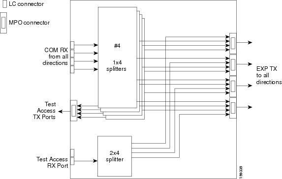
At the mesh patch panel, the signal is split into four signals (if a four-degree patch panel is used) or eight signals (if an eight-degree patch panel is used). Figure 11-60 shows the signal flow at the four-degree PP-MESH-4 patch panel. 40-WXC-C cards connect to the four-degree patch panel at the EXP TX and COM RX ports.
Figure 11-60 PP-MESH-4 Patch Panel Signal Flow
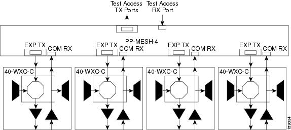
The mesh patch panels interconnect 40-WXC-C cards to create mesh networks, including four-degree and eight-degree mesh topologies. In addition, shelves with 40-WXC-C cards can be configured with mesh patch panels to create multiring, MMU-based mesh nodes. 40-WXC-C cards can be installed in ROADM nodes with MMU cards to upgrade a two-degree MMU-based ROADM node into four-degree or eight-degree mesh nodes.
Figure 11-61 shows the block diagram of the four-degree 15454-PP-4-SMR patch panel connected to one 40-SMR2-C card. The 40-SMR2-C cards connect to the 15454-PP-4-SMR patch panel at the EXP RX ports.
Figure 11-61 15454-PP-4-SMR Patch Panel Block Diagram
You can use the 15454-PP-4-SMR patch panel to connect upto four 40-SMR2-C cards in a four-degree mesh node. The optical splitters inside the patch panel forward the output signal (EXP-TX port) of the 40-SMR2-C card on each side of the mesh node to the input port of the 40-SMR2-C cards on the other three sides of the mesh node. The 4x1 WXC block inside the 40-SMR2-C card selects which wavelength from which side must be propagated at the output of each side. Figure 11-60 shows the signal flow at the four-degree 15454-PP-4-SMR patch panel. 40-SMR2-C cards connect to the four-degree patch panel at the EXP-TX and EXP-RX ports.
Figure 11-62 15454-PP-4-SMR Patch Panel Signal Flow
11.6.6 Using a Mesh Node With Omni-Directional Add/Drop Section
Normally, multidegree mesh node use four or eight 40-WXC-C cards and a four-degree or eight-degree patch panel. Each of the 40-WXC-C cards uses a 40-MUX-C card to add wavelengths going to the span and a 40-DMX-C card to drop wavelengths coming in from the span. The 40-MUX-C and 40-DMX-C cards are connected to only one of the node directions. These cards can add/drop traffic only to/from the side that is associated to the 40-WXC-C card. The omni-directional configuration allows you to install a local multiplexer/demultiplexer that can add/drop traffic to/from any of the node directions. Figure 11-63 shows an example of how to set up a omni-directional add/drop configuration.
By setting up a NE as shown in the figure, it is possible to connect the transmit ports of TXP or MXP cards to a 40-MUX-C card and then connect the output of the 40-MUX-C card to an OPT-BST card. The OPT-BST card then connects to a preferred 40-WXC-C card in the four-degree or eight-degree ROADM node (40-WXC-C connected to port 4 of PP-MESH-4, as shown in the figure).
The patch panel splits the traffic coming from the OPT-BST card in all the node directions, through the software configuration. The wavelengths entering the 40-WXC-C cards (ports 1, 2, and 3) can be selectively sent out in any desired outbound direction. In the inbound direction, the patch panel on the preferred 40-WXC-C card, splits any of the wavelengths entering the NE through the 40-WXC-C cards (ports 1, 2, and 3). Through the software configuration, the wavelength can be passed to an OPT-PRE card or stopped. This whole configuration can be managed using a single IP address
An example of using a mesh node for omni-directional add/drop section is shown in Figure 11-63.
Figure 11-63 Mesh Node With Omni-Directional Add/Drop Section
11.7 DWDM Node Cabling
DWDM node cabling is specified by the Cisco TransportPlanner Internal Connections table. The following sections provide examples of the cabling that you will typically install for common DWDM node types.
Note![]() The cabling illustrations shown in the following sections are examples. Always install fiber-optic cables based on the Cisco TransportPlanner Internal Connections table for your site.
The cabling illustrations shown in the following sections are examples. Always install fiber-optic cables based on the Cisco TransportPlanner Internal Connections table for your site.
11.7.1 OSC Link Termination Fiber-Optic Cabling
OSC link termination cabling include the following characteristics:
- The OPT-BST and OSC-CSM cards are the only cards that directly interface with the line (span) fiber.
- The OSCM card only carries optical service channels, not DWDM channels.
- The OSCM and OSC-CSM cards cannot both be installed on the same side of the shelf (Side B or Side A). You can have different cards on each side, for example an OSCM card on Side A and an OSC-CSM card on Side B.
- When an OPT-BST card and an OSC-CSM card are both used on the same side of the node, the OPT-BST card combines the supervision channel with the DWDM channels and the OSC-CSM card acts as an OSCM card; it does not carry DWDM traffic.
- If an OPT-BST and an OSCM card are installed on Side B, the Side B OPT-BST OSC RX port is connected to the Side B OSCM TX port, and the Side B OPT-BST OSC TX port is connected to the Side B OSCM RX port.
- If an OPT-BST and an OSC-CSM card are installed on Side B, the Side B OPT-BST OSC RX port is connected to the Side B OSC-CSM LINE TX port, and the Side B OPT-BST OSC TX port is connected to the Side B OSC-CSM LINE RX port.
- If an OPT-BST and an OSCM card are installed on Side A, the Side A OPT-BST OSC TX port is connected to the Side A OSCM RX port, and the Side A OPT-BST OSC RX port is connected to the Side A OSCM TX port.
- If an OPT-BST and an OSC-CSM card are installed on Side A, the Side A OPT-BST OSC TX port is connected to the Side A OSC-CSM LINE RX port, and the Side A OPT-BST OSC RX port is connected to the Side A OSC-CSM LINE TX port.
Figure 11-64 shows an example of OSC fibering for a hub node with OSCM cards installed.
Figure 11-64 Fibering OSC Terminations—Hub Node with OSCM Cards
11.7.2 Hub Node Fiber-Optic Cabling
The following rules generally apply to hub node cabling:
- The Side A OPT-BST or OSC-CSM card common (COM) TX port is connected to the Side A OPT-PRE COM RX port or the Side A 32DMX-O/40-DMX-C/40-DMX-CE COM RX port.
- The Side A OPT-PRE COM TX port is connected to the Side A 32DMX-O/40-DMX-C/40-DMX-CE COM RX port.
- The Side A 32MUX-O/32WSS/32WSS-L COM TX port is connected to the Side A OPT-BST or Side A OSC-CSM COM RX port.
- The Side B 32MUX-O/32WSS/32WSS-L COM TX port is connected to the Side B OPT-BST or Side B OSC-CSM COM RX port.
- The Side B OPT-BST or Side B OSC-CSM COM TX port is connected to the Side B OPT-PRE COM RX port or the Side B 32DMX-O/32DMX COM RX port.
- The Side B OPT-PRE COM TX port is connected to the Side B 32DMX-O/32DMX COM RX port.
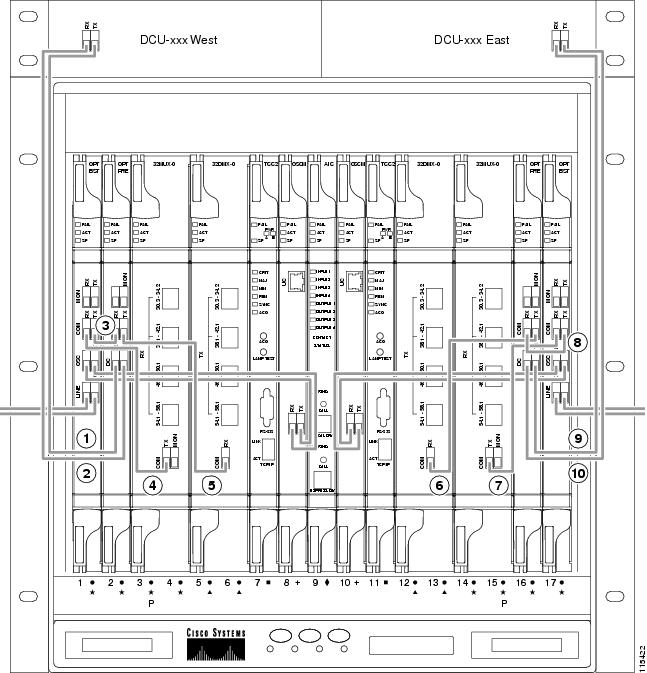
Figure 11-65 shows an example of a hub node with cabling. In the example, OSCM cards are installed. If OSC-CSM cards are installed, they are usually installed in Slots 1 and 17.
Figure 11-65 Fibering a Hub Node
|
|
Side A DCU TX to Side A OPT-PRE DC RX3 |
|
|
|
|
|
||
|
|
|
||
|
|
|
||
|
|
|
|
3.If a DCU is not installed, a 4-dB attenuator loop, +/– 1 dB must be installed between the OPT-PRE DC ports. |
11.7.3 Terminal Node Fiber-Optic Cabling
The following rules generally apply to terminal node cabling:
- A terminal site has only one side (as compared to a hub node, which has two sides). The terminal side can be either Side B or Side A.
- The terminal side OPT-BST or OSC-CSM card COM TX port is connected to the terminal side OPT-PRE COM RX port or the 32DMX-O/40-DMX-C/40-DMX-CE COM RX port.
- The terminal side OPT-PRE COM TX port is connected to the terminal side 32DMX-O/40-DMX-C/40-DMX-CE COM RX port.
- The terminal side 32MUX-O/40-MUX-C COM TX port is connected to the terminal side OPT-BST or OSC-CSM COM RX port.
11.7.4 Line Amplifier Node Fiber-Optic Cabling
The following rules generally apply to line amplifier node cabling:
- The line amplifier node layout allows all combinations of OPT-PRE and OPT-BST cards and allows you to use asymmetrical card choices in Side A-to-Side B and Side B-to-Side A configurations. For a given line direction, you can configure the four following possibilities:
–![]() Only preamplification (OPT-PRE)
Only preamplification (OPT-PRE)
–![]() Only booster amplification (OPT-BST)
Only booster amplification (OPT-BST)
–![]() Both preamplification and booster amplification (where a line amplifier node has amplification in at least one direction)
Both preamplification and booster amplification (where a line amplifier node has amplification in at least one direction)
–![]() Neither preamplification nor booster amplification
Neither preamplification nor booster amplification
–![]() The Side A OSC-CSM or OPT-BST COM TX is connected to the Side A OPT-PRE COM RX port.
The Side A OSC-CSM or OPT-BST COM TX is connected to the Side A OPT-PRE COM RX port.
–![]() The Side A OPT-PRE COM TX port is connected to the Side B OSC-CSM or OPT-BST COM RX port.
The Side A OPT-PRE COM TX port is connected to the Side B OSC-CSM or OPT-BST COM RX port.
–![]() The Side B OSC-CSM or OPT-BST COM TX port is connected to the Side B OPT-PRE COM RX port.
The Side B OSC-CSM or OPT-BST COM TX port is connected to the Side B OPT-PRE COM RX port.
–![]() The Side B OPT-PRE COM TX port is connected to the Side A OSC-CSM or OPT-BST COM RX port.
The Side B OPT-PRE COM TX port is connected to the Side A OSC-CSM or OPT-BST COM RX port.
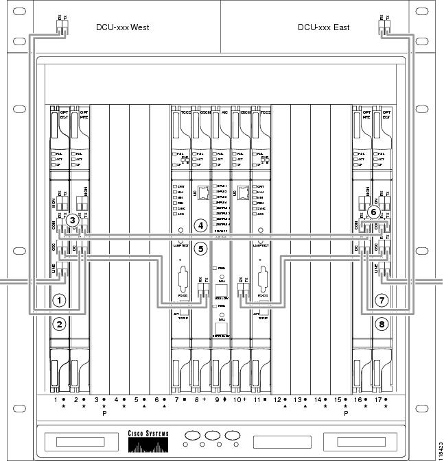
Figure 11-66 shows an example of a line amplifier node with cabling.
Figure 11-66 Fibering a Line Amplifier Node
|
|
Side A DCU TX to Side A OPT-PRE DC RX4 |
|
|
|
|
|
||
|
|
|
||
|
|
|
|
4.If a DCU is not installed, a 4-dB attenuator loop, +/– 1 dB, must be installed between the OPT-PRE DC ports. |
11.7.5 OSC Regeneration Node Fiber-Optic Cabling
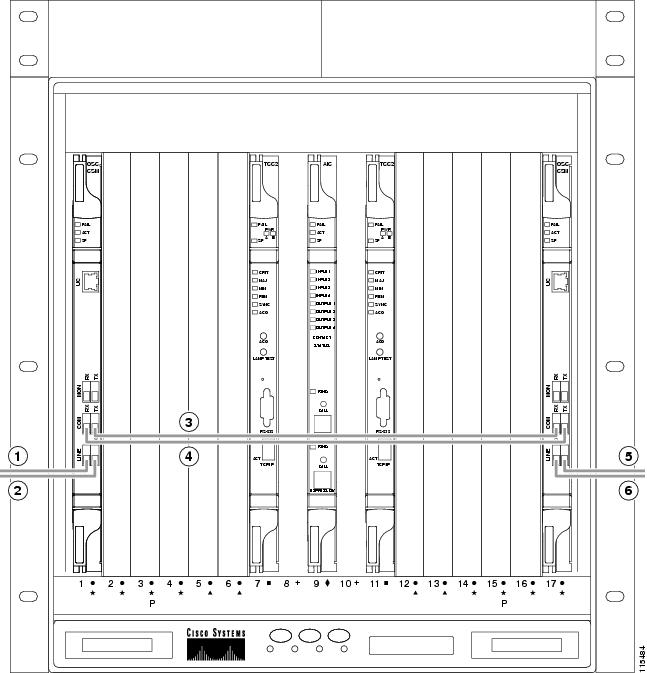
The following rules generally apply to OSC regeneration node cabling:
Figure 11-67 shows an example of an OSC regeneration node with cabling.
Figure 11-67 Fibering an OSC Regeneration Node
11.7.6 Amplified or Passive OADM Node Fiber-Optic Cabling
The two sides of the OADM node do not need to be symmetrical. On each side, Cisco TransportPlanner can create one of the following four configurations:
Note![]() Amplified OADM nodes contain OPT-PRE cards and/or OPT-BST cards. Passive OADM nodes do not. Both contain add/drop channel or band cards.
Amplified OADM nodes contain OPT-PRE cards and/or OPT-BST cards. Passive OADM nodes do not. Both contain add/drop channel or band cards.
The following rules generally apply for OADM node express path cabled connections:
- TX ports should only be connected to RX ports.
- EXP ports are connected only to COM ports in between AD-xC-xx.x or AD-xB-xx.x cards that all belong to Side B (that is, they are daisy-chained).
- EXP ports are connected only to COM ports in between AD-xC-xx.x or AD-xB-xx.x cards that all belong to Side A (that is, they are daisy-chained).
- The EXP port of the last AD-xC-xx.x or AD-xB-xx.x card on Side A is connected to the EXP port of the first AD-xC-xx.x or AD-xB-xx.x card on Side B.
- The OPT-BST COM RX port is connected to the nearest (in slot position) AD-xC-xx.x or AD-xB-xx.x COM TX port.
- The OPT-PRE COM TX port is connected to the nearest (in slot position) AD-xC-xx.x or AD-xB-xx.x COM RX port.
- If OADM cards are located in adjacent slots, the TCC2/TCC2P/TCC3/TNC/TSC card assumes that they are connected in a daisy-chain between the EXP ports and COM ports as noted previously.
- The first Side A AD-xC-xx.x or AD-xB-xx.x card COM RX port is connected to the Side A OPT-PRE or OSC-CSM COM TX port.
- The first Side A AD-xC-xx.x or AD-xB-xx.x card COM TX port is connected to the Side A OPT-BST or OSC-CSM COM RX port.
- The first Side B AD-xC-xx.x or AD-xB-xx.x card COM RX port is connected to the Side B OPT-PRE or OSC-CSM COM TX port.
- The first Side B AD-xC-xx.x or AD-xB-xx.x card COM TX port is connected to the Side B OPT-BST or OSC-CSM RX port.
- If a Side A OPT-PRE is present, the Side A OPT-BST or OSC-CSM COM TX port is connected to the Side A OPT-PRE COM RX port.
- If a Side B OPT-PRE is present, the Side B OPT-BST or OSC-CSM COM TX port is connected to the Side B OPT-PRE COM RX port.
The following rules generally apply for OADM node add/drop path cabled connections:
–![]() 4MD-xx.x COM TX or 4MD-xx.x COM RX ports
4MD-xx.x COM TX or 4MD-xx.x COM RX ports
–![]() Another AD-xB-xx.x add/drop port (a pass-through configuration)
Another AD-xB-xx.x add/drop port (a pass-through configuration)
- An AD-xB-xx.x add/drop band port is only connected to a 4MD-xx.x card belonging to the same band.
- For each specific AD-xB-xx.x card, the add and drop ports for that band card are connected to the COM TX and COM RX ports of the same 4MD-xx.x card.
- The AD-xB-xx.x and 4MD-xx.x cards are located in the same side (the connected ports all have the same line direction).
The following rules generally apply for OADM node pass-through path cabled connections:
- Pass-through connections are only established between add and drop ports on the same band or channel and in the same line direction.
- AD-xC-xx.x or AD-xB-xx.x add/drop ports must be connected to other AD-xC-xx.x or AD-xB-xx.x add/drop ports (as pass-through configurations).
- Add (RX) ports must be connected to drop (TX) ports.
- 4MD-xx.x client input/output ports must be connected to other 4MD-xx.x client input/output ports.
- A Side A AD-xB-xx.x drop (TX) port is connected to the corresponding Side A 4MD-xx.x COM RX port.
- A Side A AD-xB-xx.x add (RX) port is connected to the corresponding Side A 4MD-xx.x COM TX port.
- An Side B AD-xB-xx.x drop (TX) port is connected to the corresponding Side B 4MD-xx.x COM RX port.
- An Side B AD-xB-xx.x add (RX) port is connected to the corresponding Side B 4MD-xx.x COM TX port.
Figure 11-68 shows an example of an amplified OADM node with AD-1C-xx.x cards installed.
Note![]() Figure 11-68 is an example. Always install fiber-optic cables based on the Cisco TransportPlanner Internal Connections table for your site.
Figure 11-68 is an example. Always install fiber-optic cables based on the Cisco TransportPlanner Internal Connections table for your site.
Figure 11-68 Fibering an Amplified OADM Node
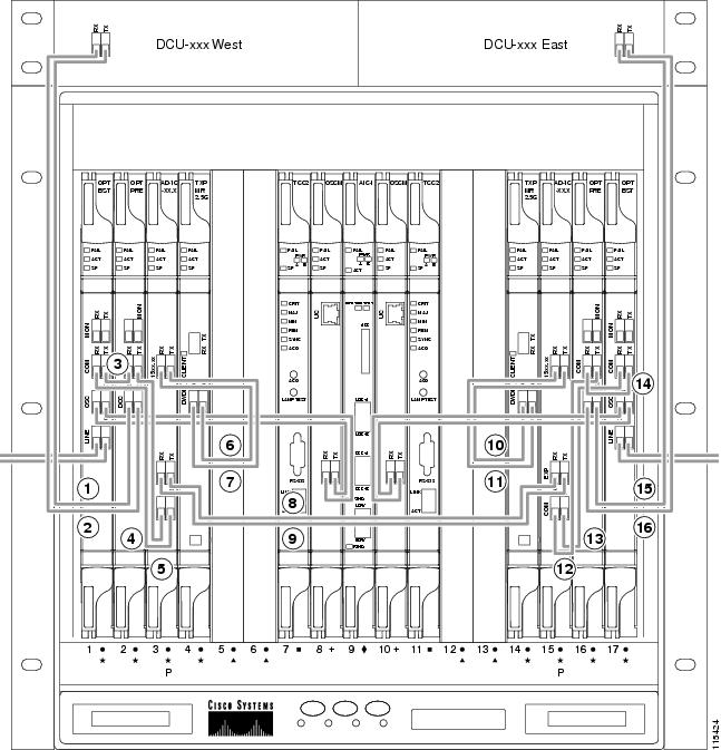
|
|
Side A DCU TX to Side A OPT-PRE DC RX5 |
|
|
|
|
|
Side B TXP_MR_2.5G DWDM RX to Side B AD-1C-xx.x (15xx.xx) TX |
|
|
|
|
Side B TXP_MR_2.5G DWDM TX to Side B AD-1C-xx.x (15xx.xx) RX |
|
|
|
|
||
|
|
|
||
|
|
Side A AD-1C-xx.x (15xx.xx) RX to Side A TXP_MR_2.5G DWDM TX |
|
|
|
|
Side A AD-1C-xx.x (15xx.xx) TX to Side A TXP_MR_2.5G DWDM RX |
|
|
|
|
|
|
5.If a DCU is not installed, a 4-dB attenuator loop, +/ 1 dB, must be installed between the OPT-PRE DC ports. |
Figure 11-69 shows an example of a passive OADM node with two AD-1C-xx.x cards installed.
Figure 11-69 Fibering a Passive OADM Node
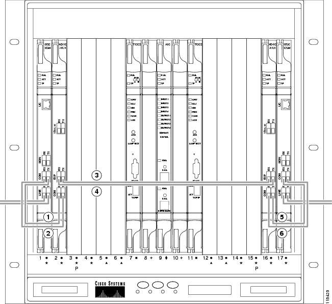
|
|
|
||
|
|
|
||
|
|
|
11.7.7 ROADM Node Fiber-Optic Cabling
The following rules generally apply to ROADM node cabling:
- The Side A OPT-BST or OSC-CSM COM TX port is connected to the Side A OPT-PRE COM RX port.
- The Side A OPT-PRE COM TX port is connected to the Side A 32WSS COM RX port.
- The Side A OPT-BST or OSC-CSM COM RX port is connected to the Side A 32WSS COM TX port.
- The Side A OPT-BST (if installed) OSC TX port is connected to the Side A OSCM RX port.
- The Side A OPT-BST (if installed) OSC RX port is connected to the Side A OSCM TX port.
- The Side A 32WSS EXP TX port is connected to the Side B 32WSS EXP RX port.
- The Side A 32WSS EXP RX port is connected to the Side B 32WSS EXP TX port.
- The Side A 32WSS DROP TX port is connected to the Side A 32DMX COM RX port.
- The Side A 40-WSS-C/40-WSS-CE DROP TX port is connected to the Side A 40-DMX-C or 40-DMX-CE COM RX port.
- The Side B OPT-BST or OSC-CSM COM TX port is connected to the Side B OPT-PRE COM RX port.
- The Side B OPT-PRE COM TX port is connected to the Side B 32WSS COM RX port.
- The Side B OPT-BST or OSC-CSM COM RX port is connected to the Side B 32WSS COM TX port.
- The Side B OPT-BST (if installed) OSC TX port is connected to the Side B OSCM RX port.
- The Side B OPT-BST (if installed) OSC RX port is connected to the Side B OSCM TX port.
- The Side B 32WSS DROP TX port is connected to the Side B 32DMX COM RX port.
- The Side B 40-WSS-C/40-WSS-CE DROP TX port is connected to the Side B 40-DMX-C or 40-DMX-CE COM RX port.
Figure 11-70 shows an example of an amplified ROADM node with cabling.
Note![]() Figure 11-70 is an example. Always install fiber-optic cables based on the Cisco TransportPlanner Internal Connections table for your site.
Figure 11-70 is an example. Always install fiber-optic cables based on the Cisco TransportPlanner Internal Connections table for your site.
Figure 11-70 Fibering a ROADM Node
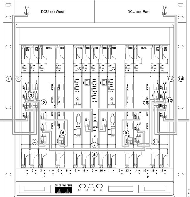
|
|
Side A DCU TX to Side A OPT-PRE DC RX6 |
|
|
|
|
|
||
|
|
|
||
|
|
|
||
|
|
|
||
|
|
|
||
|
|
|
|
6.If a DCU is not installed, a 4-dB attenuator loop, +/–1 dB must be installed between the OPT-PRE DC ports. |
11.8 Automatic Node Setup
Automatic node setup (ANS) is a TCC2/TCC2P/TCC3/TNC/TSC function that adjusts values of the variable optical attenuators (VOAs) on the DWDM channel paths to equalize the per channel power at the amplifier input. This power equalization means that at launch, all channels have the same amplifier power, independent of the input signal on the client interface and independent of the path crossed by the signal inside the node. This equalization is needed for two reasons:
- Every path introduces a different penalty on the signal that crosses it.
- Client interfaces add their signal to the ONS 15454 DWDM ring with different power levels.
To support ANS, integrated VOAs and photodiodes are provided in the following cards:
- AD-xB-xx.x card express and drop paths
- AD-xC-xx.x card express and add paths
- 4MD-xx.x card add paths
- 32MUX-O card add paths
- 32WSS/40-WSS-C/40-WSS-CE/40-WXC-C/80-WXC-C add, drop, and pass through paths
- 32DMX-O card drop paths
- 32DMX, 40-DMX-C, 40-DMX-CE card input port
- 40-MUX-C card output port
- 40-SMR1-C/40-SMR2-C add, drop, and pass through ports
- PSM card input and output ports (both working and protect path)
Optical power is equalized by regulating the VOAs. Based on the expected per channel power, ANS automatically calculates the VOA values by:
- Reconstructing the different channel paths.
- Retrieving the path insertion loss (stored in each DWDM transmission element).
VOAs operate in one of three working modes:
- Automatic VOA Shutdown—In this mode, the VOA is set at maximum attenuation value. Automatic VOA shutdown mode is set when the channel is not provisioned to ensure system reliability in the event that power is accidentally inserted.
- Constant Attenuation Value—In this mode, the VOA is regulated to a constant attenuation independent from the value of the input signal. Constant attenuation value mode is set on VOAs associated to aggregated paths.
- Constant Power Value—In this mode, the VOA values are automatically regulated to keep a constant output power when changes occur to the input power signal. This working condition is set on VOAs associated to a single channel path.
ANS calculates the following VOA provisioning parameters:
Optical patchcords are passive devices that are modeled by the two termination points, each with an assigned slot and port. If user-provisioned optical patchcords exist, ANS checks if the new connection is feasible according to internal connection rules. If the user connection violates one of the rules, ANS returns a denied message. ANS requires the expected wavelength to be provisioned. When provisioning the expected wavelength, the following rules apply:
- The card family generically characterizes the card name, and not the particular wavelengths supported (for example, AD-2C-xx.x for all two-channel OADMs).
- At the provisioning layer, you can provision a generic card for a specific slot using CTC or TL1.
- Wavelength assignment is done at the port level.
- An equipment mismatch alarm is raised when a mismatch between the identified and provisioned value occurs. The default value for the provisioned attribute is AUTO.
ONS 15454 ANS parameters set the values required for the node to operate successfully. Cisco TransportPlanner calculates the ANS parameters based on the requirements for a planned network. Cisco TransportPlanner exports the parameters to an ASCII, NE update file. When the NE update file is imported in CTC, the Provisioning > WDM-ANS > Provisioning tab is populated with the ANS parameters to provision the node for the network. These ANS parameters can be modified. All the ANS parameters are mapped to the physical ports of the cards. ANS parameters can also be manually added or deleted in the Provisioning tab. The ranges for the values of the ANS parameters is shown in Table 11-11. For more information on how to add an ANS parameter, refer to the “Turn Up a Node” chapter in the Cisco ONS 15454 DWDM Procedure Guide.
Note![]() The Provisioning > WDM-ANS > Provisioning tab in CTC is empty if the NE update file is not imported.
The Provisioning > WDM-ANS > Provisioning tab in CTC is empty if the NE update file is not imported.
Note![]() It is recommended that you use the Cisco TransportPlanner NE Update file to provision the ANS parameters instead of manually adding all the parameters in CTC. ANS provisioning parameters must be manually changed by Cisco qualified personnel only. Setting incorrect ANS provisioning (either as preamplifier or booster input power thresholds) may impact traffic.
It is recommended that you use the Cisco TransportPlanner NE Update file to provision the ANS parameters instead of manually adding all the parameters in CTC. ANS provisioning parameters must be manually changed by Cisco qualified personnel only. Setting incorrect ANS provisioning (either as preamplifier or booster input power thresholds) may impact traffic.
|
|
|
|---|---|
ANS parameters can be viewed in the node view Provisioning > WDM-ANS > Provisioning tab, as shown in Figure 11-71.
Figure 11-71 WDM-ANS Provisioning
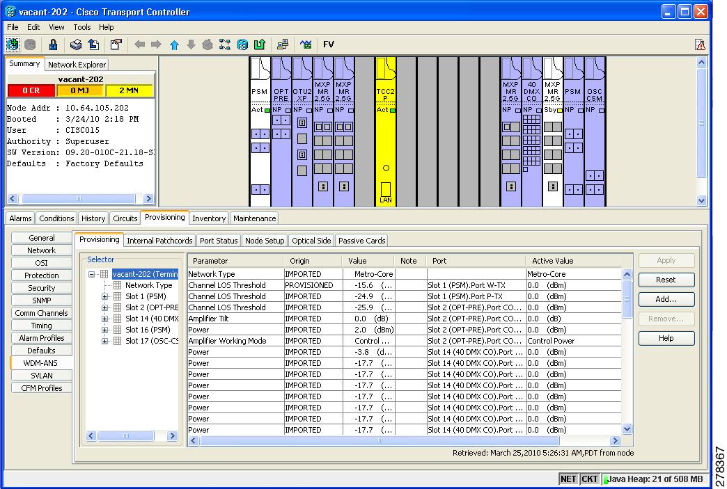
The Provisioning > WDM-ANS > Provisioning tab presents the following information:
- Selector—Presents the ANS parameters in a tree view based on physical position. Clicking the + or – expands or collapses individual tree elements. Clicking a tree element displays the element parameters in the table on the right. For example, clicking the node name at the top displays all the node ANS parameters or clicking Slot 1 (PSM) displays the PSM amplifier parameters only. The ANS parameters can be sorted according to physical position.
- Parameter—Displays the ANS parameter name.
- Origin—Indicates how the parameter was calculated:
–![]() Imported—The value was set by importing the CTP XML file.
Imported—The value was set by importing the CTP XML file.
–![]() Provisioned—The value was manually provisioned.
Provisioned—The value was manually provisioned.
–![]() Automatic—The value is automatically calculated by the system using the Raman provisioning wizard. For more information on how to provision using a wizard, see the “DLP-G468 Configure the Raman Pump Using an Installation Wizard” task in the Cisco ONS 15454 DWDM Procedure Guide.
Automatic—The value is automatically calculated by the system using the Raman provisioning wizard. For more information on how to provision using a wizard, see the “DLP-G468 Configure the Raman Pump Using an Installation Wizard” task in the Cisco ONS 15454 DWDM Procedure Guide.
- Value—Displays the ANS parameter value. The values can be modified manually, although manually modifying the ANS parameters is not recommended.
- Note—Displays information for parameters that could not be calculated, that is, parameters with Unknown appearing in the Value column.
- Port —Displays the port value. Port is represented as Slot.Port.
- Active Value —Displays the active parameter value. The active value cannot be modified manually. When you modify the parameter value in the Value field, the active value is updated with the modified value after you run ANS.
The Provisioning > WDM-ANS > Port Status tab presents the following information:
- Port—Displays the port value. The port is represented as Slot.Port.
- Parameter—Displays the ANS parameter name.
- Result—After you run ANS, one of the following statuses is provided for each ANS parameter in the Result column:
–![]() Success - Changed—The parameter setpoint was recalculated successfully.
Success - Changed—The parameter setpoint was recalculated successfully.
–![]() Success - Unchanged—The parameter setpoint did not need recalculation.
Success - Unchanged—The parameter setpoint did not need recalculation.
–![]() Unchanged - Port in IS state—ANS could not modify the setpoint because the port is in IS state.
Unchanged - Port in IS state—ANS could not modify the setpoint because the port is in IS state.
–![]() Fail - Out of Range—The calculated setpoint is outside the expected range.
Fail - Out of Range—The calculated setpoint is outside the expected range.
–![]() Fail - Missing Input Parameter—The parameter could not be calculated because the required provisioning data is unknown or unavailable.
Fail - Missing Input Parameter—The parameter could not be calculated because the required provisioning data is unknown or unavailable.
–![]() Not Applicable State—Ports are not in use.
Not Applicable State—Ports are not in use.
- Value—Displays the parameter value.
- Set By—Displays the application that sets this parameter. This field can take the following values:
A parameter could be set by more than one application. For example, VOA Attenuation parameter could be set by both ANS and APC. In this case, individual entries will be displayed for ANS and APC.
11.8.1 Raman Setup and Tuning
Raman amplification occurs in the optical fiber and the consequent Raman gain depends on the characteristics of the span (attenuator presence, fiber type, junctions, etc.). As two Raman pumps at two different wavelengths are used to stimulate the Raman effect, not only is the total signal power calculation significant, but the right mix of power to ensure gain flatness is crucial. These setpoints of the total Raman power and Raman ratio can be configured on the OPT-RAMP-C or OPT-RAMP-CE card in three ways:
For information on how to configure the setpoints on the OPT-RAMP-C or OPT-RAMP-CE card, see the Cisco ONS 15454 DWDM Procedure Guide.
Raman amplification on OPT-RAMP-C or OPT-RAMP-CE cards depends on the optical fiber installed. Therefore, Raman total power and Raman ratio values calculated using the Raman installation wizard via CTC is more accurate than the values provisioned by loading the CTP XML file. For this reason, the value provisioned using the wizard cannot be overridden by the CTP XML file. However, the values provisioned using the wizard or the CTP XML file can be overriden by manually provisioning the parameters.
When the Raman installation is completed, a report of the status of Raman configuration on a node in the OPT-RAMP-C or OPT-RAMP-CE card can be viewed in the Maintenance > Installation tab when you are in card view.
The Installation tab displays the following fields:
- User—Name of user who configured the Raman pump.
- Date—Date when the Raman pump was configured.
- Status
–![]() Raman Not Tuned—The OPT-RAMP-C or OPT-RAMP-CE card was provisioned but ANS was not launched.
Raman Not Tuned—The OPT-RAMP-C or OPT-RAMP-CE card was provisioned but ANS was not launched.
–![]() Tuned by ANS—ANS was run successfully and the basic ANS parameters were applied.
Tuned by ANS—ANS was run successfully and the basic ANS parameters were applied.
–![]() Tuned by Wizard—The Raman installation wizard was run successfully without errors.
Tuned by Wizard—The Raman installation wizard was run successfully without errors.
–![]() Tuned by User Acceptance—The Raman installation wizard was completed with errors and the user accepted the values that the wizard calculated.
Tuned by User Acceptance—The Raman installation wizard was completed with errors and the user accepted the values that the wizard calculated.
–![]() Raman is Tuning—The Raman installation wizard is running.
Raman is Tuning—The Raman installation wizard is running.
- S1Low (dBm)—See Table 11-12 .
- S1High (dBm)—See Table 11-12 .
- S2Low (dBm)—See Table 11-12 .
- S2High (dBm)—See Table 11-12 .
- Power (mW)—Total Raman power setpoints.
- Ratio—Raman pump ratio setpoint.
- Gain—Expected Raman gain that the wizard calculated.
- Actual Tilt—Expected Raman tilt that the wizard calculated.
- Fiber Cut Recovery—Status of the fiber cut restoration.
–![]() Executed—The restore procedure was completed successfully.
Executed—The restore procedure was completed successfully.
–![]() Pending—The restore procedure is not complete.
Pending—The restore procedure is not complete.
–![]() Failed—The system failed to execute the procedure.
Failed—The system failed to execute the procedure.
The Raman pump is equipped with two different Raman pumps transmitting powers (P1 and P2) at two different wavelengths  1 and
1 and  2. During installation, the two pumps alternatively turn ON and OFF at two different power values.
  1 and
1 and  2 signals are used as probes at the end of spans to measure Raman gain efficiency of the two Raman pumps separately.
The example in Raman Gain on Node B shows the Raman gain on an OPT-RAMP-C or OPT-RAMP-CE card in Node B that was measured by setting the wavelength and power measurements as follows:
 1=1530.33 nm signal probe at Node A
 2=1560.61 nm signal probe at Node A
Figure 11-72 Raman Gain on Node B
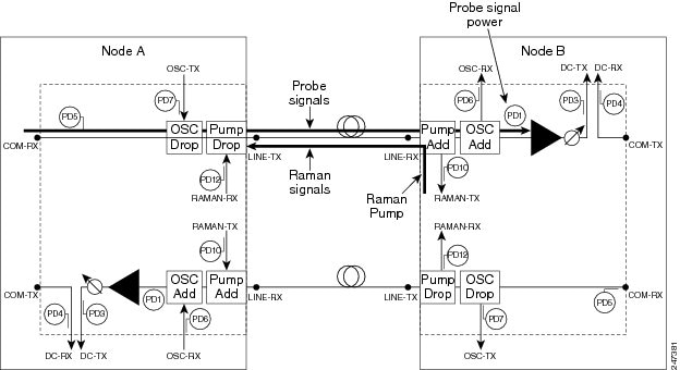
The S1low, S1high, S2low, and S2low values in the Maintenance > Installation tab are based on the power values read on the LINE-RX port of Node B.
|
|
|
|
|
|---|---|---|---|
 1=1530.33 nm at Node A 1=1530.33 nm at Node A
|
|||
 2=1560.61 nm at Node A 2=1560.61 nm at Node A
|
|||
11.9 DWDM Functional View
DWDM functional view offers a graphical view of the DWDM cards and the internal connections between them in an MSTP node. The functional view also shows cards and connections for multidegree MSTP nodes (up to eight sides). To navigate to the functional view of a DWDM node, use the following navigational path in CTC when you are in node view:
Provisioning > WDM-ANS > Internal Patchcords > Functional View
An example of the functional view for an eight-sided node is shown in Figure 11-73.
Figure 11-73 Functional View for an Eight-Sided Node
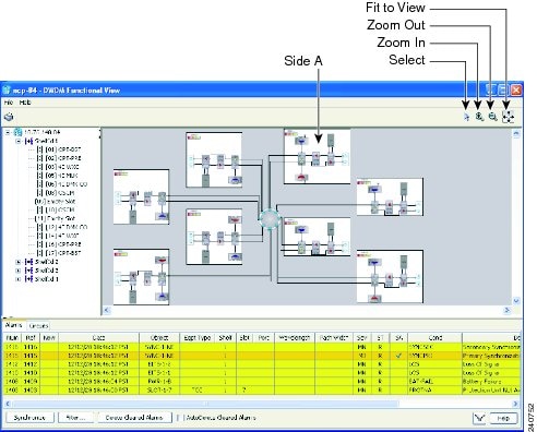
11.9.1 Navigating Functional View
The functional view has two main panes. The upper pane contains a tree view of the shelves and a graphical view of the shelf equipment. The lower pane describes alarms and circuits in a tabular format.
The upper pane in Figure 11-73 is divided into a left pane and a right pane. The left pane shows a tree structure view of the shelf or shelves in the MSTP system. You can expand the tree view of a shelf to show the slot usage in that shelf. The right pane is a graphical view of the sides in the shelf. In the case of Figure 11-73, there are eight sides (A through H). Side A is located as shown in the figure. All of the cards in each side are grouped together.
The meanings of the icons in the upper right corner are as follows:
- Select—use this icon to select a graphical element in the graphical view pane.
- Patchcord—Use this icon to create an internal patchcord between cards.
Note![]() The Patchcord icon is not functional for Software Release 8.5.
The Patchcord icon is not functional for Software Release 8.5.
- Zoom In/Zoom Out—Use these icons to zoom in or zoom out in the graphical display pane.
- Fit to View—Use this icon to have the graphical view fit the space available on your screen.
The bottom pane can be used to display alarms (using the Alarms tab) or Circuits (using the Circuits tab). Clicking the Alarms tab displays the same information as the Alarms tab in the network, node, or card view. Clicking the Circuits tab displays the same information as the Alarms tab in the network, node, or card view.
11.9.2 Using the Graphical Display
This section explains how to use the graphical portion of the display to gather information about the cards and ports.
11.9.2.1 Displaying a Side
Double-click a side to show the details of that side. For example, if you double-click Side A in Figure 11-73, the result is as shown in Figure 11-74.
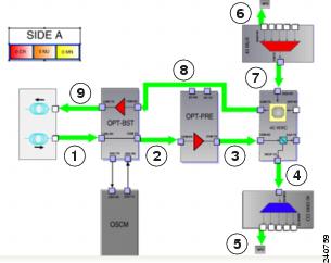
The green arrows in the diagram represent the DWDM optical path within the selected side. The optical path in this instance is summarized as follows:
1.![]() The light enters the OPT-BST card LINE-RX port from the optical span.
The light enters the OPT-BST card LINE-RX port from the optical span.
2.![]() The path continues out of the OPT-BST card COM-TX port to the COM-RX port of the OPT-PRE card.
The path continues out of the OPT-BST card COM-TX port to the COM-RX port of the OPT-PRE card.
3.![]() The OPT-PRE card sends the optical signal out of its COM-TX port to the 40-WXC COM-RX input port.
The OPT-PRE card sends the optical signal out of its COM-TX port to the 40-WXC COM-RX input port.
4.![]() The 40-WXC card sends the signal to be locally dropped out of its DROP-TX port to the 40-DMX/40-DMX-CE card COM-RX port.
The 40-WXC card sends the signal to be locally dropped out of its DROP-TX port to the 40-DMX/40-DMX-CE card COM-RX port.
5.![]() The 40-DMX/40-DMX-CE card sends the dropped signal out on one of its multifiber push on (MPO) connectors to the block labeled MPO. When you expand the MPO block (double-click it or right-click it and select Down), you will see a muxponder (MUX) card inside the MPO block. One of the eight optical fibers in the MPO cable is connected to the MUX trunk port.
The 40-DMX/40-DMX-CE card sends the dropped signal out on one of its multifiber push on (MPO) connectors to the block labeled MPO. When you expand the MPO block (double-click it or right-click it and select Down), you will see a muxponder (MUX) card inside the MPO block. One of the eight optical fibers in the MPO cable is connected to the MUX trunk port.
6.![]() The optical signal from the trunk port of the MXP card inside the MPO block enters the 40-MUX card at one of its five MPO connectors.
The optical signal from the trunk port of the MXP card inside the MPO block enters the 40-MUX card at one of its five MPO connectors.
7.![]() The 40-MUX card sends the optical signal out of its COM-TX port to the ADD-RX port of the 40-WXC card.
The 40-MUX card sends the optical signal out of its COM-TX port to the ADD-RX port of the 40-WXC card.
8.![]() The added signal from the MXP gets sent out on the COM-TX port of the 40-WXC card to the COM-RX port of the OPT-BST card.
The added signal from the MXP gets sent out on the COM-TX port of the 40-WXC card to the COM-RX port of the OPT-BST card.
9.![]() Finally, the OPT-BST card sends the optical signal out onto the span from its LINE-TX port.
Finally, the OPT-BST card sends the optical signal out onto the span from its LINE-TX port.
11.9.2.2 Displaying Card Information
In the functional view graphical pane, you can double-click a card to bring up the usual CTC card view.
You can also move the mouse over a card to display information about the card. For example, when the mouse is placed over the OPT-BST card in Side A, the tooltip text displays sh1/s1 (OPT-BST), indicating that the OPT-BST card for Side A is located in Shelf 1, Slot 1. See Figure 11-75.
Figure 11-75 Side A OPT-BST Card Shelf and Slot Information
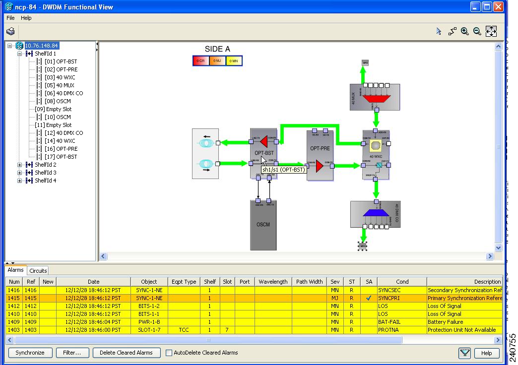
11.9.2.3 Displaying Port Information
Move the mouse over a port on a card to display information about the port. For example, when the mouse is placed over the top left port of the 40-MUX card in Side A, the tooltip text displays CARD_PORT-BAND-1-RX, indicating that the 40-MUX port being pointed to is for the first band of wavelengths (wavelengths 1 to 8) to be added into the optical path at the 40-MUX card. These wavelengths come into the 40-MUX card from a transponder (TXP) or muxponder (MXP) on an MPO connector, which contains eight integrated optical fibers. See Figure 11-76.
Figure 11-76 Side A 40-MUX Port Information
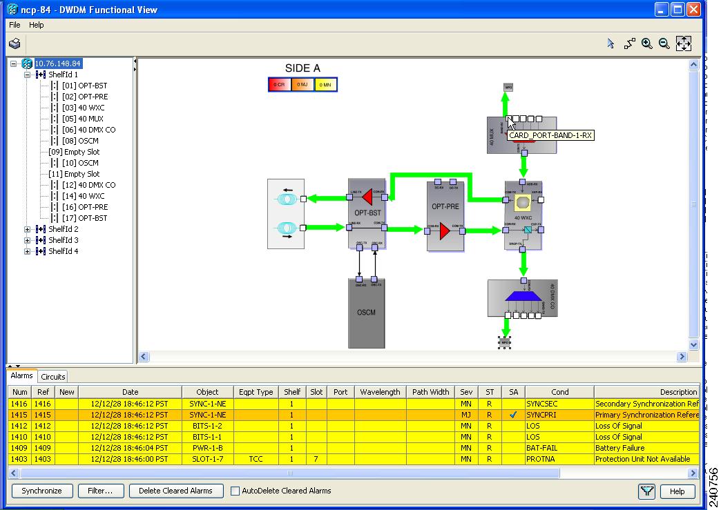
11.9.2.4 Displaying Patchcord Information
Move the mouse over a patchcord to see the state of the output and input port associated with that patchcord. See Figure 11-77.
Figure 11-77 Patchcord Input and Output Port State Information
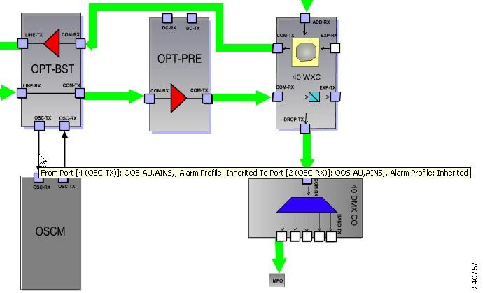
11.9.2.5 Displaying MPO Information
To show the details inside an MPO block, double-click it or right-click it and select Down. When the detailed view is visible, right-click inside the MPO block and select Upper View to collapse the block. When you move the mouse over the MPO block, the associated wavelengths are displayed as a tool tip (see Figure 11-78).
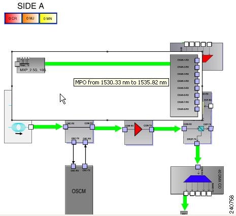
11.9.2.6 Alarm Box Information
Within the side display, an alarm box is shown that gives the alarm count for the Critical, Major, and Minor alarms that affect that side. This alarm summary is only for the side, and is different from the alarms under the Alarms tab, where all of the alarms for the system are summarized. If an alarm under the Alarms tab appears that has to do with Side A, for example, only the appropriate alarm count in the Alarm box for Side A is incremented. The alarm counts in the Alarm boxes for the other nodes (B through H) are not incremented. In the graphical view of a side, the card icon or port icon changes color to reflect the severity of an alarm associated with the card (red, orange, or yellow). The color of the MPO block reflects the color of highest alarm severity for the elements in the MPO block.
11.9.2.7 Transponder and Muxponder Information
All of the TXP and MXP cards connected with patchcords are grouped together under the MPO icon. In the node shown in Figure 11-73, there is an MXP card in Side A that is connected to the 40-MUX card and to the 40-DMX/40-DMX-CE card. The MXP card is connected through the 40-MUX card to the add port on the 40-WXC card and it is also connected through the 40-DMX/40-DMX-CE card to the drop port on the 40-WXC card. To view the connections to the MXP card from the 40-MUX card, double-click the MPO icon. Figure 11-79 shows the MPO icon before double-clicking it and Figure 11-80 shows the result after double-clicking it.
Note![]() In the case of a protected TXP (TXPP) or MXP (MXPP) card, the card icon has a label indicating the active trunk and the protected trunk.
In the case of a protected TXP (TXPP) or MXP (MXPP) card, the card icon has a label indicating the active trunk and the protected trunk.
Figure 11-79 Side A MPO Connection to an MXP Before Double-Clicking
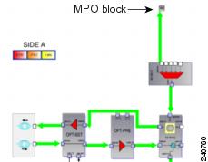
Figure 11-80 Side A MPO Connection to an MXP After Double-Clicking
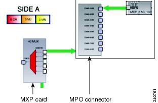
11.9.2.8 Changing the Views
When you right-click inside of a side view, a shortcut menu allows you to do the following (see Figure 11-81):
- Fit to View—Fits the side view into the available display space.
- Delete Side—Deletes the selected side.
- Rotate Left—Rotates the side 90 degrees counterclockwise (all connections are maintained).
- Rotate Right—Rotates the side 90 degrees clockwise (all connections are maintained).
- Horizontal Flip—Flips the side horizontally (all connections are maintained).
- Vertical Flip—Flips the side vertically (all connections are maintained).
After you have selected Fit to View for a side, you can right-click in the side view to bring up a new menu with the following selections (see Figure 11-82):
- Go to Upper View—Returns to the previous view.
- Perform AutoLayout—Optimizes the placement of the cards and the connections between them.
Figure 11-81 Side A View Options
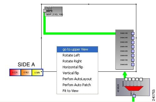
Figure 11-82 Side A View Options (after Selecting Fit to View)
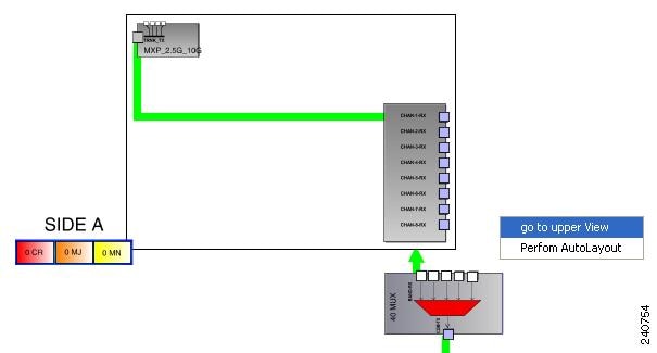
11.9.2.9 Selecting Circuits
When the Circuits tab is selected, the circuits for the functional view are shown. The patchcord lines in the graphical display are normally black in color. A patchcord line becomes green only when you select a circuit associated with the patchcord that carries the selected circuit.
11.9.2.10 Displaying Optical Path Power
To show the optical power present in an optical path, move the mouse over the desired optical path (green line). A tooltip shows the power along the optical path in dBm (see Figure 11-83).
Figure 11-83 Optical Path Power
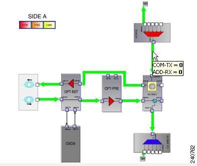
11.10 DWDM Network Functional View
The DWDM Network Functional View (NFV) displays a graphical representation of the circuit connections, optical power, and alarms in the DWDM network. The NFV allows you to view the circuit connections and flow of data at the network level. The NFV also helps to find an alternate network path if there is a loss of signal in the network.
The NFV offers dual options to view the network:
- Graphical view—Displays the circuit connections, optical power, and alarms of a circuit through a graphical representation. To view the graphical display of the circuit connections, select the circuit listed in the upper left pane. Click dB, SL, and PV button on the toolbar to view the optical power of the selected circuit, span loss of the desired span, and insertion loss of the patchchord respectively. For more information refer to Using the Graphical Display.
- Viewing the circuit details in tabular format—The circuit connections, optical power, and alarms of a circuit are displayed in a tabular format (seen in the left pane of the Network Functional View). For more information refer to Selecting the Circuit.
For information on how to view optical power values and alarms of the circuit selected in the Network Functional View, see the “View Optical Power Values and Alarms Using the Network Functional View” task in the Cisco ONS 15454 DWDM Procedure Guide.
11.10.1 Navigating Network Functional View
This section explains how to navigate to the network functional view (NFV). To navigate to the NFV, go to the network view in the CTC and click the FV button on the toolbar. The DWDM Network Functional View window opens.
The NFV is similar to the DWDM functional view in its graphical layout and behavior at the node level. For additional information, see “DWDM Functional View” section.
The network functional view has two main panes (Figure 11-84):
- Left pane —Is divided into an upper pane and a lower pane. The upper pane has three tabs that are listed in Table 11-13 , and the lower pane displays the graphical overview of the network.
- Right pane —Displays the graphical view of all the nodes and devices in the network.
You can hide or close the upper and lower panes, and view only the network map in the NFV. Click the Close button on the title bar to close the pane or click the Toggle auto-hide button on the title bar to hide the pane. Click the Reset To Default button on the toolbar to restore (or view) all the panes.
Figure 11-84 DWDM Network Functional View
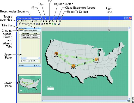
11.10.2 Using the Graphical Display
This section explains how to use the graphical display to gather information on circuits, optical power, and alarms for the nodes.
To expand a node, click on the network functional view graph and Press F2. The node opens in a double zoom mode and you can read the power information in the zoom out view. Click F2 again to zoom-in or return to the normal view. Additionally, to zoom-in and zoom-out the graph on the network functional view, press the Ctrl key and scroll up and down with the scroll wheel on your mouse. Click Reset Nodes Zoom button on the toolbar to reset the graphical view to the default zoom size.
The keystroke commands provide the keyboard shortcuts for graphical control of the NFV. To access the keystroke commands, click Help > Keystroke commands.
Note![]() To open and view the nodes in the network functional view, right-click the node and choose Open Node FV. Or double-click on the Node to open the node FV. To navigate to the node level, right-click FV > Node FV. To close all the opened nodes in the FV, click Close Expanded Nodes button on the toolbar. To zoom-in and zoom-out of the open node, press the Ctrl key and scroll up and down with the scroll wheel on your mouse.
To open and view the nodes in the network functional view, right-click the node and choose Open Node FV. Or double-click on the Node to open the node FV. To navigate to the node level, right-click FV > Node FV. To close all the opened nodes in the FV, click Close Expanded Nodes button on the toolbar. To zoom-in and zoom-out of the open node, press the Ctrl key and scroll up and down with the scroll wheel on your mouse.
When you have multiple node FVs opened, you cannot view the graphical details of the individual node due to overlapping of the map. To avoid overlapping of the map, do the following:
1.![]() Select the entire expanded node (all sides), and move it out of the map (to the desired location). To select the entire node, click on the title bar of the node and Press Ctrl A.
Select the entire expanded node (all sides), and move it out of the map (to the desired location). To select the entire node, click on the title bar of the node and Press Ctrl A.
2.![]() Move the individual sides of the node one-by-one back to the proper position inside the network map. To move the individual sides of the node, select the side and move it to the desired location.
Move the individual sides of the node one-by-one back to the proper position inside the network map. To move the individual sides of the node, select the side and move it to the desired location.
11.10.2.1 Displaying Optical Power
The NFV toolbar has the following buttons that displays the optical power information of the circuits:
- dB (Power)—Click the dB button on the toolbar to view the optical power information of the circuits. The optical power in the optical path in dBm is displayed in the power balloon.
You can view the aggregated power only for those nodes that have the FV open. To open the node FV, right-click the node and choose Open Node FV. It also shows the per channel estimated power of the ports of the selected circuit.
Right-click the internal patchcord link and select Flip Power Balloons to view the power balloon of the selected patchcord. The power balloon is flipped and you can see the power details of the selected patchcord without overlapping.
- SL (Span Loss)—Click the SL button to see the loss of signal of the desired span.
- PV (Patchcord Verification)—Click the PV button to display the insertion loss of the patchcord. The PV calculates the input and output power of the patchcord. You can view the insertion loss of the patchchord only for those nodes that have the FV open. To open the node FV, right-click the node and choose Open Node FV. The insertion loss should not exceed 2dBm. The patchcord lines are colored to indicate the insertion loss:
–![]() Red—Indicates that the insertion loss of the patchcords exceeded 2dBm.
Red—Indicates that the insertion loss of the patchcords exceeded 2dBm.
–![]() White—Indicates that the system was not able to calculate the insertion loss of the patchcord.
White—Indicates that the system was not able to calculate the insertion loss of the patchcord.
–![]() Black—Indicates that the insertion loss of the patchcords is within the limit and not more than 2dBm.
Black—Indicates that the insertion loss of the patchcords is within the limit and not more than 2dBm.
Note![]() Click Refresh on the toolbar, to refresh the optical power and span loss information. The optical power and span loss information is calculated and is refreshed in the graphical display and optical power table.
Click Refresh on the toolbar, to refresh the optical power and span loss information. The optical power and span loss information is calculated and is refreshed in the graphical display and optical power table.
11.10.2.2 Selecting the Circuit
The Circuit tab in the NFV allows you to view the available circuits in the network. Click the Circuit tab to view the list of circuits in the selected network. Choose the circuit from the list to view the circuit level information. A graphical display of the selected circuit and the impacted span is visible in the map. Additionally, you can view the general information (type, source, and destination), status (IS,OOS [ANSI] or unlocked, locked [ETSI]), and physical connection details (wavelength, direction, and span) of the selected circuit.
The circuit can be in any of the following states:
When you switch the selection between the circuits, and if both the circuits are in DISCOVERED_TL1 state, the circuit details of the new selection is not displayed (it may still show the previously selected circuit details).
If you find that the current selection is not refreshed, do either of the following:
- Update all the selected circuits using the Reconfigure Circuit option. Go to CTC Tools > Circuits > Reconfigure Circuits menu to reconfigure the selected circuits. During reconfiguration, CTC reassembles all connections of the selected circuits and VCAT members into circuits based on path size, direction, and alignment.
Note![]() If the information does not refresh when you switch the selection between the circuits in OCH_CC and its OCH_TRAIL (and vice-versa), follow the suggestion provided on how to view the current selection if the screen is not refreshed.
If the information does not refresh when you switch the selection between the circuits in OCH_CC and its OCH_TRAIL (and vice-versa), follow the suggestion provided on how to view the current selection if the screen is not refreshed.
To view the optical power and alarm details of a circuit, click Circuit and select the circuit name from the list to view the following details:
- Optical Power —To view the optical power of the selected circuit, click the Optical Power tab. You can view the optical link status and the span loss of the selected circuit.
- Alarms —To view the alarms of the selected circuit, click the Alarms tab. If a card has one or more alarms (that is part of the selected circuit), the node turns either yellow or red, depending on the severity of the alarm. The alarm in red indicates a major alarm and yellow indicates a minor alarm. If there is an alarm present in the card that is not part of the selected circuit, then the node appears gray.
If a node has alarms that is not part of the selected circuits, then the alarms are not listed in the table, but the node is colored in the graphical view (right pane).
Note![]() At the circuit level, you can view both the node and network level information.
At the circuit level, you can view both the node and network level information.
11.10.2.3 Exporting Reports
You can also export the NFV reports of circuit level information in HTML or JPEG format. The export operation creates two files, an HTML and a JPEG format of the NFV information. The.jpg file provides a graphical representation of the site layout. For more information on exporting the reports, see the “Export Network Functional View Reports” task in the Cisco ONS 15454 DWDM Procedure Guide.
11.11 Non-DWDM (TDM) Networks
Non-DWDM (TDM) Networks take synchronous and asynchronous signals and multiplexes them to a single higher bit rate for transmission at a single wavelength over fiber. When the node is configured as a Non-DWDM Network, the supported MSTP cards — amplifiers, transponders, and muxponders, are used in the standalone mode. MSTP applications like Circuit Provisioning, NLAC and APC are not supported in amplified TDM networks. For more information on how to configure a node as a Non-DWDM network, see the “NTP-G320 Configure the Node as a Non-DWDM Network” section in “Turn Up a Node” chapter in the Cisco ONS 15454 DWDM Procedure Guide.
When the node is configured as a Not-DWDM network, all the amplifiers are configured by default with the following values:
Booster(LINE) amplifiers enable optical safety when used in Non-DWDM. ALS configuration is set to “Auto Restart” by default. A manual restart request is therefore needed to turn up the bidirectional link, in addition with an appropriated cabling (bi-directional) of LINE TX/RX ports.
In NOT-DWDM mode, you must configure significant optical parameters and thresholds before launching the ANS application. For information on how to configure the amplifier, see the “DLP-G693 Configure the Amplifier” section in “Turn Up a Node” chapter in the Cisco ONS 15454 DWDM Procedure Guide. For information on how to configure the PSM behavior, see the “DLP-G694 Configure the PSM” section in “Turn Up a Node” chapter in the Cisco ONS 15454 DWDM Procedure Guide.
When the ANS application is launched, amplifier ports move into IS state and Gain Setpoint is automatically calculated by the card, after initial APR cycle. Gain Setpoint must be equal to MAX [Min Gain Setpoint of the card ; (Power Ref-Pinput)]; where Pinput is the optical power value at the ingress port (COM-RX) of the amplification stage.
 Feedback