- About this Guide
- Cisco ONS Documentation Roadmap for Release 9.2.1
- Chapter 1, Install the Bay and Backplane Connections
- Chapter 2, Install Cards and Fiber-Optic Cable
- Chapter 3, Connect the PC and Log into the GUI
- Chapter 4, Turn Up a Node
- Chapter 5, Turn Up a Network
- Chapter 6, Create Circuits
- Chapter 7, Manage Circuits
- Chapter 8, Monitor Performance
- Chapter 9, Manage Alarms
- Chapter 10, Change Card Settings
- Chapter 11, Change Node Settings
- Chapter 12, Convert Network Configurations
- Chapter 13, Add and Remove Nodes
- Chapter 14, Maintain the Node
- Chapter 15, Power Down the Node
- Chapter 16, DLPs F100 to F199
- Chapter 17, DLPs F200 to F299
- Chapter 18, DLPs F300 to F399
- Chapter 19, DLPs F400 to F499
- Appendix A, CTC Information and Shortcuts
Cisco ONS 15600 SDH Procedure Guide, Releases 9.1 and 9.2.1
Bias-Free Language
The documentation set for this product strives to use bias-free language. For the purposes of this documentation set, bias-free is defined as language that does not imply discrimination based on age, disability, gender, racial identity, ethnic identity, sexual orientation, socioeconomic status, and intersectionality. Exceptions may be present in the documentation due to language that is hardcoded in the user interfaces of the product software, language used based on RFP documentation, or language that is used by a referenced third-party product. Learn more about how Cisco is using Inclusive Language.
- Updated:
- May 26, 2010
Chapter: Chapter 19, DLPs F400 to F499
- DLP-F401 Connect to ONS Nodes Using the CTC Launcher
- DLP-F402 Create a TL1 Tunnel Using the CTC Launcher
- DLP-F403 Create a TL1 Tunnel Using CTC
- DLP-F404 View TL1 Tunnel Information
- DLP-F405 Edit a TL1 Tunnel Using CTC
- DLP-F406 Delete a TL1 Tunnel Using CTC
- DLP-F407 Create an SNMPv3 User
- DLP-F408 Create MIB Views
- DLP-F409 Create Group Access
- DLP-F410 Configure SNMPv3 Trap Destination
- DLP-F411 Delete SNMPv3 Trap Destination
- DLP-F412 Create Notification Filters
- DLP-F413 Manually Configure the SNMPv3 Proxy Forwarder Table
- DLP-F414 Automatically Configure the SNMPv3 Proxy Forwarder Table
- DLP-F415 Manually Configure the SNMPv3 Proxy Trap Forwarder Table
- DLP-F416 Automatically Configure the SNMPv3 Proxy Trap Forwarder Table
- DLP-F417 Repair Server Trails
DLPs F401 to F499
DLP-F401 Connect to ONS Nodes Using the CTC Launcher
Purpose |
This task connects the CTC Launcher to ONS nodes. |
Tools/Equipment |
None |
Prerequisite Procedures |
|
Required/As Needed |
As needed |
Onsite/Remote |
Onsite or remote |
Security Level |
None |
Step 1 ![]() Start the CTC Launcher:
Start the CTC Launcher:
•![]() Windows: navigate to the directory containing the StartCTC.exe file and double-click it. (You can also use the Windows Start menu Run command.)
Windows: navigate to the directory containing the StartCTC.exe file and double-click it. (You can also use the Windows Start menu Run command.)
•![]() Solaris: assuming the StartCTC.exe file is accessible from the current shell path, navigate to the directory containing the StartCTC.exe file and type:
Solaris: assuming the StartCTC.exe file is accessible from the current shell path, navigate to the directory containing the StartCTC.exe file and type:
% java -jar StartCTC.exe
Step 2 ![]() In the CTC Launcher dialog box, choose Use IP.
In the CTC Launcher dialog box, choose Use IP.
Figure 19-1 shows the CTC Launcher window.
Figure 19-1 CTC Launcher Window
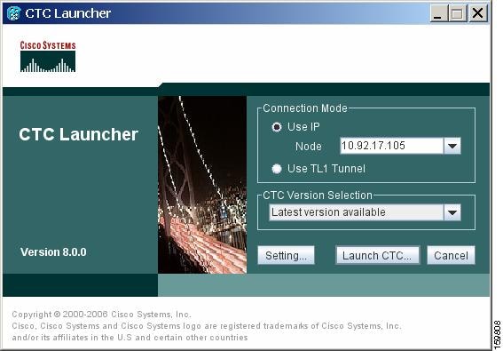
Step 3 ![]() In the Login Node box, enter the ONS NE node name or IP address. (If the address was entered previously, you can choose it from the drop-down menu.)
In the Login Node box, enter the ONS NE node name or IP address. (If the address was entered previously, you can choose it from the drop-down menu.)
Step 4 ![]() Select the CTC version you want to launch from the following choices in the drop-down menu:
Select the CTC version you want to launch from the following choices in the drop-down menu:
•![]() Same version as the login node: Select if you want to launch the same CTC version as the login node version, even if more recent versions of CTC are available in the cache.
Same version as the login node: Select if you want to launch the same CTC version as the login node version, even if more recent versions of CTC are available in the cache.
•![]() Latest version available: Select if you want to launch the latest CTC version available. If the cache has a newer CTC version than the login node, that CTC version will be used. Otherwise the same CTC version as the login node will be used.
Latest version available: Select if you want to launch the latest CTC version available. If the cache has a newer CTC version than the login node, that CTC version will be used. Otherwise the same CTC version as the login node will be used.
•![]() Version x.xx: Select if you want to launch a specific CTC version.
Version x.xx: Select if you want to launch a specific CTC version.

Note ![]() Cisco recommends that you always use the "Same version as the login node" unless the use of newer CTC versions is needed (for example, when CTC must manage a network containing mixed version NEs).
Cisco recommends that you always use the "Same version as the login node" unless the use of newer CTC versions is needed (for example, when CTC must manage a network containing mixed version NEs).
Step 5 ![]() Click Launch CTC. After the connection is made, the CTC Login dialog box appears.
Click Launch CTC. After the connection is made, the CTC Login dialog box appears.
Step 6 ![]() Log into the ONS node.
Log into the ONS node.
Note ![]() Because each CTC version requires particular JRE versions, the CTC Launcher will prompt the user for the location of a suitable JRE whenever a new CTC version is launched for the first time using a file chooser dialog (if a suitable JRE version is not known by the launcher yet). That JRE information is then saved in the user's preferences file. From the selection dialog, select any appropriate JRE directory.
Because each CTC version requires particular JRE versions, the CTC Launcher will prompt the user for the location of a suitable JRE whenever a new CTC version is launched for the first time using a file chooser dialog (if a suitable JRE version is not known by the launcher yet). That JRE information is then saved in the user's preferences file. From the selection dialog, select any appropriate JRE directory.
After the JRE version is selected, the CTC will be launched. The required jar files will be downloaded into the new cache if they are missing. The CTC Login window will appear after a few seconds.
Step 7 ![]() Return to your originating procedure (NTP).
Return to your originating procedure (NTP).
DLP-F402 Create a TL1 Tunnel Using the CTC Launcher
Step 1 ![]() Double-click the StartCTC.exe file.
Double-click the StartCTC.exe file.
Step 2 ![]() Click Use TL1 Tunnel.
Click Use TL1 Tunnel.
Step 3 ![]() In the Open CTC TL1 Tunnel dialog box, enter the following:
In the Open CTC TL1 Tunnel dialog box, enter the following:
•![]() Far End TID—Enter the TID of the ONS ENE at the far end of the tunnel. The TID is the name entered in the Node Name field on the node view Provisioning > General tab.
Far End TID—Enter the TID of the ONS ENE at the far end of the tunnel. The TID is the name entered in the Node Name field on the node view Provisioning > General tab.
•![]() Host Name/IP Address—Enter the GNE DNS host name or IP address through which the tunnel will established. This is the third-party vendor GNE that is connected to an ONS node through an OSI DCC network. CTC uses TCP/IP over a DCN to reach the GNE. The GNE accepts TL1 connections from the network and can forward TL1 traffic to the ENEs.
Host Name/IP Address—Enter the GNE DNS host name or IP address through which the tunnel will established. This is the third-party vendor GNE that is connected to an ONS node through an OSI DCC network. CTC uses TCP/IP over a DCN to reach the GNE. The GNE accepts TL1 connections from the network and can forward TL1 traffic to the ENEs.
•![]() Choose a port option:
Choose a port option:
–![]() Use Default TL1 Port—Choose this option if you want to use the default TL1 port 3081 and 3082.
Use Default TL1 Port—Choose this option if you want to use the default TL1 port 3081 and 3082.
–![]() Use Other TL1 Port—Choose this option if the GNE uses a different TL1 port. Enter the port number in the box next to the User Other TL1 Port radio button.
Use Other TL1 Port—Choose this option if the GNE uses a different TL1 port. Enter the port number in the box next to the User Other TL1 Port radio button.
•![]() TL1 Encoding Mode—Choose the TL1 encoding:
TL1 Encoding Mode—Choose the TL1 encoding:
–![]() LV + Binary Payload— TL1 messages are delimited by LV (length value) headers and TCP traffic is encapsulated in binary form. Cisco recommends this option because it is the most efficient encoding mode. However, you must verify that the GNE supports LV + Binary Payload encoding.
LV + Binary Payload— TL1 messages are delimited by LV (length value) headers and TCP traffic is encapsulated in binary form. Cisco recommends this option because it is the most efficient encoding mode. However, you must verify that the GNE supports LV + Binary Payload encoding.
–![]() LV + Base64 Payload— TL1 messages are delimited by LV headers and TCP traffic is encapsulated using Base64 encoding.
LV + Base64 Payload— TL1 messages are delimited by LV headers and TCP traffic is encapsulated using Base64 encoding.
–![]() Raw—TL1 messages are delimited by semi-columns only, and the TCP traffic is encapsulated using Base64 encoding.
Raw—TL1 messages are delimited by semi-columns only, and the TCP traffic is encapsulated using Base64 encoding.
•![]() GNE Login Required—Check this box if the GNE requires a a local TL1 ACT-USER login before forwarding TL1 traffic to ENEs.
GNE Login Required—Check this box if the GNE requires a a local TL1 ACT-USER login before forwarding TL1 traffic to ENEs.
•![]() TID—If the GNE Login Required box is checked, enter the GNE TID.
TID—If the GNE Login Required box is checked, enter the GNE TID.
Step 4 ![]() Click OK.
Click OK.
Step 5 ![]() If the GNE Login Required box is checked, complete the following steps. If not, continue Step 6.
If the GNE Login Required box is checked, complete the following steps. If not, continue Step 6.
a. ![]() In the Login to Gateway NE dialog box UID field, enter the TL1 user name.
In the Login to Gateway NE dialog box UID field, enter the TL1 user name.
b. ![]() In the PID field, enter the TL1 user password.
In the PID field, enter the TL1 user password.
c. ![]() Click OK.
Click OK.
Step 6 ![]() When the CTC Login dialog box appears, complete the CTC login.
When the CTC Login dialog box appears, complete the CTC login.
Step 7 ![]() Return to your originating procedure (NTP).
Return to your originating procedure (NTP).
DLP-F403 Create a TL1 Tunnel Using CTC
Purpose |
This task creates a TL1 tunnel using CTC. |
Tools/Equipment |
None |
Prerequisite Procedures |
|
Required/As Needed |
As needed |
Onsite/Remote |
Onsite or remote |
Security Level |
Provisioning or higher |
Step 1 ![]() From the Tools menu, choose Manage TL1 Tunnels.
From the Tools menu, choose Manage TL1 Tunnels.
Step 2 ![]() In the TL1 Tunnels window, click Create.
In the TL1 Tunnels window, click Create.
Step 3 ![]() In the Create CTC TL1 Tunnel dialog box, enter the following:
In the Create CTC TL1 Tunnel dialog box, enter the following:
•![]() Far End TID—Enter the TID of the ONS ENE at the far end of the tunnel. The ENE must be a Cisco ONS NE. The TID is the name entered in the Node Name field on the node view Provisioning > General tab.
Far End TID—Enter the TID of the ONS ENE at the far end of the tunnel. The ENE must be a Cisco ONS NE. The TID is the name entered in the Node Name field on the node view Provisioning > General tab.
•![]() Host Name/IP Address—Enter the GNE DNS host name or IP address through which the tunnel will established. This is the third-party vendor GNE that is connected to an ONS NE with an OSI DCC. CTC uses TCP/IP over a DCN to reach the GNE. The GNE accepts TL1 connections from the network and can forward TL1 traffic to the ENEs.
Host Name/IP Address—Enter the GNE DNS host name or IP address through which the tunnel will established. This is the third-party vendor GNE that is connected to an ONS NE with an OSI DCC. CTC uses TCP/IP over a DCN to reach the GNE. The GNE accepts TL1 connections from the network and can forward TL1 traffic to the ENEs.
•![]() Choose a port option:
Choose a port option:
–![]() Use Default TL1 Port—Choose this option if you want to use the GNE default TL1 port. TL1 uses standard ports, such as 3081 and 3082, unless custom TL1 ports are defined.
Use Default TL1 Port—Choose this option if you want to use the GNE default TL1 port. TL1 uses standard ports, such as 3081 and 3082, unless custom TL1 ports are defined.
–![]() Use Other TL1 Port—Choose this option if the GNE uses a different TL1 port. Enter the port number in the box next to the User Other TL1 Port radio button.
Use Other TL1 Port—Choose this option if the GNE uses a different TL1 port. Enter the port number in the box next to the User Other TL1 Port radio button.
•![]() TL1 Encoding Mode—Choose the TL1 encoding:
TL1 Encoding Mode—Choose the TL1 encoding:
–![]() LV + Binary Payload— TL1 messages are delimited by LV (length value) headers and TCP traffic is encapsulated in binary form. Cisco recommends this option because it is the most efficient. However, you must verify that the GNE supports LV + Binary Payload encoding.
LV + Binary Payload— TL1 messages are delimited by LV (length value) headers and TCP traffic is encapsulated in binary form. Cisco recommends this option because it is the most efficient. However, you must verify that the GNE supports LV + Binary Payload encoding.
–![]() LV + Base64 Payload— TL1 messages are delimited by LV headers and TCP traffic is encapsulated using Base64 encoding.
LV + Base64 Payload— TL1 messages are delimited by LV headers and TCP traffic is encapsulated using Base64 encoding.
–![]() Raw—TL1 messages are delimited by semi-columns only, and the TCP traffic is encapsulated using Base64 encoding.
Raw—TL1 messages are delimited by semi-columns only, and the TCP traffic is encapsulated using Base64 encoding.
•![]() GNE Login Required—Check this box if the GNE requires a a local TL1 ACT-USER login before forwarding TL1 traffic to ENEs.
GNE Login Required—Check this box if the GNE requires a a local TL1 ACT-USER login before forwarding TL1 traffic to ENEs.
•![]() TID—If the GNE Login Required box is checked, enter the GNE TID.
TID—If the GNE Login Required box is checked, enter the GNE TID.
Step 4 ![]() Click OK.
Click OK.
Step 5 ![]() If the GNE Login Required box is checked, complete the following steps. If not, continue Step 6.
If the GNE Login Required box is checked, complete the following steps. If not, continue Step 6.
a. ![]() In the Login to Gateway NE dialog box UID field, enter the TL1 user name.
In the Login to Gateway NE dialog box UID field, enter the TL1 user name.
b. ![]() In the PID field, enter the TL1 user password.
In the PID field, enter the TL1 user password.
c. ![]() Click OK.
Click OK.
Step 6 ![]() After the CTC Login dialog box appears, log into CTC.
After the CTC Login dialog box appears, log into CTC.
Step 7 ![]() Return to your originating procedure (NTP).
Return to your originating procedure (NTP).
DLP-F404 View TL1 Tunnel Information
Step 1 ![]() Log into CTC.
Log into CTC.
Step 2 ![]() From the Tools menu, choose Manage TL1 Tunnels.
From the Tools menu, choose Manage TL1 Tunnels.
Step 3 ![]() In the TL1 Tunnels window, view the information shown in Table 19-1.
In the TL1 Tunnels window, view the information shown in Table 19-1.
Step 4 ![]() Return to your originating procedure (NTP).
Return to your originating procedure (NTP).
DLP-F405 Edit a TL1 Tunnel Using CTC
Purpose |
This task edits a TL1 tunnel using CTC. |
Tools/Equipment |
None |
Prerequisite Procedures |
|
Required/As Needed |
As needed |
Onsite/Remote |
Onsite or remote |
Security Level |
Provisioning or higher |
Step 1 ![]() From the Tools menu, choose Manage TL1 Tunnels.
From the Tools menu, choose Manage TL1 Tunnels.
Step 2 ![]() In the TL1 Tunnels window, click the tunnel you want to edit.
In the TL1 Tunnels window, click the tunnel you want to edit.
Step 3 ![]() Click Edit.
Click Edit.
Step 4 ![]() In the Edit CTC TL1 Tunnel dialog box, edit the following:
In the Edit CTC TL1 Tunnel dialog box, edit the following:
•![]() Use Default TL1 Port—Choose this option if you want to use the GNE default TL1 port. TL1 uses standard ports, such as 3081 and 3082, unless custom TL1 ports are defined.
Use Default TL1 Port—Choose this option if you want to use the GNE default TL1 port. TL1 uses standard ports, such as 3081 and 3082, unless custom TL1 ports are defined.
•![]() Use Other TL1 Port—Choose this option if the GNE uses a different TL1 port. Enter the port number in the box next to the User Other TL1 Port radio button.
Use Other TL1 Port—Choose this option if the GNE uses a different TL1 port. Enter the port number in the box next to the User Other TL1 Port radio button.
•![]() TL1 Encoding Mode—Choose the TL1 encoding:
TL1 Encoding Mode—Choose the TL1 encoding:
–![]() LV + Binary Payload— TL1 messages are delimited by LV (length value) headers and TCP traffic is encapsulated in binary form. Cisco recommends this option because it is the most efficient. However, you must verify that the GNE supports LV + Binary Payload encoding.
LV + Binary Payload— TL1 messages are delimited by LV (length value) headers and TCP traffic is encapsulated in binary form. Cisco recommends this option because it is the most efficient. However, you must verify that the GNE supports LV + Binary Payload encoding.
–![]() LV + Base64 Payload— TL1 messages are delimited by LV headers and TCP traffic is encapsulated using Base64 encoding.
LV + Base64 Payload— TL1 messages are delimited by LV headers and TCP traffic is encapsulated using Base64 encoding.
–![]() Raw—TL1 messages are delimited by semi-columns only, and the TCP traffic is encapsulated using Base64 encoding.
Raw—TL1 messages are delimited by semi-columns only, and the TCP traffic is encapsulated using Base64 encoding.
•![]() GNE Login Required—Check this box if the GNE requires a a local TL1 ACT-USER login before forwarding TL1 traffic to ENEs.
GNE Login Required—Check this box if the GNE requires a a local TL1 ACT-USER login before forwarding TL1 traffic to ENEs.
•![]() TID—If the GNE Login Required box is checked, enter the GNE TID.
TID—If the GNE Login Required box is checked, enter the GNE TID.
Step 5 ![]() Click OK.
Click OK.
Step 6 ![]() If the GNE Login Required box is checked, complete login in the Login to Gateway NE dialog box. If not, continue Step 6.
If the GNE Login Required box is checked, complete login in the Login to Gateway NE dialog box. If not, continue Step 6.
a. ![]() In the UID field, enter the TL1 user name.
In the UID field, enter the TL1 user name.
b. ![]() In the PID field, enter the TL1 user password.
In the PID field, enter the TL1 user password.
c. ![]() Click OK.
Click OK.
Step 7 ![]() When the CTC Login dialog box appears, complete the CTC login. Refer to login procedures in the user documentation for the ONS ENE.
When the CTC Login dialog box appears, complete the CTC login. Refer to login procedures in the user documentation for the ONS ENE.
Step 8 ![]() Return to your originating procedure (NTP).
Return to your originating procedure (NTP).
DLP-F406 Delete a TL1 Tunnel Using CTC
Purpose |
This task deletes a TL1 tunnel using CTC. |
Tools/Equipment |
None |
Prerequisite Procedures |
|
Required/As Needed |
As needed |
Onsite/Remote |
Onsite or remote |
Security Level |
Provisioning or higher |
Step 1 ![]() From the Tools menu, choose Manage TL1 Tunnels.
From the Tools menu, choose Manage TL1 Tunnels.
Step 2 ![]() In the TL1 Tunnels window, click the tunnel you want to delete.
In the TL1 Tunnels window, click the tunnel you want to delete.
Step 3 ![]() Click Delete.
Click Delete.
Step 4 ![]() In the confirmation dialog box, click OK.
In the confirmation dialog box, click OK.
Step 5 ![]() Return to your originating procedure (NTP).
Return to your originating procedure (NTP).
DLP-F407 Create an SNMPv3 User
Purpose |
This procedure creates an SNMPv3 user. |
Tools/Equipment |
None |
Prerequisite Procedures |
|
Required/As Needed |
As needed |
Onsite/Remote |
Onsite |
Security Level |
Provisioning or higher |
Step 1 ![]() In node view, click the Provisioning > SNMP > SNMP V3 > User tabs.
In node view, click the Provisioning > SNMP > SNMP V3 > User tabs.
Step 2 ![]() Click Create.
Click Create.
Step 3 ![]() In the Create User dialog box, enter the following information:
In the Create User dialog box, enter the following information:
•![]() User Name—Specify the name of the user on the host that connects to the agent. The user name must be a minimum of six and a maximum of 20 alphanumeric (a-z, A-Z, 0-9) characters. For TL1 compatibility, the user name must be of 6 to 10 characters.
User Name—Specify the name of the user on the host that connects to the agent. The user name must be a minimum of six and a maximum of 20 alphanumeric (a-z, A-Z, 0-9) characters. For TL1 compatibility, the user name must be of 6 to 10 characters.
•![]() Group Name—Specify the group to which the user belongs.
Group Name—Specify the group to which the user belongs.
•![]() Authentication
Authentication
–![]() Protocol—Select the authentication algorithm that you want to use. The options are NONE, MD5, and SHA.
Protocol—Select the authentication algorithm that you want to use. The options are NONE, MD5, and SHA.
–![]() Password—Enter a password if you select MD5 or SHA. By default, the password length is set to a minimum of eight characters.
Password—Enter a password if you select MD5 or SHA. By default, the password length is set to a minimum of eight characters.
•![]() Privacy—Initiates a privacy authentication level setting session that enables the host to encrypt the contents of the message that is sent to the agent.
Privacy—Initiates a privacy authentication level setting session that enables the host to encrypt the contents of the message that is sent to the agent.
–![]() Protocol—Select NONE or DES as the privacy authentication algorithm.
Protocol—Select NONE or DES as the privacy authentication algorithm.
–![]() Password—Enter a password if you select DES.
Password—Enter a password if you select DES.
Step 4 ![]() Click OK to save the information.
Click OK to save the information.
Step 5 ![]() Return to your originating procedure (NTP).
Return to your originating procedure (NTP).
DLP-F408 Create MIB Views
Purpose |
This procedure creates an SNMPv3 MIB view. |
Tools/Equipment |
None |
Prerequisite Procedures |
|
Required/As Needed |
As needed |
Onsite/Remote |
Onsite |
Security Level |
Provisioning or higher |
Step 1 ![]() In node view, click the Provisioning > SNMP > SNMP V3 > MIB views tabs.
In node view, click the Provisioning > SNMP > SNMP V3 > MIB views tabs.
Step 2 ![]() Click Create.
Click Create.
Step 3 ![]() In the Create Views dialog box, enter the following information:
In the Create Views dialog box, enter the following information:
•![]() Name—Name of the view.
Name—Name of the view.
•![]() Subtree OID—The MIB subtree which, when combined with the mask, defines the family of subtrees.
Subtree OID—The MIB subtree which, when combined with the mask, defines the family of subtrees.
•![]() Bit Mask—A family of view subtrees. Each bit in the bit mask corresponds to a sub-identifier of the subtree OID.
Bit Mask—A family of view subtrees. Each bit in the bit mask corresponds to a sub-identifier of the subtree OID.
•![]() Type—Select the view type. Options are Include and Exclude. Type defines whether the family of subtrees that are defined by the subtree OID and the bit mask combination are included or excluded from the notification filter.
Type—Select the view type. Options are Include and Exclude. Type defines whether the family of subtrees that are defined by the subtree OID and the bit mask combination are included or excluded from the notification filter.
Step 4 ![]() Click OK to save the information.
Click OK to save the information.
Step 5 ![]() Return to your originating procedure (NTP).
Return to your originating procedure (NTP).
DLP-F409 Create Group Access
Step 1 ![]() In node view, click the Provisioning > SNMP > SNMP V3 > Group Access tabs.
In node view, click the Provisioning > SNMP > SNMP V3 > Group Access tabs.
Step 2 ![]() Click Create.
Click Create.
Step 3 ![]() In the Create Group Access dialog box, enter the following information:
In the Create Group Access dialog box, enter the following information:
•![]() Group Name—The name of the SNMP group, or collection of users, who share a common access policy.
Group Name—The name of the SNMP group, or collection of users, who share a common access policy.
•![]() Security Level—The security level for which the access parameters are defined. Select from the following options:
Security Level—The security level for which the access parameters are defined. Select from the following options:
–![]() noAuthNoPriv—Uses a user name match for authentication.
noAuthNoPriv—Uses a user name match for authentication.
–![]() AuthNoPriv—Provides authentication based on the HMAC-MD5 or HMAC-SHA algorithms.
AuthNoPriv—Provides authentication based on the HMAC-MD5 or HMAC-SHA algorithms.
–![]() AuthPriv—Provides authentication based on the HMAC-MD5 or HMAC-SHA algorithms. Provides DES 56-bit encryption based on the CBC-DES (DES-56) standard, in addition to authentication.
AuthPriv—Provides authentication based on the HMAC-MD5 or HMAC-SHA algorithms. Provides DES 56-bit encryption based on the CBC-DES (DES-56) standard, in addition to authentication.
If you select authNoPriv or authPriv for a group, the corresponding user must be configured with an authentication protocol and password, with privacy protocol and password, or both.
•![]() Views
Views
–![]() Read View Name—Read view name for the group.
Read View Name—Read view name for the group.
–![]() Notify View Name—Notify view name for the group.
Notify View Name—Notify view name for the group.
•![]() Allow SNMP Sets—Select this check box if you want the SNMP agent to accept SNMP SET requests. If this check box is not selected, SET requests are rejected.
Allow SNMP Sets—Select this check box if you want the SNMP agent to accept SNMP SET requests. If this check box is not selected, SET requests are rejected.
Note ![]() SNMP SET request access is implemented for very few objects.
SNMP SET request access is implemented for very few objects.
Step 4 ![]() Click OK to save the information.
Click OK to save the information.
Step 5 ![]() Return to your originating procedure (NTP).
Return to your originating procedure (NTP).
DLP-F410 Configure SNMPv3 Trap Destination
Purpose |
This procedure provisions SNMPv3 trap destination. |
Tools/Equipment |
None |
Prerequisite Procedures |
|
Required/As Needed |
As needed |
Onsite/Remote |
Onsite |
Security Level |
Provisioning or higher |
Step 1 ![]() In node view, click the Provisioning > SNMP > SNMP V3 > Trap Destinations (V3) tabs.
In node view, click the Provisioning > SNMP > SNMP V3 > Trap Destinations (V3) tabs.
Step 2 ![]() Click Create.
Click Create.
Step 3 ![]() In the Configure SNMPv3 Trap dialog box, enter the following information:
In the Configure SNMPv3 Trap dialog box, enter the following information:
•![]() Target Address—Target to which the traps should be sent. Use an IPv4 or an IPv6 address.
Target Address—Target to which the traps should be sent. Use an IPv4 or an IPv6 address.
•![]() UDP Port—UDP port number that the host uses. Default value is 162.
UDP Port—UDP port number that the host uses. Default value is 162.
•![]() User Name—Specify the name of the user on the host that connects to the agent.
User Name—Specify the name of the user on the host that connects to the agent.
•![]() Security Level—Select one of the following options:
Security Level—Select one of the following options:
–![]() noAuthNoPriv—Uses a user name match for authentication.
noAuthNoPriv—Uses a user name match for authentication.
–![]() AuthNoPriv—Provides authentication based on the HMAC-MD5 or HMAC-SHA algorithms.
AuthNoPriv—Provides authentication based on the HMAC-MD5 or HMAC-SHA algorithms.
–![]() AuthPriv—Provides authentication based on the HMAC-MD5 or HMAC-SHA algorithms. Provides DES 56-bit encryption based on the CBC-DES (DES-56) standard, in addition to authentication.
AuthPriv—Provides authentication based on the HMAC-MD5 or HMAC-SHA algorithms. Provides DES 56-bit encryption based on the CBC-DES (DES-56) standard, in addition to authentication.
•![]() Filter Profile—Select this check box and enter the filter profile name. Traps are sent only if you provide a filter profile name and create a notification filter. This field is optional and traps can also be sent without providing a filter profile and create a notification filter. For more information, see "DLP-F412 Create Notification Filters" task.
Filter Profile—Select this check box and enter the filter profile name. Traps are sent only if you provide a filter profile name and create a notification filter. This field is optional and traps can also be sent without providing a filter profile and create a notification filter. For more information, see "DLP-F412 Create Notification Filters" task.
•![]() Proxy Traps Only—If selected, forwards only proxy traps from the ENE. Traps from this node are not sent to the trap destination identified by this entry.
Proxy Traps Only—If selected, forwards only proxy traps from the ENE. Traps from this node are not sent to the trap destination identified by this entry.
•![]() Proxy Tags—Specify a list of tags. The tag list is needed on a GNE only if an ENE needs to send traps to the trap destination identified by this entry, and wants to use the GNE as the proxy.
Proxy Tags—Specify a list of tags. The tag list is needed on a GNE only if an ENE needs to send traps to the trap destination identified by this entry, and wants to use the GNE as the proxy.
Step 4 ![]() Click OK to save the information.
Click OK to save the information.
Step 5 ![]() Return to your originating procedure (NTP).
Return to your originating procedure (NTP).
DLP-F411 Delete SNMPv3 Trap Destination
Purpose |
This procedure deletes an SNMPv3 trap destination. |
Tools/Equipment |
None |
Prerequisite Procedures |
|
Required/As Needed |
As needed |
Onsite/Remote |
Onsite |
Security Level |
Provisioning or higher |
Step 1 ![]() In node view, click the Provisioning > SNMP> SNMPv3 > Trap Destination tabs.
In node view, click the Provisioning > SNMP> SNMPv3 > Trap Destination tabs.
Step 2 ![]() In the Trap Destinations area, select the trap destination you want to delete.
In the Trap Destinations area, select the trap destination you want to delete.
Step 3 ![]() Click Delete. A confirmation dialog box appears.
Click Delete. A confirmation dialog box appears.
Step 4 ![]() Click Yes.
Click Yes.
Step 5 ![]() Return to your originating procedure (NTP).
Return to your originating procedure (NTP).
DLP-F412 Create Notification Filters
Step 1 ![]() In node view, click the Provisioning > SNMP > SNMP V3 > Notification Filters tabs.
In node view, click the Provisioning > SNMP > SNMP V3 > Notification Filters tabs.
Step 2 ![]() Click Create.
Click Create.
Step 3 ![]() In the Create Notify dialog box, enter the following information:
In the Create Notify dialog box, enter the following information:
•![]() Filter Profile Name—Specify a name for the filter.
Filter Profile Name—Specify a name for the filter.
•![]() Subtree OID—The MIB subtree which, when combined with the mask, defines the family of subtrees.
Subtree OID—The MIB subtree which, when combined with the mask, defines the family of subtrees.
•![]() Bit Mask—A family of view subtrees. Each bit in the bit mask corresponds to a sub-identifier of the subtree OID.
Bit Mask—A family of view subtrees. Each bit in the bit mask corresponds to a sub-identifier of the subtree OID.
•![]() View Type—Select the view type. Options are Include and Exclude. Type defines whether the family of subtrees that are defined by the subtree OID and the bit mask combination are included or excluded from the notification filter.
View Type—Select the view type. Options are Include and Exclude. Type defines whether the family of subtrees that are defined by the subtree OID and the bit mask combination are included or excluded from the notification filter.
Step 4 ![]() Click OK to save the information.
Click OK to save the information.
Step 5 ![]() Return to your originating procedure (NTP).
Return to your originating procedure (NTP).
DLP-F413 Manually Configure the SNMPv3 Proxy Forwarder Table
Step 1 ![]() In network view, click Provisioning > SNMPv3.
In network view, click Provisioning > SNMPv3.
Step 2 ![]() In the SNMPv3 Proxy Server area, complete the following:
In the SNMPv3 Proxy Server area, complete the following:
•![]() Select the GNE to be used as the SNMPv3 proxy server from the drop-down list.
Select the GNE to be used as the SNMPv3 proxy server from the drop-down list.
•![]() Select the Enable IPv6 Target/Trap check box if the nodes and the NMS stations are on an IPv6 network.
Select the Enable IPv6 Target/Trap check box if the nodes and the NMS stations are on an IPv6 network.
Step 3 ![]() In the SNMPv3 Proxy Forwarder Table area, click Manual Create.
In the SNMPv3 Proxy Forwarder Table area, click Manual Create.
Step 4 ![]() In the Manual Configuration of SNMPv3 Proxy Forwarder dialog box, enter the following information:
In the Manual Configuration of SNMPv3 Proxy Forwarder dialog box, enter the following information:
•![]() Target IP Address—Target to which the request should be forwarded. Use an IPv4 or an IPv6 address.
Target IP Address—Target to which the request should be forwarded. Use an IPv4 or an IPv6 address.
•![]() Context Engine ID—The context engine ID of the ENE to which the request is to be forwarded. The context engine ID should be the same as the context engine ID of the incoming request.
Context Engine ID—The context engine ID of the ENE to which the request is to be forwarded. The context engine ID should be the same as the context engine ID of the incoming request.
•![]() Proxy Type—Type of SNMP request that needs to be forwarded. The options are Read and Write.
Proxy Type—Type of SNMP request that needs to be forwarded. The options are Read and Write.
•![]() Local User Details—The details of the local user who proxies on behalf of the ENE user.
Local User Details—The details of the local user who proxies on behalf of the ENE user.
–![]() User Name—Specify the name of the user on the host that connects to the agent.
User Name—Specify the name of the user on the host that connects to the agent.
–![]() Local Security Level—Select the security level of the incoming requests that are to be forwarded. The options are noAuthNoPriv, AuthNoPriv, and AuthPriv.
Local Security Level—Select the security level of the incoming requests that are to be forwarded. The options are noAuthNoPriv, AuthNoPriv, and AuthPriv.
•![]() Remote User Details—User to which the request is forwarded.
Remote User Details—User to which the request is forwarded.
–![]() User Name—Specify the user name of the remote user.
User Name—Specify the user name of the remote user.
–![]() Remote Security Level—Select the security level of the outgoing requests. The options are noAuthNoPriv, AuthNoPriv, and AuthPriv.
Remote Security Level—Select the security level of the outgoing requests. The options are noAuthNoPriv, AuthNoPriv, and AuthPriv.
•![]() Authentication
Authentication
–![]() Protocol—Select the authentication algorithm you want to use. The options are NONE, MD5, and SHA.
Protocol—Select the authentication algorithm you want to use. The options are NONE, MD5, and SHA.
–![]() Password—Enter the password if you select MD5 or SHA.
Password—Enter the password if you select MD5 or SHA.
•![]() Privacy—Enables the host to encrypt the contents of the message that is sent to the agent.
Privacy—Enables the host to encrypt the contents of the message that is sent to the agent.
–![]() Protocol—Select NONE or DES as the privacy authentication algorithm.
Protocol—Select NONE or DES as the privacy authentication algorithm.
–![]() Password—Enter the password if you select DES. The password should not exceed 64 characters.
Password—Enter the password if you select DES. The password should not exceed 64 characters.
Step 5 ![]() Click OK to save the information.
Click OK to save the information.
Step 6 ![]() Return to your originating procedure (NTP).
Return to your originating procedure (NTP).
DLP-F414 Automatically Configure the SNMPv3 Proxy Forwarder Table
Step 1 ![]() In network view, click Provisioning > SNMPv3 tabs.
In network view, click Provisioning > SNMPv3 tabs.
Step 2 ![]() In the SNMPv3 Proxy Server area, complete the following:
In the SNMPv3 Proxy Server area, complete the following:
•![]() Select the GNE to be used as the SNMPv3 proxy server from the drop-down list.
Select the GNE to be used as the SNMPv3 proxy server from the drop-down list.
•![]() Select the Enable IPv6 Target/Trap check box if the nodes and the NMS stations are on an IPv6 network.
Select the Enable IPv6 Target/Trap check box if the nodes and the NMS stations are on an IPv6 network.
Step 3 ![]() In the SNMPv3 Proxy Forwarder Table area, click Auto Create.
In the SNMPv3 Proxy Forwarder Table area, click Auto Create.
Step 4 ![]() In the Automatic Configuration of SNMPv3 Proxy Forwarder dialog box, enter the following information:
In the Automatic Configuration of SNMPv3 Proxy Forwarder dialog box, enter the following information:
•![]() Proxy Type—Select the type of proxies to be forwarded. The options are Read and Write.
Proxy Type—Select the type of proxies to be forwarded. The options are Read and Write.
•![]() Security Level—Select the security level for the incoming requests that are to be forwarded. The options are:
Security Level—Select the security level for the incoming requests that are to be forwarded. The options are:
–![]() noAuthNoPriv—Uses a username match for authentication.
noAuthNoPriv—Uses a username match for authentication.
–![]() AuthNoPriv—Provides authentication based on the HMAC-MD5 or HMAC-SHA algorithms.
AuthNoPriv—Provides authentication based on the HMAC-MD5 or HMAC-SHA algorithms.
–![]() AuthPriv—Provides authentication based on the HMAC-MD5 or HMAC-SHA algorithms. Provides DES 56-bit encryption based on the CBC-DES (DES-56) standard, in addition to authentication.
AuthPriv—Provides authentication based on the HMAC-MD5 or HMAC-SHA algorithms. Provides DES 56-bit encryption based on the CBC-DES (DES-56) standard, in addition to authentication.
•![]() Target Address List—Select the proxy destination.
Target Address List—Select the proxy destination.
•![]() Local User Name—Select the user name from the list of users.
Local User Name—Select the user name from the list of users.
Note ![]() When you configure SNMPv3 Proxy Forwarder Table automatically, the default_group is used on the ENE. The default_group does not have write access. To enable write access and allow SNMP sets, you need to edit the default_group on ENE.
When you configure SNMPv3 Proxy Forwarder Table automatically, the default_group is used on the ENE. The default_group does not have write access. To enable write access and allow SNMP sets, you need to edit the default_group on ENE.
Step 5 ![]() Click OK to save the settings.
Click OK to save the settings.
Step 6 ![]() Return to your originating procedure (NTP).
Return to your originating procedure (NTP).
DLP-F415 Manually Configure the SNMPv3 Proxy Trap Forwarder Table
Step 1 ![]() In network view, click Provisioning > SNMPv3 tabs.
In network view, click Provisioning > SNMPv3 tabs.
Step 2 ![]() In the SNMPv3 Proxy Server area, complete the following:
In the SNMPv3 Proxy Server area, complete the following:
•![]() Select the GNE to be used as the SNMPv3 proxy server from the drop-down list.
Select the GNE to be used as the SNMPv3 proxy server from the drop-down list.
•![]() Select the Enable IPv6 Target/Trap check box if the nodes and the NMS stations are on an IPv6 network.
Select the Enable IPv6 Target/Trap check box if the nodes and the NMS stations are on an IPv6 network.
Step 3 ![]() In the SNMPv3 Proxy Trap Forwarder Table area, click Manual Create.
In the SNMPv3 Proxy Trap Forwarder Table area, click Manual Create.
Step 4 ![]() In the Manual Configuration of SNMPv3 Proxy Trap Forwarder dialog box, enter the following information:
In the Manual Configuration of SNMPv3 Proxy Trap Forwarder dialog box, enter the following information:
•![]() Remote Trap Source—Select the IP address from which the traps are sent. If the IP address is not listed, enter the IP address manually.
Remote Trap Source—Select the IP address from which the traps are sent. If the IP address is not listed, enter the IP address manually.
•![]() Context Engine ID—Specify the context engine ID of the ENE from which traps need to be forwarded. This field is automatically populated if the source of trap is selected. If the source of trap is not specified, you need to manually enter the context engine ID.
Context Engine ID—Specify the context engine ID of the ENE from which traps need to be forwarded. This field is automatically populated if the source of trap is selected. If the source of trap is not specified, you need to manually enter the context engine ID.
•![]() Target Tag—Specify the tag name. The tag identifies the list of NMS that should receive the forwarded traps. Traps are forwarded to all GNE Trap destinations whose proxy tags list contains this tag.
Target Tag—Specify the tag name. The tag identifies the list of NMS that should receive the forwarded traps. Traps are forwarded to all GNE Trap destinations whose proxy tags list contains this tag.
•![]() Remote User Details
Remote User Details
–![]() User Name—Specify the user name.
User Name—Specify the user name.
–![]() Security Level—Select the security level for the user. The options are noAuthNoPriv, AuthNoPriv, and AuthPriv.
Security Level—Select the security level for the user. The options are noAuthNoPriv, AuthNoPriv, and AuthPriv.
•![]() Authentication—Select the authentication algorithm.
Authentication—Select the authentication algorithm.
–![]() Protocol—Select the authentication algorithm you want to use. The options are NONE, MD5, and SHA. Default is None.
Protocol—Select the authentication algorithm you want to use. The options are NONE, MD5, and SHA. Default is None.
–![]() Password—Enter the password if you select MD5 or SHA.
Password—Enter the password if you select MD5 or SHA.
•![]() Privacy—Enables the host to encrypt the contents of the message that is sent to the agent.
Privacy—Enables the host to encrypt the contents of the message that is sent to the agent.
–![]() Protocol—Select NONE or DES as the privacy authentication algorithm. Encryption is disabled if NONE is selected.
Protocol—Select NONE or DES as the privacy authentication algorithm. Encryption is disabled if NONE is selected.
–![]() Password—Enter the password if you select DES. The password should not exceed 64 characters.
Password—Enter the password if you select DES. The password should not exceed 64 characters.
Step 5 ![]() Click OK to save the information.
Click OK to save the information.
Step 6 ![]() Return to your originating procedure (NTP).
Return to your originating procedure (NTP).
DLP-F416 Automatically Configure the SNMPv3 Proxy Trap Forwarder Table
Step 1 ![]() In network view, click Provisioning > SNMPv3 tabs.
In network view, click Provisioning > SNMPv3 tabs.
Step 2 ![]() In the SNMPv3 Proxy Server area, complete the following:
In the SNMPv3 Proxy Server area, complete the following:
•![]() Select the GNE to be used as the SNMPv3 proxy server from the drop-down list.
Select the GNE to be used as the SNMPv3 proxy server from the drop-down list.
•![]() Select the Enable IPv6 Target/Trap check box if the nodes and the NMS stations are on an IPv6 network.
Select the Enable IPv6 Target/Trap check box if the nodes and the NMS stations are on an IPv6 network.
Step 3 ![]() In the SNMPv3 Proxy Trap Forwarder Table area, click Auto Create.
In the SNMPv3 Proxy Trap Forwarder Table area, click Auto Create.
Step 4 ![]() In the Automatic Configuration of SNMPv3 Proxy Trap Forwarder dialog box, enter the following information:
In the Automatic Configuration of SNMPv3 Proxy Trap Forwarder dialog box, enter the following information:
•![]() Target Tag—Specify the tag name. The tag identifies the list of NMS that should receive the forwarded traps. All GNE Trap destinations that have this tag in their proxy tags list are chosen.
Target Tag—Specify the tag name. The tag identifies the list of NMS that should receive the forwarded traps. All GNE Trap destinations that have this tag in their proxy tags list are chosen.
•![]() Source of Trap—The list of ENEs whose traps are forwarded to the SNMPv3 Trap destinations that are identified by the Target Tag.
Source of Trap—The list of ENEs whose traps are forwarded to the SNMPv3 Trap destinations that are identified by the Target Tag.
Step 5 ![]() Click OK to save the information.
Click OK to save the information.
Step 6 ![]() Return to your originating procedure (NTP).
Return to your originating procedure (NTP).
DLP-F417 Repair Server Trails
Note ![]() The Server Trail Repair wizard can only fix the IP address changes and cannot fix Server Trail terminations when you migrate from IPv4 to IPv6 addresses.
The Server Trail Repair wizard can only fix the IP address changes and cannot fix Server Trail terminations when you migrate from IPv4 to IPv6 addresses.
Note ![]() The Server Trail Repair wizard cannot repair the Server Trails when IP address of nodes on both ends of the Server Trail are changed.
The Server Trail Repair wizard cannot repair the Server Trails when IP address of nodes on both ends of the Server Trail are changed.
Note ![]() When Server Trails are created on an IPv4 or IPv6 node and the IP address of the node changes, make sure that the Server Trail Repair wizard is launched on the IP address of the node that changed. For example, if the IP address of Server Trails created on an IPv4 node changes, run the Server Trail Repair wizard on the IPv4 node and not on the IPv6 node.
When Server Trails are created on an IPv4 or IPv6 node and the IP address of the node changes, make sure that the Server Trail Repair wizard is launched on the IP address of the node that changed. For example, if the IP address of Server Trails created on an IPv4 node changes, run the Server Trail Repair wizard on the IPv4 node and not on the IPv6 node.
Step 1 ![]() Complete the "DLP-F181 Log into CTC" task on page 16-32 at the node where you will repair Server Trails. If you are already logged in, continue with Step 2.
Complete the "DLP-F181 Log into CTC" task on page 16-32 at the node where you will repair Server Trails. If you are already logged in, continue with Step 2.
Note ![]() The Server Trail Repair wizard works only when nodes at both ends of the Server Trail are added in the CTC. If CTC is launched after the IP address is changed or if the node on any of the sides is not discovered automatically, then the node has to be added manually into the CTC.
The Server Trail Repair wizard works only when nodes at both ends of the Server Trail are added in the CTC. If CTC is launched after the IP address is changed or if the node on any of the sides is not discovered automatically, then the node has to be added manually into the CTC.
Step 2 ![]() From the View menu, choose Go to Network View.
From the View menu, choose Go to Network View.
Step 3 ![]() Choose the Tools > Links > Repair Server Trails option from the tool bar.
Choose the Tools > Links > Repair Server Trails option from the tool bar.
The Server Trail Repair wizard appears.
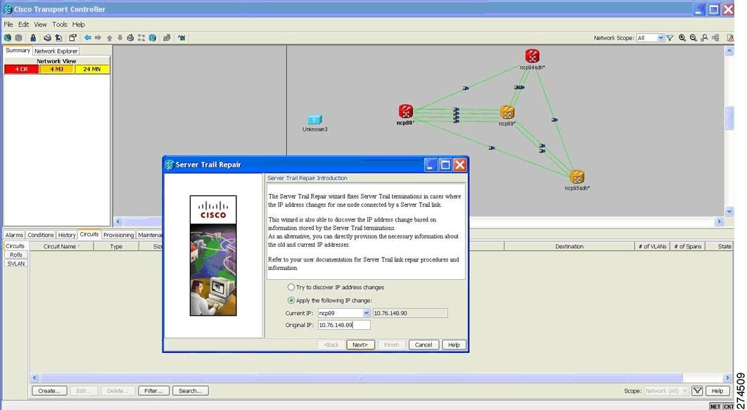
Step 4 ![]() Specify the changed IP address.
Specify the changed IP address.
The Server Trail Repair window provides the following options, as shown in Figure 19-2:
Figure 19-2 Server Trail Repair Wizard—Server Trail Repair Introduction
•![]() Try to discover IP address changes—The wizard searches and displays the list of changed IP addresses.
Try to discover IP address changes—The wizard searches and displays the list of changed IP addresses.
Note ![]() The wizard can discover multiple IP address changes. However, the wizard can repair only one IP address change at a time. To repair multiple IP address changes, run the Server Trail Repair wizard multiple times.
The wizard can discover multiple IP address changes. However, the wizard can repair only one IP address change at a time. To repair multiple IP address changes, run the Server Trail Repair wizard multiple times.
•![]() Apply the following IP change—Allows you to specify the changed IP address.
Apply the following IP change—Allows you to specify the changed IP address.
Select the node with changed IP address and specify old IP address as Original IP Address. The wizard automatically displays the current IP address.
Step 5 ![]() Click Next.
Click Next.
If you selected "Try to discover IP address changes" option in Step 4, then the wizard displays all the IP address changes that will be fixed, as shown in Figure 19-3. Click Next.
Figure 19-3 Server Trail Repair Wizard—Discover IP Change
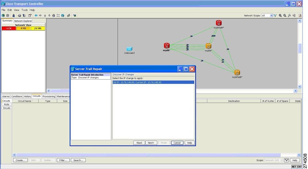
If you selected "Apply the following IP change" option in Step 4, continue with Step 6.
Step 6 ![]() The Server Trail Terminations to Repair window appears, as shown in Figure 19-4. Click Finish to repair the Server Trails.
The Server Trail Terminations to Repair window appears, as shown in Figure 19-4. Click Finish to repair the Server Trails.
Figure 19-4 Server Trail Repair Wizard—Server Trail Terminations to Repair
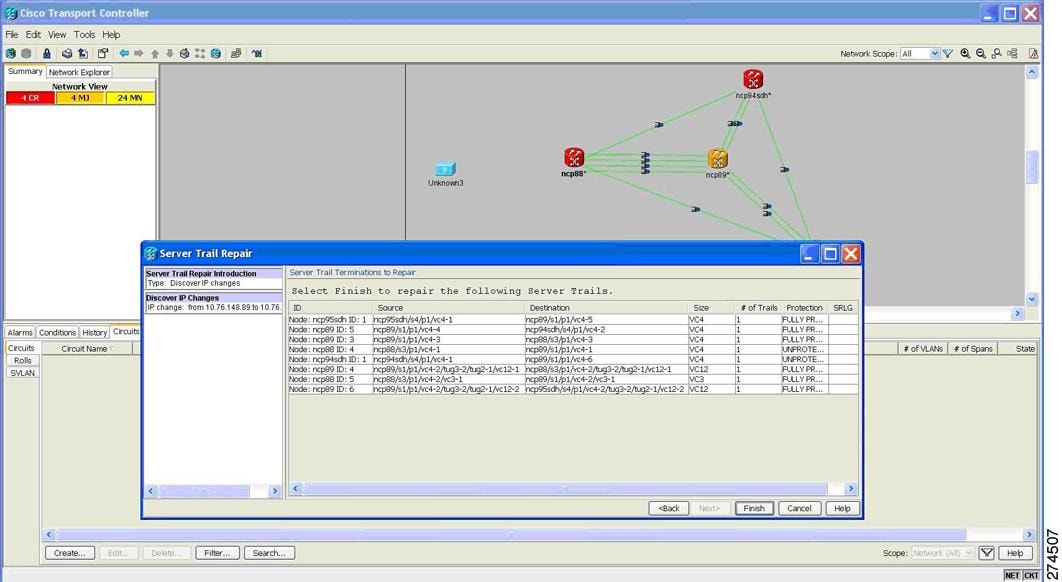
Stop. You have completed this procedure.
 Feedback