Manage the Node
This document explains how to modify node provisioning for the Cisco ONS 15454 and perform common management tasks such as monitoring the dense wavelength division multiplexing (DWDM) automatic power control (APC) and span loss values. To provision a new node, see the chapter, "Turn Up a Node" in the Cisco ONS 15454 DWDM Configuration Guide. To change default network element (NE) settings and to view a list of those settings, refer to the Network Element Defaults document.
 Note |
The procedures and tasks described in this chapter for the Cisco ONS 15454 platform is applicable to the Cisco ONS 15454 M2 and Cisco ONS 15454 M6 platforms, unless noted otherwise. |
Note |
Unless otherwise specified, "ONS 15454" refers to both ANSI and ETSI shelf assemblies. |
Revision History
|
Date |
Notes |
|---|---|
|
June 2023 |
Added the following procedures for R11.1.3:
|
|
May 2020 |
Updated the "NTP-G357 Perform OTDR Scan and OTDR Event Scan" procedure for R11.1.1.2. |
|
December 2017 |
Updated the "DLP-G786 Perform OTDR Scan on TNCS-O Cards" and "DLP-G787 Perform OTDR Event Scan on TNCS-O Cards" procedures for R10.8. |
|
March 2017 |
Updated the "DLP-G787 Perform OTDR Event Scan on TNCS-O Card" procedure for R10.6.2. |
|
November 2016 |
Added the section, "System Mode Conversion". |
|
January 2016 |
Updated the following procedures:
|
|
November 2014 |
Added the section "DLP-G776 Configure the Node for TACACS+ Authentication". |
|
October 2011 |
Updated the section "DLP-G281 Configure the Node for RADIUS Authentication". |
|
December 2011 |
Updated the following procedures:
|
Before You Begin
Before performing the following procedures, investigate all alarms and clear any trouble conditions. Refer to the Cisco ONS 15454 DWDM Troubleshooting Guide as necessary.
This section lists the procedures (NTPs). Turn to a procedure for applicable tasks (DLPs).
-
NTP-G357 Perform OTDR Scan and OTDR Event Scan—Complete this procedure as needed to perform OTDR scan and OTDR event scan.
-
NTP-G76 Verify Optical Span Loss Using CTC—Complete this procedure as needed to view or modify the DWDM span loss values.
-
NTP-G77 Manage Automatic Power Control—Complete this procedure as needed to manage the DWDM APC.
-
NTP-G78 View Side Power Monitoring—Complete this procedure as needed to view and update a reconfigurable optical add/drop multiplexing (ROADM) node's power equalization.
-
NTP-G80 Change Node Management Information—Complete this procedure as needed to change node name, contact information, latitude, longitude, date, time, and login legal disclaimer.
-
NTP-G134 Modify OSI Provisioning—Complete this procedure as needed to modify Open System Interconnection (OSI) parameters including the OSI routing mode, Target Identifier Address Resolution Protocol (TARP), routers, subnets, and IP-over-connectionless network service (CLNS) tunnels.
-
NTP-G81 Change CTC Network Access—Complete this procedure as needed to change the IP address, default router, subnet mask, network configuration settings, and static routes.
-
NTP-G82 Customize the CTC Network View—Complete this procedure as needed to create domains and customize the appearance of the network map, including specifying a different default map, creating domains, consolidating links in the network view, selecting your own map or image, and changing the background color.
-
NTP-G83 Modify or Delete Card Protection Settings—Complete this procedure as needed.
-
NTP-G84 Initiate and Clear Y-Cable and Splitter External Switching Commands—Complete this procedure as needed.
-
NTP-G85 Modify or Delete OSC Terminations, DCC/GCC Terminations, and Provisionable Patchcords—Complete this procedure as needed to modify or delete generic communications channel (GCC) terminations, optical service channel (OSC) terminations, and provisionable patchcords.
-
NTP-G86 Convert a Pass-Through Connection to Add/Drop Connections—Complete this procedure as needed to convert a pass-through connection to an add/drop connection.
-
NTP-G87 Change Node Timing Parameters—Complete this procedure as needed.
-
NTP-G88 Modify Users and Change Security—Complete this procedure as needed to make changes to user settings, including security level and security policies, and to delete users.
-
NTP-G89 Change SNMP Settings—Complete this procedure as needed.
System Mode Conversion
The system mode can be changed from ANSI (SONET) to ETSI (SDH) or vice-versa. Changing the system mode removes the provisioned data and the system reverts to the default configuration.
This is available on the single controller and dual controller cards. The node can be in a standalone or multishelf configuration.
-
"SHELF-COMM-FAIL" alarm is present
-
any SSC is in limited state
-
ONS 15454 chassis is present as a part of the multishelf set-up
DLP-G796 Change System Mode Using CTC
This task enables the user to change the system mode using CTC.
|
Purpose |
This task enables the user to change the System Mode. |
|
Tools/Equipment |
None |
|
Prerequisite Procedures |
|
|
Required/As Needed |
As needed |
|
Onsite/Remote |
Onsite or remote |
|
Security Level |
Superuser only |
Procedure
|
Step 1 |
In tab view, click the tabs. |
|
Step 2 |
In the System Mode area, the current System Mode is displayed (ETSI or ANSI). |
|
Step 3 |
Click the Change System Mode tab to change the system mode. If the system is currently in ANSI mode, the system mode is changed to ETSI, or vice-versa. |
|
Step 4 |
To proceed with the mode change, click Yes on the displayed pop-up. |
What to do next
Start a new CTC session and check the system mode.
NTP-G357 Perform OTDR Scan and OTDR Event Scan
|
Purpose |
This task allows you to perform OTDR scan and OTDR event scan and displays the scan details in graphical format. |
|
Tools/Equipment |
None |
|
Prerequisite Procedures |
|
|
Required/As Needed |
As needed |
|
Onsite/Remote |
Onsite or remote |
|
Security Level |
Provisioning or higher |
Procedure
|
Perform any of the following tasks as needed: Stop. You have completed this procedure. |
DLP-G786 Perform OTDR Scan
|
Purpose |
This task allows you to perform a hybrid or fast OTDR scan and displays the scan details in graphical format. |
|
Tools/Equipment |
TNCS-O or TNCS-2O card |
|
Prerequisite Procedures |
|
|
Required/As Needed |
As needed |
|
Onsite/Remote |
Onsite or remote |
|
Security Level |
Provisioning or higher |
Note |
When the optical side is not configured, the user could start the OTDR scan on that fiber. However, the user must ensure that the far end of the fiber has no OSC in service. |
Procedure
|
Step 1 |
In the node view, click the tabs. |
||||||||||||||||||||||||
|
Step 2 |
From the OTDR Port drop-down list, choose the port on which you want to perform the scan.
|
||||||||||||||||||||||||
|
Step 3 |
Click Line Rx or Line Tx tabs. |
||||||||||||||||||||||||
|
Step 4 |
From the Sector drop-down list, choose a sector to perform the scan. The OTDR scan parameters such as Capture Start Point, Capture End Point, Pulse Width, Measure Time, and Resolution can be
configured by user in Expert sector. For all other sectors, the above parameters are provided as predefined set of values.
In case of Expert sector, these parameters can be configured in OTDR configuration panel, for every OTDR port.
|
||||||||||||||||||||||||
|
Step 5 |
Choose Base Scan or Last Scan. When the last scan and baseline configurations differ, the last scan details are displayed on the graph. Choose Base Scan in the drop-down list to view the baseline scan. |
||||||||||||||||||||||||
|
Step 6 |
Click Hybrid Scan or Fast Scan from the Manual Scan area to start an OTDR scan manually. Fast scan trace is displayed to the user for quick reference before the composite trace. It is displayed at the end of OTDR training operation and before start of the composite trace. A progress bar is provided to the user for each scan in the sector that displays the percentage of execution of the entire scan operation. In R10.8, auto sector is substituted with the composite trace. The composite trace is stitched through scans executed on legacy zones (1km, 25km, 80km, 100km). The composite trace is provided only when OTDR training is successfully executed. When you start a fast scan on the RX port, an OTDR-FAST-SCAN-IN-PROGRESS-RX alarm is raised. When you start a fast scan on the TX port, an OTDR-FAST-SCAN-IN-PROGRESS-TX alarm is raised. The fast scan shuts down the OSC channel.
When you start a Hybrid scan on the RX port, an OTDR-HYBRID-SCAN-IN-PROGRESS-RX condition is raised. When you start a Hybrid scan on the TX port, an OTDR-HYBRID-SCAN-IN-PROGRESS-TX condition is raised. Hybrid scan does not shut down the OSC channel and takes longer time to complete. The alarms are raised at both near-end and far-end if the OSC link is established. If no OSC link is up, then the alarms are
raised only at the near-end.
In case of EDRA, When you start a Fast scan on the RX port, an OTDR-FAST-SCAN-IN-PROGRESS-TX alarm is raised. When you start Fast scan on the TX port, an OTDR-FAST-SCAN-IN-PROGRESS-RX alarm is raised. Fast scan shuts down the OSC channel. When you start a Hybrid scan on the RX port, an OTDR-HYBRID-SCAN-IN-PROGRESS-TX alarm is raised. When you start a Hybrid scan on the TX port, an OTDR-HYBRID-SCAN-IN-PROGRESS-RX alarm is raised. Hybrid scan does not shut down the OSC channel and takes longer time to complete. |
||||||||||||||||||||||||
|
Step 7 |
Click Yes in the Start Scan dialog box and click OK in the confirmation Start Scan dialog box. Any ongoing scan operation can be stopped by clicking Cancel. When the scan is completed, click OK in the Scan Completed dialog box. The OTDR scan results are displayed in the graph having Distance (km or mile) on the x-axis and Loss (dB) on the y-axis. To zoom in or zoom out of a graph, see DLP-G785 Zoom In/Out with Graphs. |
||||||||||||||||||||||||
|
Step 8 |
Click Baseline to set the last scan result as a baseline and click Yes in the Baseline Setting dialog box. The baseline scan is indicated by blue color and the last scan is indicated by red color on the graph. When a baseline scan is set, you can compare the last scan result with the baseline scan values in the graph. |
||||||||||||||||||||||||
|
Step 9 |
Click Refresh to refresh the scan details. |
||||||||||||||||||||||||
|
Step 10 |
Click Details to display the details of the parameters of the baseline scan and the last scan. |
||||||||||||||||||||||||
|
Step 11 |
Choose to export the measurement results as an HTML, CSV, TSV or SOR file. |
||||||||||||||||||||||||
|
Step 12 |
Save the HTML, CSV, or SOR file format. |
||||||||||||||||||||||||
|
Step 13 |
Return to your originating procedure (NTP). |
What to do next
View Alarmed Events
From the Alarms drop-down list, choose an alarm to view its details as a graph and in the Reflection and Insertion Loss tabs.
The alarms in the drop-down list contain details of the side, direction, slot, and zone.
DLP-G802 Exporting OTDR Scan Results to an SOR File
-
Marker locations are not available and are not present in the exported SOR file.
-
Terminating location of the OTDR measurement is not exported, only the originating location is exported.
-
Event loss and event reflection can appear in the same or different event, depending on the tools used to view the SOR file.
-
Comment field of the general parameters block contains information of the Network Element and other scan details.
|
Purpose |
This task allows you to export the OTDR scan details to an SOR file. |
|
Tools/Equipment |
TNCS-O or TNCS-2O card |
|
Prerequisite Procedures |
|
|
Required/As Needed |
As needed |
|
Onsite/Remote |
Onsite or remote |
|
Security Level |
Provisioning or higher |
Note |
This procedure is applicable only for the OTDR tab. |
Note |
External SOR viewer application may offset the loss reported in Y-axis of SOR file generated by NCS 2000 system because certain applications use relative value instead of absolute value. |
Procedure
|
Step 1 |
In the node view, click the tabs. |
||
|
Step 2 |
Choose . The Export window opens and displays the various formats of export. |
||
|
Step 3 |
Click the AS SOR radio button to export the last OTDR scan information as a SOR file. While exporting the SOR file, ensure the following:
|
DLP-G787 Perform OTDR Event Scan
|
Purpose |
This task allows you to perform the OTDR event scan and displays the event scan details in graphical format. |
|
Tools/Equipment |
TNCS-O or TNCS-2O card |
|
Prerequisite Procedures |
|
|
Required/As Needed |
As needed |
|
Onsite/Remote |
Onsite or remote |
|
Security Level |
Provisioning or higher |
Note |
When the optical side isn’t configured, you could start the OTDR scan on that fiber. However, you must ensure that the far end of the fiber has no OSC in service. |
Procedure
|
Step 1 |
In the node view, click the tabs. |
||||
|
Step 2 |
From the OTDR Port drop-down list, choose the port on which you want to perform the scan. |
||||
|
Step 3 |
Click Line Rx or Line Tx tabs. |
||||
|
Step 4 |
Click Reflection or the Insertion Loss tabs. |
||||
|
Step 5 |
Right-click Location [km] Accuracy (km) row in the Reflection table or the Insertion Loss table and choose Scan for Event to start an OTDR event scan. |
||||
|
Step 6 |
Click Yes in the Start Event Scan dialog box. When the event scan is completed, the OTDR event scan result is displayed on the graph. The value in the Sector drop-down list changes to Event Scan Result. To zoom in or zoom out of a graph, see DLP-G785 Zoom In/Out with Graphs.
Scan on event executes an Expert Scan with a specific set of parameters defined for any kind of fiber plant. Since the set of parameters computed doesn’t take into account the specific characteristics of the fiber plant, it’s possible that the event under analysis isn’t found and reported in the event table associated to the scan on the event panel even if the graph is correctly reported. To overcome the issue, follow this procedure: |
||||
|
Step 7 |
Click the Fiber End tab to view the baseline and last scan values of EOF (End of Fiber). OTDR identifies EOF as a fiber termination event along with the reflection or loss event. EOF is checked along the life of the fiber plant to check for possible changes to fiber length. If the fiber length is higher than 20dB or 100 km, it’s not guaranteed to find the EOF.
|
||||
|
Step 8 |
Click the ORL tab to view the baseline and last scan values of the measured ORL. |
||||
|
Step 9 |
Return to your originating procedure (NTP). |
Perform OTDR Scan with RI & BS
This task enables you to perform the OTDR scan with Refractive Index (RI) and Backscatter Coefficient (BS) parameters to know the location of the fiber cut.
Note |
OTDR system can autonomously trigger ORL training for calibration when required without user trigger. |
Procedure
|
Step 1 |
In the node view, click the tabs. |
||
|
Step 2 |
Click Side tab. |
||
|
Step 3 |
From the OTDR Position drop-down list, choose a slot position on which you choose to perform the scan. |
||
|
Step 4 |
Click RI & BS tab to enable configuration of the RI and BS parameters on the port by navigating to tab. |
||
|
Step 5 |
Enter the values in the table under the RI and BS parameter columns. There are default values set in the table for both the RI and BS parameters. The value for RI is 1.4986 and BS is -82. To configure and define the fiber, the values of parameters in the table can be changed. There is a defined range of values that can be entered in both the RI and BS columns. The value range for RI is from 1 to 2, and for BS is 0 to -100. |
||
|
Step 6 |
Click Apply. Click Reset to reset values to default.
|
DLP-G785 Zoom In/Out with Graphs
|
Purpose |
This task allows you to zoom in or zoom out of a graph. |
|
Tools/Equipment |
TNCS-O or TNCS-2O card |
|
Prerequisite Procedures |
|
|
Required/As Needed |
As needed |
|
Onsite/Remote |
Onsite or remote |
|
Security Level |
Provisioning or higher |
Procedure
|
Step 1 |
To zoom in, into the desired section in the graph displayed on the CTC screen, position the mouse cursor at one end of the section, click, and draw a box over the section. Repeat this step to zoom in further. |
|
Step 2 |
To zoom out, simultaneously do the following:
|
|
Step 3 |
Click Refresh to zoom out completely and return to the original view of the graph. |
|
Step 4 |
To move to the desired view of graph section displayed on the CTC screen, do the following:
|
|
Step 5 |
Return to your originating procedure (NTP). |
NTP-G76 Verify Optical Span Loss Using CTC
|
Purpose |
This procedure verifies the span loss between two DWDM nodes using Cisco Transport Controller (CTC). Perform this procedure after a node or network modification has occurred and you want to verify that the span loss between the nodes has not changed. |
|
Tools/Equipment |
None |
|
Prerequisite Procedures |
|
|
Required/As Needed |
As needed |
|
Onsite/Remote |
Onsite or remote |
|
Security Level |
Superuser only |
Note |
Using CTC to verify span loss is faster than a span loss measurement using an optical time domain reflectometer (OTDR) and does not require fibers to be removed. However, the resolution is not as precise as an OTDR measurement. |
Note |
For a PSM card in line (or path) protection configuration, the span loss is measured for both the working and protect paths. |
Procedure
|
Step 1 |
In node view (single-shelf mode) or multishelf view (multishelf mode), click the Provisioning > Comm Channels > OSC tabs. Verify that two OSC terminations are provisioned and have an In-Service and Normal (IS-NR) (ANSI) or Unlocked-enabled (ETSI) service state.
|
||||||
|
Step 2 |
Click the Maintenance > DWDM > WDM Span Check tabs. |
||||||
|
Step 3 |
Click Retrieve Span Loss Values to retrieve the latest span loss data. |
||||||
|
Step 4 |
View the following information:
If the measured span loss is not between the minimum and maximum expected span loss, which includes a measurement tolerance that is compliant with the Resolution value, the Span Loss Out of Range alarm is raised. Refer to the Cisco ONS 15454 DWDM Troubleshooting Guide for instructions on how to clear this alarm. Stop. You have completed this procedure. |
NTP-G77 Manage Automatic Power Control
|
Purpose |
This procedure manages APC. It displays APC information at the network-level and node-level APC domain level, and it enables and disables APC domains. |
|
Tools/Equipment |
None |
|
Prerequisite Procedures |
|
|
Required/As Needed |
As needed |
|
Onsite/Remote |
Onsite or remote |
|
Security Level |
Superuser only |
Note |
An APC domain is a set of nodes that are regulated by the same instance of APC at the network level. An APC domain optically identifies a network portion that can be independently regulated. Every domain is terminated by two node sides residing on a terminal node, ROADM node, hub node, line termination meshed node, or an XC termination meshed node. For more information about APC, refer to the "Automatic Power Control" section in the Network Reference chapter in the Cisco ONS 15454 DWDM Configuration Guide. |
Procedure
|
Complete the following tasks as necessary: |
DLP-G157 Disable Automatic Power Control
|
Purpose |
This task disables APC. |
|
Tools/Equipment |
None |
|
Prerequisite Procedures |
"DLP-G46 Log into CTC" task in the "Connect the PC and Log into the GUI" document. |
|
Required/As Needed |
As needed |
|
Onsite/Remote |
Onsite or remote |
|
Security Level |
Superuser only |
 Caution |
Disable APC only to perform specific troubleshooting or node provisioning tasks. Always enable and run APC as soon as the tasks are completed. Leaving APC disabled can cause traffic loss. |
Procedure
|
Step 1 |
From the View menu, choose Go to Network View . |
|
Step 2 |
Click the Maintenance > APC tabs. |
|
Step 3 |
Click Refresh. The APC Discovery dialog box appears with the discovered APC domains. It may take 10-15 seconds for all the domains to appear. Each discovered domain will be identified as "Discovered: Domain" followed by "node name side, node name side". If APC could not be discovered on a node, a triangle with an exclamation point appears next to the node. If this occurs, double-click the node to display the reason. If you want to save the APC discovery results to a text file, complete the following sub-steps. Otherwise, continue with Step 4.
|
|
Step 4 |
Click Close to close the APC Discovery dialog box. |
|
Step 5 |
Choose the domain that you want to disable. Only domains with a status, APC State: Enabled, can be disabled. |
|
Step 6 |
Click Disable APC. |
|
Step 7 |
In the APC window, verify that the Check APC State status changes to Disable. |
|
Step 8 |
Return to your originating procedure (NTP). |
DLP-G158 Enable Automatic Power Control
|
Purpose |
This task enables the DWDM APC. |
|
Tools/Equipment |
None |
|
Prerequisite Procedures |
"DLP-G46 Log into CTC" task in the "Connect the PC and Log into the GUI" document. |
|
Required/As Needed |
As needed |
|
Onsite/Remote |
Onsite or remote |
|
Security Level |
Superuser only |
Procedure
|
Step 1 |
From the View menu, choose Go to Network View. |
|
Step 2 |
Click the Maintenance > APC tabs. |
|
Step 3 |
Click Refresh. The APC Discovery dialog box appears with the discovered APC domains. It may take 10-15 seconds for all the domains to appear. Each discovered domain will be identified as "Discovered: Domain" followed by "node name side, node name side". If APC could not be discovered on a node, a triangle with an exclamation point appears next to the node. If this occurs, double-click the node to display the reason. If you want to save the APC discovery results to a text file, complete the following sub-steps. Otherwise, continue with Step 4.
|
|
Step 4 |
Click Close to close the APC Discovery dialog box. |
|
Step 5 |
Choose the domain that you want to enable. (Only domains with a status, APC State: Disabled can be enabled.) |
|
Step 6 |
Click Enable APC. |
|
Step 7 |
In the APC window, verify that the Check APC State status changes to Enable. |
|
Step 8 |
Return to your originating procedure (NTP). |
DLP-G430 Run Automatic Power Control
|
Purpose |
This task runs the DWDM APC. |
|
Tools/Equipment |
None |
|
Prerequisite Procedures |
"DLP-G46 Log into CTC" task in the "Connect the PC and Log into the GUI" document. |
|
Required/As Needed |
As needed |
|
Onsite/Remote |
Onsite or remote |
|
Security Level |
Superuser only |
Procedure
|
Step 1 |
From the View menu, choose Go to Network View. |
|
Step 2 |
Click the Maintenance > APC tabs. |
|
Step 3 |
Click Refresh. The APC Discovery dialog box appears with the discovered APC domains. It may take 10-15 seconds for all the domains to appear. Each discovered domain will be identified as "Discovered: Domain" followed by "node name side, node name side". If APC could not be discovered on a node, a triangle with an exclamation point appears next to the node. If this occurs, double-click the node to display the reason. If you want to save the APC discovery results to a text file, complete the following sub-steps. Otherwise, continue with Step 4.
|
|
Step 4 |
Click Close to close the APC Discovery dialog box. |
|
Step 5 |
Click Run APC. |
|
Step 6 |
Return to your originating procedure (NTP). |
DLP-G159 View Node-Level Automatic Power Control Information
|
Purpose |
This task displays the node-level APC information. |
|
Tools/Equipment |
A node provisioning plan prepared by Cisco Transport Planner is required. |
|
Prerequisite Procedures |
"DLP-G46 Log into CTC" task in the "Connect the PC and Log into the GUI" document. |
|
Required/As Needed |
As needed |
|
Onsite/Remote |
Onsite or remote |
|
Security Level |
Superuser only |
Procedure
|
Step 1 |
In node view (single-shelf mode) or multishelf view (multishelf mode), click the Maintenance > DWDM > APC tabs. |
||
|
Step 2 |
In the Side field, choose the side where you want to view the APC information. Options include A, B, C, D, E, F, G, and H (D through H do not appear if the sides are not provisioned). Choose All to choose all sides.
|
||
|
Step 3 |
Click Refresh. |
||
|
Step 4 |
View the APC information:
|
||
|
Step 5 |
Return to your originating procedure (NTP). |
DLP-G431 View Network-Level Automatic Power Control Information
|
Purpose |
This task displays the network-level APC information. |
|
Tools/Equipment |
A node provisioning plan prepared by Cisco Transport Planner is required. |
|
Prerequisite Procedures |
"DLP-G46 Log into CTC" task in the "Connect the PC and Log into the GUI" document. |
|
Required/As Needed |
As needed |
|
Onsite/Remote |
Onsite or remote |
|
Security Level |
Superuser only |
Procedure
|
Step 1 |
From the View menu, choose Go to Network View. |
|
Step 2 |
Click the Maintenance > APC tabs. |
|
Step 3 |
Double-click the domain for which you want to view APC information. |
|
Step 4 |
Right-click the APC span under the domain and choose the node and span. |
|
Step 5 |
View the APC information:
|
|
Step 6 |
Return to your originating procedure (NTP). |
NTP-G78 View Side Power Monitoring
|
Purpose |
This procedure allows you to view the side power levels. |
|
Tools/Equipment |
None |
|
Prerequisite Procedures |
"DLP-G46 Log into CTC" task in the "Connect the PC and Log into the GUI" document. |
|
Required/As Needed |
As needed |
|
Onsite/Remote |
Onsite or remote |
|
Security Level |
Superuser only |
Note |
This procedure applies to all DWDM node types except nodes without add/drop cards (for example, line sites) or nodes with add/drop cards such as AD-xC or AD-xB cards. |
Procedure
|
Step 1 |
In node view (single-shelf mode) or multishelf view (multishelf mode), click the Maintenance > DWDM > Side Power Monitoring > Optical Side n tabs, where n = A, B, C,D. |
||||
|
Step 2 |
On the Side Power Monitoring tab, view the bar charts of the input and output spectrum on each optical side of the node. The IN bar graph displays the optical spectrum at the input port (LINE-RX) of the side in the direction from the fiber to the node provided the OCM functionality is available on this port else the graph displays the aggregate signal spectral distribution on the first port in the signal flow (indicated in the title of the bar chart) that is downstream of the LINE-RX port where an OCM measurement is available (For example, in node using a booster and 40-SMR1-C card, the measurement is done on the EXP port of the 40-SMR1-C card). The OUT bar graph displays the optical spectrum at the output port (LINE-TX) of the side in the direction from the node to the fiber provided the OCM functionality is available on this port else the graph displays the aggregate signal spectral distribution on the first port (indicated in the title of the bar chart) that is upstream of the LINE-TX port where an OCM measurement is available.
|
||||
|
Step 3 |
If needed, click Refresh to update the display. Stop. You have completed this procedure. |
NTP-G80 Change Node Management Information
|
Purpose |
This procedure changes the node name, date, time, contact information, and login legal disclaimer. |
|
Tools/Equipment |
None |
|
Prerequisite Procedures |
|
|
Required/As Needed |
As needed |
|
Onsite/Remote |
Onsite or remote |
|
Security Level |
Provisioning or higher |
Procedure
|
Step 1 |
In node view (single-shelf mode) or multishelf view (multishelf mode), click the Provisioning > General tabs. |
|
Step 2 |
Complete the "DLP-G160 Change the Node Name, Date, Time, and Contact Information" task, as needed. |
|
Step 3 |
Complete the "DLP-G161 Change the Login Legal Disclaimer" task, as needed. Stop. You have completed this procedure. |
DLP-G160 Change the Node Name, Date, Time, and Contact Information
|
Purpose |
This task changes basic information such as node name, date, time, and contact information. |
|
Tools/Equipment |
None |
|
Prerequisite Procedures |
"DLP-G46 Log into CTC" task in the "Connect the PC and Log into the GUI" document. |
|
Required/As Needed |
As needed |
|
Onsite/Remote |
Onsite or remote |
|
Security Level |
Provisioning or higher |
Caution |
Changing the date, time, or time zone might invalidate the node's performance monitoring counters. |
Procedure
|
Step 1 |
In node view (single-shelf mode) or multishelf view (multishelf mode), click the Provisioning > General tabs. |
||
|
Step 2 |
Change any of the following:
See the "NTP-G24 Set Up Name, Date, Time, and Contact Information" procedure in the chapter "Turn Up a Node" in the Cisco ONS 15454 DWDM Configuration Guide for detailed field descriptions. |
||
|
Step 3 |
Click Apply. |
||
|
Step 4 |
Return to your originating procedure (NTP). |
DLP-G161 Change the Login Legal Disclaimer
|
Purpose |
This task modifies the legal disclaimer statement shown in the CTC login dialog box so that it will display customer-specific information when users log in to the network. |
|
Tools/Equipment |
None |
|
Prerequisite Procedures |
"DLP-G46 Log into CTC" task in the "Connect the PC and Log into the GUI" document. |
|
Required/As Needed |
As needed |
|
Onsite/Remote |
Onsite or remote |
|
Security Level |
Superuser only |
Procedure
|
Step 1 |
In node view (single-shelf mode) or multishelf view (multishelf mode), click the Provisioning > Security > Legal Disclaimer > HTML tabs |
||||||||||||||||||||||||||||
|
Step 2 |
The existing statement is a default, non-customer-specific disclaimer. If you want to edit this statement with specifics for your company, you can change the text. Use the HTML commands in the following table to format the text, as needed.
|
||||||||||||||||||||||||||||
|
Step 3 |
If you want to preview your changed statement and formatting, click the Preview subtab. |
||||||||||||||||||||||||||||
|
Step 4 |
Click Apply. |
||||||||||||||||||||||||||||
|
Step 5 |
Return to your originating procedure (NTP). |
NTP-G134 Modify OSI Provisioning
|
Purpose |
This procedure modifies the ONS 15454 OSI parameters including the OSI routing mode, TARP, routers, subnets, and IP-over-CLNS tunnels. |
|
Tools/Equipment |
None |
|
Prerequisite Procedures |
"NTP-G132 Provision OSI" procedure in the "Turn Up a Node" chapter of the Cisco ONS 15454 DWDM Configuration Guide. "DLP-G46 Log into CTC" task in the "Connect the PC and Log into the GUI" document. |
|
Required/As Needed |
As needed |
|
Onsite/Remote |
Onsite or remote |
|
Security Level |
Provisioning or higher |
Procedure
|
Step 1 |
Complete the "NTP-G103 Back Up the Database" procedure in the chapter, "Maintain the Node" of the Cisco ONS 15454 DWDM Configuration Guide. |
|
Step 2 |
Perform any of the following tasks as needed:
|
|
Step 3 |
Complete the "NTP-G103 Back Up the Database" procedure in the chapter, "Maintain the Node" of the Cisco ONS 15454 DWDM Configuration Guide. Stop. You have completed this procedure. |
DLP-G284 Modify the TARP Operating Parameters
|
Purpose |
This task modifies the TARP operating parameters including TARP protocol data unit (PDU) propagation, timers, and loop detection buffer (LDB). |
|
Tools/Equipment |
None |
|
Prerequisite Procedures |
"DLP-G46 Log into CTC" task in the "Connect the PC and Log into the GUI" document. |
|
Required/As Needed |
As needed |
|
Onsite/Remote |
Onsite or remote |
|
Security Level |
Superuser only |
Procedure
|
Step 1 |
In node view (single-shelf mode) or multishelf view (multishelf mode), click the Provisioning > OSI > TARP > Config tabs. |
||||||||||||||||
|
Step 2 |
Provision the following parameters, as needed:
|
||||||||||||||||
|
Step 3 |
Click Apply. |
||||||||||||||||
|
Step 4 |
Return to your originating procedure (NTP). |
DLP-G286 Remove a Static TID to NSAP Entry from the TARP Data Cache
|
Purpose |
This task removes a static TID to NSAP entry from the TDC. |
|
Tools/Equipment |
None |
|
Prerequisite Procedures |
"DLP-G46 Log into CTC" task in the "Connect the PC and Log into the GUI" document. |
|
Required/As Needed |
As needed |
|
Onsite/Remote |
Onsite or remote |
|
Security Level |
Provisioning or higher |
Procedure
|
Step 1 |
In node view (single-shelf mode) or multishelf view (multishelf mode), click the Provisioning > OSI > TARP > Static TDC tabs. |
|
Step 2 |
Click the static entry that you want to delete. |
|
Step 3 |
Click Delete Static Entry. |
|
Step 4 |
n the Delete TDC Entry dialog box, click Yes. |
|
Step 5 |
Return to your originating procedure (NTP). |
DLP-G287 Add a TARP Manual Adjacency Table Entry
|
Purpose |
This task adds an entry to the TARP manual adjacency table (MAT). Entries are added to the MAT when the ONS 15454 must communicate across routers or non-SONET NEs that lack TARP capability. |
|
Tools/Equipment |
None |
|
Prerequisite Procedures |
"DLP-G46 Log into CTC" task in the "Connect the PC and Log into the GUI" document. |
|
Required/As Needed |
As needed |
|
Onsite/Remote |
Onsite or remote |
|
Security Level |
Provisioning or higher |
Procedure
|
Step 1 |
In node view (single-shelf mode) or multishelf view (multishelf mode), click the Provisioning > OSI > TARP > MAT tabs. |
|
Step 2 |
Click Add. |
|
Step 3 |
In the Add TARP Manual Adjacency Table Entry dialog box, enter the following:
|
|
Step 4 |
Click OK to close the Masked NSAP Entry dialog box, if used, and then click OK to close the Add Static Entry dialog box. |
|
Step 5 |
Return to your originating procedure (NTP). |
DLP-G292 Remove a TARP Manual Adjacency Table Entry
|
Purpose |
This task removes an entry from the TARP MAT. |
|
Tools/Equipment |
None |
|
Prerequisite Procedures |
"DLP-G46 Log into CTC" task in the "Connect the PC and Log into the GUI" document. |
|
Required/As Needed |
As needed |
|
Onsite/Remote |
Onsite or remote |
|
Security Level |
Provisioning or higher |
Caution |
If TARP manual adjacency is the only means of communication to a group of nodes, loss of visibility will occur when the adjacency table entry is removed. |
Procedure
|
Step 1 |
In node view (single-shelf mode) or multishelf view (multishelf mode), click the Provisioning > OSI > TARP > MAT tabs. |
|
Step 2 |
Click the MAT entry that you want to delete. |
|
Step 3 |
Click Remove. |
|
Step 4 |
the Delete TDC Entry dialog box, click OK. |
|
Step 5 |
Return to your originating procedure (NTP). |
DLP-G293 Change the OSI Routing Mode
|
Purpose |
This task changes the OSI routing mode. |
|
Tools/Equipment |
None |
|
Prerequisite Procedures |
"DLP-G46 Log into CTC" task in the "Connect the PC and Log into the GUI" document. |
|
Required/As Needed |
As needed |
|
Onsite/Remote |
Onsite or remote |
|
Security Level |
Provisioning or higher |
Caution |
Do not complete this procedure until you confirm the role of the node within the network. It will be either an ES, IS Level 1, or IS Level 1/Level 2. This decision must be carefully considered. For additional information about OSI provisioning, refer to the "Management Network Connectivity" chapter of the Cisco ONS 15454 DWDM Configuration Guide. |
Caution |
Link state PDU (LSP) buffers must be the same at all NEs within the network, or loss of visibility could occur. Do not modify the LSP buffers unless you are sure that all NEs within the OSI have the same buffer size. |
Caution |
LSP buffer sizes cannot be greater than the LAP-D MTU size within the OSI area. |
Procedure
|
Step 1 |
Verify the following:
|
||
|
Step 2 |
In node view (single-shelf mode) or multishelf view (multishelf mode), click the Provisioning > OSI > Main Setup tabs. |
||
|
Step 3 |
Choose one of the following node routing modes:
|
||
|
Step 4 |
Although Cisco does not recommend changing the LSP buffer sizes, you can adjust the buffers in the following fields:
|
||
|
Step 5 |
Return to your originating procedure (NTP). |
DLP-G294 Edit the OSI Router Configuration
|
Purpose |
This task allows you to edit the OSI router configuration, including enabling and disabling OSI routers, editing the primary area address, and creating or editing additional area addresses. |
|
Tools/Equipment |
None |
|
Prerequisite Procedures |
"DLP-G46 Log into CTC" task in the "Connect the PC and Log into the GUI" document. |
|
Required/As Needed |
As needed |
|
Onsite/Remote |
Onsite or remote |
|
Security Level |
Provisioning or higher |
Procedure
|
Step 1 |
Click the Provisioning > OSI > Routers > Setup tabs. |
|
Step 2 |
Choose the router you want to provision and click Edit. |
|
Step 3 |
In the OSI Router Editor dialog box: |
|
Step 4 |
Return to your originating procedure (NTP). |
DLP-G295 Edit the OSI Subnetwork Point of Attachment
|
Purpose |
This task allows you to view and edit the OSI subnetwork point of attachment parameters. The parameters are initially provisioned when you create a section data communications channel (SDCC) (ANSI) or regeneration section (RS-DCC) (ETSI), Line data communications channel (LDCC) (ANSI) or multiplex section (MS-DCC) (ETSI), generic communications channel (GCC), or optical service channel (OSC), or when you enable the LAN subnet. |
|
Tools/Equipment |
None |
|
Prerequisite Procedures |
"DLP-G46 Log into CTC" task in the "Connect the PC and Log into the GUI" document. |
|
Required/As Needed |
As needed |
|
Onsite/Remote |
Onsite or remote |
|
Security Level |
Provisioning or higher |
Procedure
|
Step 1 |
If the subnet router is not enabled, complete the DLP-G294 Edit the OSI Router Configuration task to enable it. If it is enabled, continue with Step 2. |
||
|
Step 2 |
In the node view (single-shelf mode) or multishelf view (multishelf mode), click the Provisioning > OSI > Routers > Subnet tabs. |
||
|
Step 3 |
Choose the subnet you want to edit, then click Edit. |
||
|
Step 4 |
In the Edit <subnet type> Subnet <slot/port> dialog box, edit the following fields:
|
||
|
Step 5 |
Click OK. |
||
|
Step 6 |
Return to your originating procedure (NTP). |
DLP-G296 Edit an IP-Over-CLNS Tunnel
|
Purpose |
This task allows you to edit the parameters of an IP-over-CLNS tunnel. |
|
Tools/Equipment |
None |
|
Prerequisite Procedures |
DLP-G291 Create an IP-Over-CLNS Tunnel. Refer the chapter "Turn Up a Node" in the Cisco ONS 15454 DWDM Configuration Guide. "DLP-G46 Log into CTC" task in the "Connect the PC and Log into the GUI" document. |
|
Required/As Needed |
As needed |
|
Onsite/Remote |
Onsite or remote |
|
Security Level |
Provisioning or higher |
Procedure
|
Step 1 |
Click the Provisioning > OSI > Tunnels tabs. |
||
|
Step 2 |
Click Edit. |
||
|
Step 3 |
In the Edit IP Over OSI Tunnel dialog box, complete the following fields:
|
||
|
Step 4 |
Click OK. |
||
|
Step 5 |
Return to your originating procedure (NTP). |
DLP-G297 Delete an IP-Over-CLNS Tunnel
|
Purpose |
This task allows you to delete an IP-over-CLNS tunnel. |
|
Tools/Equipment |
None |
|
Prerequisite Procedures |
"DLP-G46 Log into CTC" task in the "Connect the PC and Log into the GUI" document. |
|
Required/As Needed |
As needed |
|
Onsite/Remote |
Onsite or remote |
|
Security Level |
Provisioning or higher |
Caution |
Deleting an IP-over-CLNS tunnel might cause the nodes to lose visibility or cause node isolation. If node isolation occurs, onsite provisioning might be required to regain connectivity. Always confirm tunnel deletions with your network administrator. |
Procedure
|
Step 1 |
Click the Provisioning > OSI > Tunnels tabs. |
|
Step 2 |
Choose the IP-over-CLNS tunnel that you want to delete. |
|
Step 3 |
Click Delete. |
|
Step 4 |
Click OK. |
|
Step 5 |
Return to your originating procedure (NTP). |
NTP-G81 Change CTC Network Access
|
Purpose |
This procedure changes or deletes network information, including IP settings, static routes, OSPF options, proxy tunnels, and firewall tunnels. |
|
Tools/Equipment |
None |
|
Prerequisite Procedures |
|
|
Required/As Needed |
As needed |
|
Onsite/Remote |
Onsite or remote |
|
Security Level |
Provisioning or higher |
Note |
Additional ONS 15454 networking information, including IP addressing examples, dual IP addressing (secure mode) information, static route scenarios, OSPF protocol information, and Routing Information Protocol (RIP) options are provided in the "Management Network Connectivity" chapter of the Cisco ONS 15454 DWDM Configuration Guide. |
Procedure
|
Step 1 |
Perform any of the following tasks as needed:
|
|
Step 2 |
Complete the "NTP-G103 Back Up the Database" procedure in the chapter, "Maintain the Node" of the Cisco ONS 15454 DWDM Configuration Guide. Stop. You have completed this procedure. |
DLP-G162 Change IP Settings
|
Purpose |
This task changes the IP address, subnet mask, default router, Dynamic Host Configuration Protocol (DHCP) access, firewall Internet Inter-Object Request Broker Protocol (IIOP) listener port, LCD IP display, and proxy server settings. |
|
Tools/Equipment |
None |
|
Prerequisite Procedures |
|
|
Required/As Needed |
As needed |
|
Onsite/Remote |
Onsite or remote |
|
Security Level |
Superuser only |
Caution |
Changing the node IP address, subnet mask, or IIOP listener port causes the TCC2/TCC2P/TCC3/TNC/TNCE/TSC/TSCE cards to reboot. If Ethernet circuits using Spanning Tree Protocol (STP) originate or terminate on E-Series Ethernet cards installed in the node, circuit traffic will be lost for several minutes while the spanning trees reconverge. Other circuits are not affected by TCC2/TCC2P/TCC3/TNC/TNCE/TSC/TSCE reboots. |
Note |
If the node contains TCC2P/TCC3/TNC/TNCE/TSC/TSCE cards and is in default (repeater) mode, the node IP address refers to the TCC2P/TCC3/TNC/TNCE/TSC/TSCE front-access TCP/IP (LAN) port as well as the backplane LAN port. If the node is in secure mode, this task only changes the front-access port IP address only. If the node is in secure mode and has been locked, the IP address cannot be changed unless the lock is removed by Cisco Technical Support. |
Procedure
|
Step 1 |
In node view (single-shelf mode) or multishelf view (multishelf mode), click the Provisioning > Network > General tabs. |
|
Step 2 |
Change any of the following, as required:
Gateway Settings
See the "DLP-G56 Provision IP Settings" task in the chapter "Turn Up a Node" of the Cisco ONS 15454 DWDM Configuration Guide for detailed field descriptions. |
|
Step 3 |
Click Apply. If you changed a network field that will cause the node to reboot, such as the IP address, or subnet mask, the Change Network Configuration confirmation dialog box appears. If you changed a gateway setting, a confirmation appropriate to the gateway field appears. |
|
Step 4 |
If a confirmation dialog box appears, click Yes. If you changed an IP address, subnet mask length, TCC2/TCC2P/TCC3/TNC/TNCE/TSC/TSCE cards reboot, one at a time. A TCC2/TCC2P/TCC3/TNC/TNCE/TSC/TSCE card reboot causes a temporary loss of connectivity to the node, but traffic is unaffected. |
|
Step 5 |
Confirm that the changes appear on the Provisioning > Network > General tabs. If not, refer to the chapter, "General Troubleshooting" in the Cisco ONS 15454 DWDM Troubleshooting Guide. |
|
Step 6 |
Return to your originating procedure (NTP). |
DLP-G265 Lock Node Security
|
Purpose |
This task locks the secure mode. When secure mode is locked, two IP addresses must always be provisioned for the node. The first address is provisioned for the TCC2P/TCC3/TNC/TNCE/TSC/TSCE LAN (TCP/IP) port. The second address is provisioned for the backplane LAN port (ONS 15454), EMS RJ-45 port on the ECU (ONS 15454 M6), EMS RJ-45 port on the power module (ONS 15454 M2). |
|
Tools/Equipment |
TCC2P/TCC3/TNC/TNCE/TSC/TSCE cards must be installed. |
|
Prerequisite Procedures |
"DLP-G46 Log into CTC" task in the "Connect the PC and Log into the GUI" document. "DLP-G264 Enable Node Security Mode" in the chapter, "Turn Up a Node" of the Cisco ONS 15454 DWDM Configuration Guide. |
|
Required/As Needed |
As needed |
|
Onsite/Remote |
Onsite or remote |
|
Security Level |
Superuser only |
Caution |
When a node is locked, it cannot be unlocked by any user or action. It can only be changed by Cisco Technical Support. Even if the node's database is deleted and another unlocked database is loaded, the node will remain locked. Do not proceed unless you want the node to permanently retain the current secure configuration including dual IP addresses. |
Note |
The options in this task are available only when TCC2P/TCC3/TNC/TNCE/TSC/TSCE cards are installed. |
Procedure
|
Step 1 |
In node view (single-shelf mode) or multishelf view (multishelf mode), click the Provisioning > Security > Data Comm tabs. |
|
Step 2 |
Click Lock. |
|
Step 3 |
In the Confirm Lock Secure Mode dialog box, click Yes. |
|
Step 4 |
Return to your originating procedure (NTP). |
DLP-G266 Modify Backplane Port IP Settings in Security Mode
|
Purpose |
This task modifies the ONS 15454 backplane IP address, subnet mask, and default router when security mode is enabled. It also modifies settings that control backplane IP address visibility in CTC and the ONS 15454 LCD. |
|
Tools/Equipment |
TCC2P/TCC3/TNC/TNCE/TSC/TSCE cards must be installed. |
|
Prerequisite Procedures |
|
|
Required/As Needed |
As needed |
|
Onsite/Remote |
Onsite or remote |
|
Security Level |
Superuser only |
Caution |
Provisioning an IP address that is incompatible with the ONS 15454 network might be service affecting. |
Caution |
This task cannot be performed on a secure mode NE that has been locked. |
Note |
The options in this task are available only when TCC2P/TCC3/TNC/TNCE/TSC/TSCE cards are installed. |
Procedure
|
Step 1 |
Click the Provisioning > Security > Data Comm tabs. |
||||||
|
Step 2 |
Modify the following fields, as necessary:
|
||||||
|
Step 3 |
Click Apply. If you changed the IP address, subnet mask, or default router, the node will reboot. This will take 5 to 10 minutes. |
||||||
|
Step 4 |
Return to your originating procedure (NTP). |
DLP-G267 Disable Secure Mode
|
Purpose |
This task disables the secure mode and allows only one IP address to be provisioned for the backplane LAN port (ONS 15454), EMS RJ-45 port on the ECU (ONS 15454 M6), EMS RJ-45 port on the power module (ONS 15454 M2), and the TCC2P/TCC3/TNC/TNCE/TSC/TSCE LAN port. |
|
Tools/Equipment |
TCC2P/TCC3/TNC/TNCE/TSC/TSCE cards must be installed. |
|
Prerequisite Procedures |
|
|
Required/As Needed |
As needed |
|
Onsite/Remote |
Onsite or remote |
|
Security Level |
Superuser only |
Note |
The node will reboot after you complete this task, causing a temporary disconnection between the CTC computer and the node. |
Note |
If you change an NE from secure mode to the default (repeater) mode, the backplane IP address becomes the node IP address. |
Note |
This task cannot be performed if the NE's secure mode configuration is locked. If secure mode is locked, you must contact Cisco Technical Support to change the node configuration. |
Note |
The options in this task are only available when TCC2P/TCC3/TNC/TNCE/TSC/TSCE cards are installed. |
Procedure
|
Step 1 |
Click the Provisioning > Security > Data Comm tabs. |
|
Step 2 |
Click Change Mode. |
|
Step 3 |
view the information on the Change Secure Mode wizard page, then click Next. |
|
Step 4 |
On the Node IP Address page, choose the address you want to assign to the node:
|
|
Step 5 |
Click Next. |
|
Step 6 |
On the SOCKS Proxy Server Settings page, choose one of the following:
|
|
Step 7 |
Click Finish. Within the next 30 to 40 seconds, the TCC2P/TCC3/TNC/TNCE/TSC/TSCE cards reboot. CTC switches to network view, and the CTC Alerts dialog box appears. In network view, the node changes to gray and a DISCONNECTED condition appears. |
|
Step 8 |
In the CTC Alerts dialog box, click Close. Wait for the reboot to finish. (This might take several minutes.) |
|
Step 9 |
Return to your originating procedure (NTP). |
DLP-G163 Modify a Static Route
|
Purpose |
This task modifies a static route on an ONS 15454. |
|
Tools/Equipment |
None |
|
Prerequisite Procedures |
|
|
Required/As Needed |
As needed |
|
Onsite/Remote |
Onsite or remote |
|
Security Level |
Provisioning or higher |
Procedure
|
Step 1 |
In node view (single-shelf mode) or multishelf view (multishelf mode), click the Provisioning > Network tabs. |
|
Step 2 |
Click the Static Routing tab. |
|
Step 3 |
Click the static route you want to edit. |
|
Step 4 |
Click Edit. |
|
Step 5 |
In the Edit Selected Static Route dialog box, enter the following:
See the "DLP-G58 Create a Static Route" task in the chapter, "Turn Up a Node" of the Cisco ONS 15454 DWDM Configuration Guide for detailed field descriptions. |
|
Step 6 |
Click OK. |
|
Step 7 |
Return to your originating procedure (NTP). |
DLP-G164 Delete a Static Route
|
Purpose |
This task deletes an existing static route on an ONS 15454. |
|
Tools/Equipment |
None |
|
Prerequisite Procedures |
|
|
Required/As Needed |
As needed |
|
Onsite/Remote |
Onsite or remote |
|
Security Level |
Provisioning or higher |
Procedure
|
Step 1 |
In node view (single-shelf mode) or multishelf view (multishelf mode), click the Provisioning > Network > Static Routing tabs. |
|
Step 2 |
Click the static route that you want to delete. |
|
Step 3 |
Click Delete. A confirmation dialog box appears. |
|
Step 4 |
Click Yes. |
|
Step 5 |
Return to your originating procedure (NTP). |
DLP-G165 Disable OSPF
|
Purpose |
This task disables the OSPF routing protocol process for an ONS 15454 LAN. |
|
Tools/Equipment |
None |
|
Prerequisite Procedures |
|
|
Required/As Needed |
As needed |
|
Onsite/Remote |
Onsite or remote |
|
Security Level |
Provisioning or higher |
Procedure
|
Step 1 |
In node view (single-shelf mode) or multishelf view (multishelf mode), click the Provisioning > Network > OSPF tabs. The OSPF subtab has several options. |
|
Step 2 |
In the OSPF on LAN area, uncheck the OSPF active on LAN check box. |
|
Step 3 |
Click Apply. Confirm that the changes appear. |
|
Step 4 |
Return to your originating procedure (NTP). |
DLP-G167 Delete a Firewall Tunnel
|
Purpose |
This task removes a firewall tunnel. |
|
Tools/Equipment |
None |
|
Prerequisite Procedures |
"DLP-G46 Log into CTC" task in the "Connect the PC and Log into the GUI" document. |
|
Required/As Needed |
As needed |
|
Onsite/Remote |
Onsite or remote |
|
Security Level |
Superuser only |
Procedure
|
Step 1 |
Click the Provisioning > Network > Firewall subtabs. |
|
Step 2 |
Click the firewall tunnel that you want to delete. |
|
Step 3 |
Click Delete. |
|
Step 4 |
Return to your originating procedure (NTP). |
NTP-G82 Customize the CTC Network View
|
Purpose |
This procedure modifies the CTC network view, including grouping nodes into domains for a less-cluttered display, changing the network view background color, and using a custom image for the network view background. |
|
Tools/Equipment |
None |
|
Prerequisite Procedures |
"DLP-G46 Log into CTC" task in the "Connect the PC and Log into the GUI" document. |
|
Required/As Needed |
As needed |
|
Onsite/Remote |
Onsite or remote |
|
Security Level |
Superuser only |
Procedure
|
Complete the following tasks, as needed: Stop. You have completed this procedure. |
DLP-G168 Change the Network View Background Color
|
Purpose |
This task changes the network view background color or the domain view background color (the area displayed when you open a domain). |
|
Tools/Equipment |
None |
|
Prerequisite Procedures |
"DLP-G46 Log into CTC" task in the "Connect the PC and Log into the GUI" document. |
|
Required/As Needed |
As needed |
|
Onsite/Remote |
Onsite or remote |
|
Security Level |
Retrieve or higher |
Note |
If you modify background colors, the change is stored in your CTC user profile on the computer. The change does not affect other CTC users. |
Procedure
|
Step 1 |
From the View menu in CTC, choose Go to Network View. |
|
Step 2 |
If you want to change a domain background, double-click the domain. If not, continue with Step 3. |
|
Step 3 |
Right-click the network view or domain map area and choose Set Background Color from the shortcut menu. |
|
Step 4 |
In the Choose Color dialog box, select a background color. |
|
Step 5 |
Click OK. |
|
Step 6 |
Return to your originating procedure (NTP). |
DLP-G169 Change the Default Network View Background Map
|
Purpose |
This task changes the default map of the CTC network view. |
|
Tools/Equipment |
None |
|
Prerequisite Procedures |
"DLP-G46 Log into CTC" task in the "Connect the PC and Log into the GUI" document. |
|
Required/As Needed |
As needed |
|
Onsite/Remote |
Onsite or remote |
|
Security Level |
Superuser only |
Note |
If you modify the background image, the change is stored in your CTC user profile on the computer. The change does not affect other CTC users. |
Procedure
|
Step 1 |
From the Edit menu, choose Preferences > Map and check the Use Default Map check box. |
|
Step 2 |
Click Apply. |
|
Step 3 |
Click OK. Verify that the United States map is displayed. |
|
Step 4 |
In network view, double-click any node on the map. |
|
Step 5 |
In node view (single-shelf mode) or multishelf view (multishelf mode), click the Provisioning > Defaults tabs. Wait for the Defaults selector frame to load the defaults. This could take a few minutes. |
|
Step 6 |
In the Defaults Selector area, choose CTC and then network. You might have to scroll down on the list to find "network." |
|
Step 7 |
Click the Default Value field and choose a default map from the drop-down list. Map choices are Germany, Japan, Netherlands, South Korea, United Kingdom, and the United States. |
|
Step 8 |
Click Apply. |
|
Step 9 |
Click OK. |
|
Step 10 |
From the View menu, select Go to Network View. Confirm that the new map is displayed. |
|
Step 11 |
If the ONS 15454 icons are not visible, right-click the network view and choose Zoom Out. Repeat until all the ONS 15454 icons are visible. (You can also choose Fit Graph to Window.) |
|
Step 12 |
If you need to reposition the node icons, drag and drop them one at a time to a new location on the map. |
|
Step 13 |
If you want to change the magnification of the icons, right-click the network view and choose Zoom In. Repeat until the ONS 15454 icons are displayed at the magnification you want. |
|
Step 14 |
Return to your originating procedure (NTP). |
DLP-G170 Apply a Custom Network View Background Map
|
Purpose |
This task changes the background image or map of the CTC network view. |
|
Tools/Equipment |
None |
|
Prerequisite Procedures |
"DLP-G46 Log into CTC" task in the "Connect the PC and Log into the GUI" document. |
|
Required/As Needed |
As needed |
|
Onsite/Remote |
Onsite or remote |
|
Security Level |
Retrieve or higher |
Note |
You can replace the network view background image with any JPEG or GIF image that is accessible on a local or network drive. If you apply a custom background image, the change is stored in your CTC user profile on the computer. The change does not affect other CTC users. |
Procedure
|
Step 1 |
From the Edit menu, choose Preferences > Map and uncheck the Use Default Map check box. |
|
Step 2 |
From the View menu, choose Go to Network View. |
|
Step 3 |
Right-click the network or domain map and choose Set Background Image. |
|
Step 4 |
Click Browse. Navigate to the graphic file you want to use as a background. |
|
Step 5 |
Select the file. Click Open. |
|
Step 6 |
Click Apply and then click OK. |
|
Step 7 |
If the ONS 15454 icons are not visible, right-click the network view and choose Zoom Out. Repeat this step until all the ONS 15454 icons are visible. |
|
Step 8 |
If you need to reposition the node icons, drag and drop them one at a time to a new location on the map. |
|
Step 9 |
If you want to change the magnification of the icons, right-click the network view and choose Zoom In. Repeat until the ONS 15454 icons are displayed at the magnification you want. |
|
Step 10 |
Return to your originating procedure (NTP). |
DLP-G171 Create Domain Icons
|
Purpose |
This task creates a domain, which is an icon that groups ONS 15454 icons in CTC network view. By default, domains are visible to all CTC sessions that log in to the network. |
|
Tools/Equipment |
None |
|
Prerequisite Procedures |
"DLP-G46 Log into CTC" task in the "Connect the PC and Log into the GUI" document. |
|
Required/As Needed |
As needed |
|
Onsite/Remote |
Onsite or remote |
|
Security Level |
Superuser only |
Note |
To allow users of any security level to create local domains, that is, domains that are visible on the home CTC session only, superusers can change the CTC.network.LocalDomainCreationAndViewing NE default value to TRUE. A TRUE value means any user can maintain the domain information in his or her Preferences file, meaning domain changes will not affect other CTC sessions. The Preferences file is available in the user's HOME directory. The filename is CTC.ini (Windows PC) and .ctcrc (Linux, Apple MAC, and Solaris). (The default value is FALSE, meaning domain information affects all CTC sessions and only superusers can create a domain or put a node into a domain.) See the "NTP-G135 Edit Network Element Defaults" procedure in the chapter, "Maintain the Node" of the Cisco ONS 15454 DWDM Configuration Guide to change NE default values. |
Procedure
|
Step 1 |
From the View menu, choose Go to Network View. |
|
Step 2 |
Right-click the network map and choose Create New Domain from the shortcut menu. |
|
Step 3 |
When the domain icon appears on the map, click the map name and type the domain name. |
|
Step 4 |
Press Enter. |
|
Step 5 |
Return to your originating procedure (NTP). |
DLP-G172 Manage Domain Icons
|
Purpose |
This task manages CTC network view domain icons. By default, domains are visible to all CTC sessions that log in to the network. |
|
Tools/Equipment |
None |
|
Prerequisite Procedures |
|
|
Required/As Needed |
As needed |
|
Onsite/Remote |
Onsite or remote |
|
Security Level |
Superuser only |
Note |
To allow users of any security level to create local domains, that is, domains that are visible on the home CTC session only, superusers can change the CTC.network.LocalDomainCreationAndViewing NE default value to TRUE. A TRUE value means any user can maintain the domain information in his or her Preferences file, meaning domain changes will not affect other CTC sessions. The CTC preferences file is available in the user's HOME directory. The filename is CTC.ini (Windows PC) and .ctcrc (Linux, Apple MAC, and Solaris). (The default value is FALSE, meaning domain information affects all CTC sessions and only superusers can create a domain or put a node into a domain.) See the "NTP-G135 Edit Network Element Defaults" procedure in the chapter, "Maintain the Node" of the Cisco ONS 15454 DWDM Configuration Guide to change NE default values. |
Procedure
|
Step 1 |
From the View menu, choose Go to Network View. |
||||||||||||||||||
|
Step 2 |
Locate the domain action that you want to perform in the following table and complete the appropriate steps.
|
||||||||||||||||||
|
Step 3 |
Return to your originating procedure (NTP). |
DLP-G173 Enable Dialog Box Do-Not-Display Option
|
Purpose |
This task ensures that a user-selected do-not-display dialog box preference is enabled for subsequent sessions or disables the do-not-display option. |
|
Tools/Equipment |
None |
|
Prerequisite Procedures |
"DLP-G46 Log into CTC" task in the "Connect the PC and Log into the GUI" document. |
|
Required/As Needed |
As needed |
|
Onsite/Remote |
Onsite or remote |
|
Security Level |
Provisioning or higher |
Note |
If any user who has rights to perform an operation (for example, creating a circuit) selects the "Do not show this message again" check box in a dialog box, the dialog box is not displayed for any other users who perform that operation on the network from the same computer unless the command is overridden using the following task. (The preference is stored on the computer, not in the node database.) |
Procedure
|
Step 1 |
From the Edit menu, choose Preferences. |
|
Step 2 |
In the Preferences dialog box, click the General tab. The Preferences Management area field lists all dialog boxes where "Do not show this message again" is enabled. |
|
Step 3 |
Choose one of the following options, or uncheck the individual dialog boxes that you want to appear:
|
|
Step 4 |
Click OK. |
|
Step 5 |
Return to your originating procedure (NTP). |
DLP-G174 Switch Between TDM and DWDM Network Views
|
Purpose |
Use this task to switch between time division multiplexing (TDM) and DWDM network views. |
|
Tools/Equipment |
None |
|
Prerequisite Procedures |
"DLP-G46 Log into CTC" task in the "Connect the PC and Log into the GUI" document. |
|
Required/As Needed |
As needed |
|
Onsite/Remote |
Onsite or remote |
|
Security Level |
Retrieve or higher |
Procedure
|
Step 1 |
From the View menu, choose Go to Network View. |
|
Step 2 |
From the Network Scope drop-down list on the toolbar, choose one of the following:
|
|
Step 3 |
Return to your originating procedure (NTP). |
DLP-G330 Consolidate Links in Network View
|
Purpose |
This task consolidates DCC, GCC, optical transport service (OTS) and provisionable patchcord (PPC) links in CTC network view. |
|
Tools/Equipment |
None |
|
Prerequisite Procedures |
"DLP-G46 Log into CTC" task in the "Connect the PC and Log into the GUI" document. |
|
Required/As Needed |
As needed |
|
Onsite/Remote |
Onsite or remote |
|
Security Level |
Retrieve or higher |
Note |
Global consolidation persists when CTC is re-launched but local consolidation does not persist. |
Procedure
|
Step 1 |
From the View menu, choose Go to Network View. CTC shows the link icons by default. |
|
Step 2 |
Perform the following steps as needed:
|
|
Step 3 |
Right-click on the network map and choose Show Link Icons to toggle the link icons on and off. |
|
Step 4 |
To consolidate all the links on the network map (global consolidation):
|
|
Step 5 |
To consolidate a link or links between two nodes (local consolidation):
The links consolidate by class. For example, if you select a DCC link for consolidation only the DCC links will consolidate, leaving any other link classes expanded. The following figure shows the network view with unconsolidated DCC and PPC links. 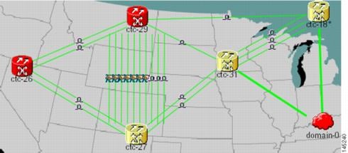 The following figure shows a network view with globally consolidated links. 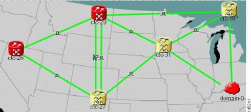 The following figure shows a network view with local DCC link consolidation between two nodes. 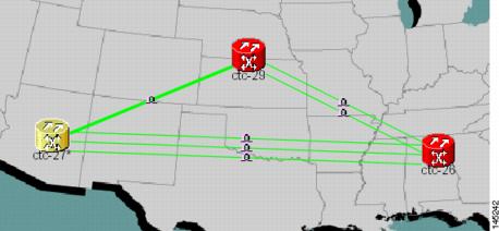 |
|
Step 6 |
To view information about a consolidated link, either move your mouse over the link (the tooltip displays the number of links and the link class) or single-click the link to display detailed information on the left side of the window. |
|
Step 7 |
To access an individual link within a consolidated link (for example, if you need to perform a span upgrades):
|
|
Step 8 |
To expand locally consolidated links, right-click the consolidated link and choose Expand [link class] Links from the shortcut menu, where "link class" is DCC, PPC, etc. |
|
Step 9 |
To filter the links by class: |
|
Step 10 |
Return to your originating procedure (NTP). |
NTP-G83 Modify or Delete Card Protection Settings
|
Purpose |
This procedure modifies and deletes card protection settings. |
|
Tools/Equipment |
None |
|
Prerequisite Procedures |
|
|
Required/As Needed |
As needed |
|
Onsite/Remote |
Onsite or remote |
|
Security Level |
Provisioning or higher |
Caution |
Modifying and deleting protection groups can be service affecting. |
Procedure
|
Step 1 |
Perform any of the following tasks as needed: |
|
Step 2 |
Complete the "NTP-G103 Back Up the Database" procedure in the chapter, "Maintain the Node" of the Cisco ONS 15454 DWDM Configuration Guide. Stop. You have completed this procedure. |
DLP-G175 Modify a Y-Cable Protection Group
|
Purpose |
This task modifies a Y-cable protection group that has been created for two TXP, MXP, GE_XP, 10GE_XP, GE_XPE, 10GE_XPE, or OTU2_XP card client ports. |
|
Tools/Equipment |
None |
|
Prerequisite Procedures |
"DLP-G46 Log into CTC" task in the "Connect the PC and Log into the GUI" document. NTP-G33 Create a Y-Cable Protection Group. Refer the chapter, "Provision Transponder and Muxponder Cards" in the Cisco ONS 15454 DWDM Configuration Guide. |
|
Required/As Needed |
As needed |
|
Onsite/Remote |
Onsite or remote |
|
Security Level |
Provisioning or higher |
Procedure
|
Step 1 |
In node view (single-shelf mode) or shelf view (multishelf mode), click the Provisioning > Protection tabs. |
|
Step 2 |
In the Protection Groups area, click the Y-cable protection group that you want to modify. |
|
Step 3 |
Click Edit. |
|
Step 4 |
In the Selected Group area, you can modify the following, as needed:
|
|
Step 5 |
Click OK. Confirm that the changes appear. |
|
Step 6 |
Return to your originating procedure (NTP). |
DLP-G176 Modify a Splitter Protection Group
|
Purpose |
This task modifies a splitter protection group that has been created on a TXPP_MR_2.5G, MXPP_MR_2.5G, PSM, or OTU2_XP card. Splitter protection is automatically created when the TXPP_MR_2.5G, MXPP_MR_2.5G, or PSM card is installed. For the OTU2_XP card, a splitter protection group is configurable and can be created on Ports 3 and 4 . |
|
Tools/Equipment |
None |
|
Prerequisite Procedures |
"DLP-G46 Log into CTC" task in the "Connect the PC and Log into the GUI" document. |
|
Required/As Needed |
As needed |
|
Onsite/Remote |
Onsite or remote |
|
Security Level |
Provisioning or higher |
Procedure
|
Step 1 |
In node view (single-shelf mode) or shelf view (multishelf mode), click the Provisioning > Protection tabs. |
||
|
Step 2 |
In the Protection Groups area, click the splitter protection group that you want to modify. |
||
|
Step 3 |
Click Edit. |
||
|
Step 4 |
In the Selected Group area, you can modify the following, as needed:
|
||
|
Step 5 |
Click OK. Confirm that the changes appear. |
||
|
Step 6 |
Return to your originating procedure (NTP). |
DLP-G177 Delete a Y-Cable Protection Group
|
Purpose |
This task deletes a Y-cable protection group. |
|
Tools/Equipment |
None |
|
Prerequisite Procedures |
"DLP-G46 Log into CTC" task in the "Connect the PC and Log into the GUI" document. |
|
Required/As Needed |
As needed |
|
Onsite/Remote |
Onsite or remote |
|
Security Level |
Provisioning or higher |
Procedure
|
Step 1 |
In node view (single-shelf mode) or shelf view (multishelf mode), double-click the near end transponder card to open it in the card view. |
||
|
Step 2 |
In the card view mode, click the Provisioning tab. The Line tab view with the ports provisioned is displayed. |
||
|
Step 3 |
Click the Admin State list box and select the Out-of-Service (OOS) option for the near end transponder trunk and client ports (for example, "1-1(OC3), 2(OC48)"). |
||
|
Step 4 |
Click Apply. Repeat above two steps for the far end transponder card. |
||
|
Step 5 |
Right-click the transponder card in card view mode and select Go to Parent View. |
||
|
Step 6 |
In node view (single-shelf mode) or shelf view (multishelf mode), click the Provisioning > Protection tabs. |
||
|
Step 7 |
In the Protection Groups area, disconnect the Y-cable fiber for the protection transponder ports in the protection group you want to delete. |
||
|
Step 8 |
Select the protection group and click Delete. |
||
|
Step 9 |
Click Yes in the Delete Protection Group dialog box. Confirm that the changes appear. |
||
|
Step 10 |
Return to your originating procedure (NTP).
|
DLP-G459 Delete a Splitter Protection Group
|
Purpose |
This task deletes a splitter protection group on the OTU2_XP card. For the TXPP_MR_2.5G or MXPP_MR_2.5G card, the splitter protection group is deleted when you delete the card. |
|
Tools/Equipment |
None |
|
Prerequisite Procedures |
"DLP-G46 Log into CTC" task in the "Connect the PC and Log into the GUI" document. |
|
Required/As Needed |
As needed |
|
Onsite/Remote |
Onsite or remote |
|
Security Level |
Provisioning or higher |
Procedure
|
Step 1 |
In node view (single-shelf mode) or shelf view (multishelf mode), click the Provisioning > Protection tabs. |
|
Step 2 |
In the Protection Groups area, click the protection group you want to delete. |
|
Step 3 |
Click Delete. |
|
Step 4 |
Click Yes in the Delete Protection Group dialog box. Confirm that the changes appear. |
|
Step 5 |
Return to your originating procedure (NTP). |
NTP-G84 Initiate and Clear Y-Cable and Splitter External Switching Commands
|
Purpose |
This procedure describes how to apply and remove Manual and Force protection switches on Y-cable and splitter protection groups. It also describes how to apply and remove a Lock On or Lock Out protection command to a Y-cable protection group. |
|
Tools/Equipment |
None |
|
Prerequisite Procedures |
"DLP-G46 Log into CTC" task in the "Connect the PC and Log into the GUI" document. In the Cisco ONS 15454 DWDM Configuration Guide:
|
|
Required/As Needed |
As needed |
|
Onsite/Remote |
Onsite or remote |
|
Security Level |
Superuser only |
Procedure
|
Step 1 |
To perform a Manual protection switch, complete the DLP-G178 Apply a Manual Y-Cable or Splitter Protection Switch. |
|
Step 2 |
To perform a Force protection switch, complete the DLP-G179 Apply a Force Y-Cable or Splitter Protection Switch. |
|
Step 3 |
To clear a Force or Manual protection switch, complete the DLP-G180 Clear a Manual or Force Y-Cable or Splitter Protection Switch. |
|
Step 4 |
To prevent traffic on a working or protect card from switching to the other card in the pair, complete the DLP-G181 Apply a Lock-On. |
|
Step 5 |
To prevent traffic from switching to the protect card, complete the DLP-G182 Apply a Lockout. |
|
Step 6 |
To remove a lock-on or lockout and return a protection group to its usual switching method, complete the DLP-G183 Clear a Lock-On or Lockout. Stop. You have completed this procedure. |
DLP-G178 Apply a Manual Y-Cable or Splitter Protection Switch
|
Purpose |
This task performs a Manual protection switch on a Y-cable or splitter protection group. |
|
Tools/Equipment |
None |
|
Prerequisite Procedures |
"DLP-G46 Log into CTC" task in the "Connect the PC and Log into the GUI" document. |
|
Required/As Needed |
As needed |
|
Onsite/Remote |
Onsite or remote |
|
Security Level |
Maintenance or higher |
Caution |
A Manual switch will move traffic from the active to the standby card only if network conditions permit it. If conditions change during the switch, CTC will attempt to place traffic back on the original active card. |
Procedure
|
Step 1 |
In node view (single-shelf mode) or shelf view (multishelf mode), click the Maintenance > Protection tabs. |
|
Step 2 |
In the Protection Groups list, click the Y-cable or splitter protection group where you want to apply the Manual protection switch. |
|
Step 3 |
In the Selected Group area, click the active card or port . |
|
Step 4 |
In the Switch Commands drop-down list, click Manual. |
|
Step 5 |
In the Confirm Manual Operation dialog box, click Yes. If conditions permit, the Manual switch will be applied. To clear the Manual switch, see the DLP-G180 Clear a Manual or Force Y-Cable or Splitter Protection Switch. |
|
Step 6 |
Return to your originating procedure (NTP). |
DLP-G179 Apply a Force Y-Cable or Splitter Protection Switch
|
Purpose |
This task performs a Force protection switch on a Y-cable or splitter protection group. |
|
Tools/Equipment |
None |
|
Prerequisite Procedures |
"DLP-G46 Log into CTC" task in the "Connect the PC and Log into the GUI" document. |
|
Required/As Needed |
As needed |
|
Onsite/Remote |
Onsite or remote |
|
Security Level |
Maintenance or higher |
Caution |
A Force switch will move traffic from the active to the standby card or port immediately, regardless of network conditions. The switch will remain in effect until it is cleared. |
Procedure
|
Step 1 |
In node view (single-shelf mode) or shelf view (multishelf mode), click the Maintenance > Protection tabs. |
|
Step 2 |
In the Protection Groups list, click the Y-cable or splitter protection group where you want to apply the Force protection switch. |
|
Step 3 |
In the Selected Group area, click the active card or port. |
|
Step 4 |
In the Switch Commands drop-down list, click Force. |
|
Step 5 |
In the Confirm Manual Operation dialog box, click Yes. The Force switch will be applied. To clear the Force switch, see the DLP-G180 Clear a Manual or Force Y-Cable or Splitter Protection Switch. |
|
Step 6 |
Return to your originating procedure (NTP). |
DLP-G180 Clear a Manual or Force Y-Cable or Splitter Protection Switch
|
Purpose |
This task clears a Manual or Force protection switch on a Y-cable or splitter protection group. |
|
Tools/Equipment |
None |
|
Prerequisite Procedures |
|
|
Required/As Needed |
As needed |
|
Onsite/Remote |
Onsite or remote |
|
Security Level |
Maintenance or higher |
Procedure
|
Step 1 |
In node view (single-shelf mode) or shelf view (multishelf mode), click the Maintenance > Protection tabs. |
|
Step 2 |
In the Protection Groups area, click the protection group that contains the card you want to clear. |
|
Step 3 |
In the Selected Group area, click the card that you want to clear. |
|
Step 4 |
In the Switch Commands drop-down list, click Clear. |
|
Step 5 |
Click Yes in the confirmation dialog box. The Manual or Force protection switch is cleared. |
|
Step 6 |
Return to your originating procedure (NTP). |
DLP-G181 Apply a Lock-On
|
Purpose |
This task prevents traffic from being switched from the working/active card in a Y-cable protection group or port in a splitter protection group. |
|
Tools/Equipment |
None |
|
Prerequisite Procedures |
"DLP-G46 Log into CTC" task in the "Connect the PC and Log into the GUI" document. |
|
Required/As Needed |
As needed |
|
Onsite/Remote |
Onsite or remote |
|
Security Level |
Maintenance or higher |
Caution |
You can apply the Lock On command only to the working/active card or port. If the working card or port is standby (traffic is switched), the Lock On button is not available. |
Procedure
|
Step 1 |
In node view (single-shelf mode) or shelf view (multishelf mode), click the Maintenance > Protection tabs. |
||
|
Step 2 |
In the Protection Groups area, click the protection group that contains the card (Y-cable) or port (splitter) that you want to lock on. |
||
|
Step 3 |
In the Selected Group area, click the working/active card. |
||
|
Step 4 |
In the Inhibit Switching drop-down list, click Lock On. |
||
|
Step 5 |
Click Yes in the confirmation dialog box. The lock-on has been applied. Traffic cannot switch to the protect card. To clear the lock-on, see the DLP-G183 Clear a Lock-On or Lockout.
|
||
|
Step 6 |
Return to your originating procedure (NTP). |
DLP-G182 Apply a Lockout
|
Purpose |
This task keeps traffic from switching to the protect/standby card or port. The Lock Out command overrides the Force and Manual switching commands. |
|
Tools/Equipment |
None |
|
Prerequisite Procedures |
"DLP-G46 Log into CTC" task in the "Connect the PC and Log into the GUI" document. |
|
Required/As Needed |
As needed |
|
Onsite/Remote |
Onsite or remote |
|
Security Level |
Maintenance or higher |
Note |
You can apply the lockout to the protect/standby card or port. If the protect card or port is active (traffic is switched), the lockout task cannot be performed. |
Procedure
|
Step 1 |
In node view (single-shelf mode) or shelf view (multishelf mode), click the Maintenance > Protection tabs. |
||
|
Step 2 |
In the Protection Groups area, click the protection group that contains the card (Y-cable) or port (splitter) that you want to lock out. |
||
|
Step 3 |
In the Selected Group area, click the protect/standby card. |
||
|
Step 4 |
In the Inhibit Switching drop-down list, click Lock Out. |
||
|
Step 5 |
Click Yes in the confirmation dialog box. The lockout has been applied. Traffic cannot switch to the protect card. To clear the lockout, see the DLP-G183 Clear a Lock-On or Lockout.
|
||
|
Step 6 |
Return to your originating procedure (NTP). |
DLP-G183 Clear a Lock-On or Lockout
|
Purpose |
This task clears a lock-on or lockout. |
|
Tools/Equipment |
None |
|
Prerequisite Procedures |
|
|
Required/As Needed |
As needed |
|
Onsite/Remote |
Onsite or remote |
|
Security Level |
Maintenance or higher |
Procedure
|
Step 1 |
In node view (single-shelf mode) or shelf view (multishelf mode), click the Maintenance > Protection tabs. |
|
Step 2 |
In the Protection Groups area, click the protection group that contains the card you want to clear. |
|
Step 3 |
In the Selected Group area, click the card you want to clear. |
|
Step 4 |
In the Inhibit Switching drop-down list, click Unlock. |
|
Step 5 |
Click Yes in the confirmation dialog box. The lock-on or lockout is cleared. |
|
Step 6 |
Return to your originating procedure (NTP). |
NTP-G85 Modify or Delete OSC Terminations, DCC/GCC Terminations, and Provisionable Patchcords
|
Purpose |
This procedure modifies DCC/GCC terminations, and deletes provisionable patchcords, OSC terminations, and DCC/GCC terminations. |
|
Tools/Equipment |
None |
|
Prerequisite Procedures |
"DLP-G46 Log into CTC" task in the "Connect the PC and Log into the GUI" document. One or more of the following tasks in the in the Cisco ONS 15454 DWDM Configuration Guide:
|
|
Required/As Needed |
As needed |
|
Onsite/Remote |
Onsite or remote |
|
Security Level |
Provisioning or higher |
Procedure
|
In node view (single-shelf mode) or multishelf view (multishelf mode), complete the following tasks as needed: Stop. You have completed this procedure. |
DLP-G184 Change a DCC/GCC Termination
|
Purpose |
This task modifies a DCC/GCC termination. You can enable or disable OSPF and enable or disable the foreign node setting. |
|
Tools/Equipment |
None |
|
Prerequisite Procedures |
"DLP-G46 Log into CTC" task in the "Connect the PC and Log into the GUI" document. |
|
Required/As Needed |
As needed |
|
Onsite/Remote |
Onsite or remote |
|
Security Level |
Provisioning or higher |
Procedure
|
Step 1 |
In node view (single-shelf mode) or shelf view (multishelf mode), click the Provisioning > Comm Channels. |
|
Step 2 |
Select the DCC or GCC tabs as necessary. Available tabs are:
|
|
Step 3 |
Select the DCC/GCC that you want to change. |
|
Step 4 |
Click Edit. The Edit Termination dialog box appears |
|
Step 5 |
Complete the following as necessary:
|
|
Step 6 |
Click OK. |
|
Step 7 |
Return to your origination procedure (NTP). |
DLP-G185 Delete a DCC/GCC Termination
|
Purpose |
This task deletes the DWDM DCC/GCC terminations required for network setup when using TXP, MXP, or XP cards. |
|
Tools/Equipment |
None |
|
Prerequisite Procedures |
"DLP-G46 Log into CTC" task in the "Connect the PC and Log into the GUI" document. |
|
Required/As Needed |
As needed |
|
Onsite/Remote |
Onsite or remote |
|
Security Level |
Provisioning or higher |
Note |
Deleting the DCC/GCC termination on a port also deletes any provisionable patchcord links that might exist on the port. |
Procedure
|
Step 1 |
In node view (single-shelf mode) or shelf view (multishelf mode), click the Provisioning > Comm Channels. |
|
Step 2 |
Select the DCC or GCC tabs as necessary. Available tabs are:
|
|
Step 3 |
Select the DCC/GCC that you want to delete. |
|
Step 4 |
Click Delete. |
|
Step 5 |
In the Delete Terminations dialog box, check the Set port OOS check box if you want to place ports out of service. |
|
Step 6 |
Click Yes. The following alarms will appear until all network terminations are deleted and the ports are out of service:
|
|
Step 7 |
Return to your originating procedure (NTP). |
DLP-G186 Delete an OSC Termination
|
Purpose |
This task deletes an OSC termination on the ONS 15454 node. |
|
Tools/Equipment |
None |
|
Prerequisite Procedures |
"DLP-G46 Log into CTC" task in the "Connect the PC and Log into the GUI" document. |
|
Required/As Needed |
As needed |
|
Onsite/Remote |
Onsite or remote |
|
Security Level |
Provisioning or higher |
Caution |
Deleting an OSC termination might cause node isolation and loss of visibility to nodes that do not have other OSCs or network connections to the CTC computer. |
Note |
To delete OSC on a TNC or TNCE port, UDC/VoIP configuration must be set to None . |
Procedure
|
Step 1 |
In node view (single-shelf mode) or shelf view (multishelf mode), click the Provisioning > Comm Channels > OSC tab. |
|
Step 2 |
Click the OSC termination that you want to delete and click Delete. |
|
Step 3 |
In the Delete OSC Termination confirmation box, click Yes. Confirm that the changes appear. Until all network OSC terminations are deleted, loss of signal (LOS) or power failure alarms might appear on the OPT-BST amplifier, OSCM card, and OSC-CSM card. |
|
Step 4 |
Return to your originating procedure (NTP). |
DLP-G187 Delete a Provisionable Patchcord
|
Purpose |
This task deletes a provisionable patchcord. |
|
Tools/Equipment |
None |
|
Prerequisite Procedures |
"DLP-G46 Log into CTC" task in the "Connect the PC and Log into the GUI" document. |
|
Required/As Needed |
As needed |
|
Onsite/Remote |
Onsite or remote |
|
Security Level |
Provisioning or higher |
Procedure
|
Step 1 |
In node view (single-shelf mode) or multishelf view (multishelf mode), click the Provisioning > Comm Channels > PPC tab. If you are in network view, click the Provisioning > Provisionable Patchcords tab. |
|
Step 2 |
Click the provisionable patchcord that you want to delete. |
|
Step 3 |
Click Delete. |
|
Step 4 |
In the confirmation dialog box, click Yes. |
|
Step 5 |
Return to your originating procedure (NTP). |
NTP-G86 Convert a Pass-Through Connection to Add/Drop Connections
|
Purpose |
This procedure converts a pass-through connection into add/drop connections (one on the add side and the other on the drop side). Use this procedure during a network upgrade. Pass-through channel connections can be provided between channel input and output ports for the AD-xC-xx.x, 4MD-xx.x, 32MUX-O, 32DMX-O, 32DMX, 32DMX-L, 40-MUX-C, and 40-DMX-C/40-DMX-CE cards. You can set up pass-through connections in nodes that might require more add or drop channel capability or configuration. |
|
Tools/Equipment |
None |
|
Prerequisite Procedures |
"DLP-G46 Log into CTC" task in the "Connect the PC and Log into the GUI" document. |
|
Required/As Needed |
As needed |
|
Onsite/Remote |
Onsite or remote |
|
Security Level |
Provisioning or higher |
Procedure
|
Step 1 |
In node view (single-shelf mode) or multishelf view (multishelf mode), click the Circuits tab. Delete the unidirectional or bidirectional pass-through optical channel network connection (OCHNC) that applies to the pass-through connection to be removed. |
||
|
Step 2 |
Remove the physical pass-through cabling. Click the Provisioning > WDM-ANS > Internal Patchcords tabs to identify the card ports to be removed. The pass-through connection that you are removing can be connected in both OADM and hub nodes.
|
||
|
Step 3 |
Physically connect the proper client interface to the correct add and drop ports. |
||
|
Step 4 |
Delete the filter connections related to the pass-through connection that is being converted to an add/drop connection:
|
||
|
Step 5 |
Create two new unidirectional OCHNCs (one heading Side B, the other heading Side A) to support the new add/drop channels. See the "DLP-G105 Provision Optical Channel Network Connections" task in the chapter, "Create Optical Channel Circuits and Provisionable Patchcords" of the Cisco ONS 15454 DWDM Configuration Guide. |
||
|
Step 6 |
As necessary, complete the "NTP-G184 Create a Provisionable Patchcord" procedure in the chapter, "Create Optical Channel Circuits and Provisionable Patchcords" in the Cisco ONS 15454 DWDM Configuration Guide. |
||
|
Step 7 |
As necessary, add an optical attenuator between the channel TX port of the AD-xC-xx.x, 4MD-xx.x, 32DMX-O, 32DMX, 32-DMX-L, or 40-DMX-C/40-DMX-CE card and the DWDM RX port on the TXP, MXP, or OC-N/STM-N ITU-T line card.
|
||
|
Step 8 |
(Optional) The following verification steps might be needed for an intermediate node when a pass-through connection is converted: |
NTP-G87 Change Node Timing Parameters
|
Purpose |
This procedure changes the timing parameters for the ONS 15454. To switch the timing reference, see the "NTP-G112 Change the Node Timing Reference" procedure in the chapter "Maintain the Node" of the Cisco ONS 15454 DWDM Configuration Guide. |
|
Tools/Equipment |
None |
|
Prerequisite Procedures |
DLP-G46 Log into CTC" task in the "Connect the PC and Log into the GUI" document. NTP-G53 Set Up Timing. Refer the chapter, "Turn Up a Network" in the Cisco ONS 15454 DWDM Configuration Guide. |
|
Required/As Needed |
As needed |
|
Onsite/Remote |
Onsite or remote |
|
Security Level |
Provisioning or higher |
Caution |
The following procedure might be service affecting and should be performed during a scheduled maintenance window. |
Procedure
|
Step 1 |
Complete the "NTP-G103 Back Up the Database" procedure in the chapter, "Maintain the Node" of the Cisco ONS 15454 DWDM Configuration Guide. |
||
|
Step 2 |
Click the Provisioning > Timing > General tabs. |
||
|
Step 3 |
In the General Timing section, change any of the following information:
See the "NTP-G53 Set Up Timing" task in the chapter, "Turn Up Network" of the Cisco ONS 15454 DWDM Configuration Guide field descriptions. |
||
|
Step 4 |
In the Reference Lists area, you can change the following information:
|
||
|
Step 5 |
In node view (single-shelf mode) or shelf view (multishelf mode), click the Provisioning > Timing > BITS Facilities tabs. |
||
|
Step 6 |
In the BITS In section, you can change the following information:
|
||
|
Step 7 |
In the BITS Out section, you can change the following information:
|
||
|
Step 8 |
Click Apply. Confirm that the changes appear. Stop. You have completed this procedure. |
NTP-G88 Modify Users and Change Security
|
Purpose |
This procedure modifies user and security properties for the ONS 15454. |
|
Tools/Equipment |
None |
|
Prerequisite Procedures |
|
|
Required/As Needed |
As needed |
|
Onsite/Remote |
Onsite or remote |
|
Security Level |
Superuser only |
Procedure
|
Step 1 |
Complete the "NTP-G103 Back Up the Database" procedure in the chapter, "Maintain the Node" of the Cisco ONS 15454 DWDM Configuration Guide. |
|
Step 2 |
Perform any of the following tasks as needed: |
|
Step 3 |
Complete the "NTP-G103 Back Up the Database" procedure in the chapter, "Maintain the Node" of the Cisco ONS 15454 DWDM Configuration Guide. Stop. You have completed this procedure. |
DLP-G188 Change Security Policy for a Single Node
|
Purpose |
This task changes the security policy for a single node, including idle user timeouts, user lockouts, password changes, and concurrent login policies. |
|
Tools/Equipment |
None |
|
Prerequisite Procedures |
"DLP-G46 Log into CTC" task in the "Connect the PC and Log into the GUI" document. |
|
Required/As Needed |
As needed |
|
Onsite/Remote |
Onsite or remote |
|
Security Level |
Superuser or Security super user |
Procedure
|
Step 1 |
In node view (single-shelf mode) or multishelf view (multishelf mode), click the Provisioning > Security > Policy tabs. |
||
|
Step 2 |
If you want to modify the idle user timeout period, click the hour (H) and minute (M) arrows in the Idle User Timeout area for the security level that you want to provision: RETRIEVE, MAINTENANCE, PROVISIONING, SUPERUSER, SECURITY USER, SECURITY SUPER USER, or ROOT15 USER. The idle period time range is 0 and 16 hours, and 0 and 59 minutes. The user is logged out after the idle user timeout period is reached. |
||
|
Step 3 |
In the User Lockout area, you can modify the following:
|
||
|
Step 4 |
In the Password Change area, you can modify the following:
|
||
|
Step 5 |
To require users to change their password at periodic intervals, check the Enforce Password Aging check box in the Password Aging area. If checked, provision the following parameters:
|
||
|
Step 6 |
In the Other area, you can provision the following:
|
||
|
Step 7 |
Click Apply. Confirm that the changes appear. |
||
|
Step 8 |
Return to your originating procedure (NTP). |
DLP-G189 Change Security Policy for Multiple Nodes
|
Purpose |
This task changes the security policy for multiple nodes including idle user timeouts, user lockouts, password changes, and concurrent login policies. |
|
Tools/Equipment |
None |
|
Prerequisite Procedures |
"DLP-G46 Log into CTC" task in the "Connect the PC and Log into the GUI" document. |
|
Required/As Needed |
As needed |
|
Onsite/Remote |
Onsite or remote |
|
Security Level |
Superuser or Security super user |
Procedure
|
Step 1 |
From the View menu, choose Go to Network View. |
||
|
Step 2 |
Click the Provisioning > Security > Policy tabs. A read-only table of nodes and their policies appears. |
||
|
Step 3 |
Click a node on the table that you want to modify, then click Change. |
||
|
Step 4 |
If you want to modify the idle user timeout period, click the hour (H) and minute (M) arrows in the Idle User Timeout area for the security level that you want to provision: RETRIEVE, MAINTENANCE, PROVISIONING, SUPERUSER, SECURITY USER, SECURITY SUPER USER, or ROOT15 USER. The idle period time range is 0 and 16 hours, and 0 and 59 minutes. The user is logged out after the idle user timeout period is reached. |
||
|
Step 5 |
In the User Lockout area, you can modify the following:
|
||
|
Step 6 |
In the Password Change area, you can modify the following:
|
||
|
Step 7 |
To require users to change their password at periodic intervals, check the Enforce Password Aging check box in the Password Aging area. If checked, provision the following parameters:
|
||
|
Step 8 |
In the Other area, you can provision the following:
|
||
|
Step 9 |
In the Select Applicable Nodes area, uncheck any nodes where you do not want to apply the changes. |
||
|
Step 10 |
Click OK. |
||
|
Step 11 |
In the Security Policy Change Results dialog box, confirm that the changes are correct, then click OK. |
||
|
Step 12 |
Return to your originating procedure (NTP). |
DLP-G317 Change Node Access and PM Clearing Privilege
|
Purpose |
This task provisions the physical access points and shell programs used to connect to the ONS 15454 and sets the user security level that can clear node performance monitoring (PM) data. |
|
Tools/Equipment |
None |
|
Prerequisite Procedures |
"DLP-G46 Log into CTC" task in the "Connect the PC and Log into the GUI" document. |
|
Required/As Needed |
As needed |
|
Onsite/Remote |
Onsite or remote |
|
Security Level |
Superuser only |
Procedure
|
Step 1 |
In node view (single-shelf mode) or multishelf view (multishelf mode), click the Provisioning > Security > Access tabs. |
|
Step 2 |
In the Access area, provision the following:
|
|
Step 3 |
In the Shell Access area, set the shell program used to access the node:
|
|
Step 4 |
In the TL1 Access area, select the desired level of TL1 access. Disabled completely disables all TL1 access; Non-Secure and Secure allow access using SSH. |
|
Step 5 |
In the PM Clearing Privilege field, choose the minimum security level that can clear node PM data: PROVISIONING or SUPERUSER. |
|
Step 6 |
Check the Enable Craft Port check box to turn on the shelf controller serial ports. |
|
Step 7 |
Select the EMS access state from the list. Available states are Non-Secure and Secure (allows access using SSH). |
|
Step 8 |
In the TCC CORBA (IIOP/SSLIOP) Listener Port area, choose a listener port option:
|
|
Step 9 |
In the SNMP Access area, set the Simple Network Management Protocol (SNMP) access state to Non-Secure or Disabled (disables SNMP access). |
|
Step 10 |
Click Apply. |
|
Step 11 |
Return to your originating procedure (NTP). |
DLP-G328 Grant Superuser Privileges to a Provisioning User
|
Purpose |
This task enables a provisioning user to retrieve audit logs, restore databases, clear PMs, and activate and revert software loads. |
|
Tools/Equipment |
None |
|
Prerequisite Procedures |
"DLP-G46 Log into CTC" task in the "Connect the PC and Log into the GUI" document. |
|
Required/As Needed |
As needed |
|
Onsite/Remote |
Onsite or remote |
|
Security Level |
Superuser only |
Procedure
|
Step 1 |
In node view (single-shelf mode) or multishelf view (multishelf mode), click the Provisioning > Defaults tabs. |
|
Step 2 |
In the Defaults Selector area, choose NODE. |
|
Step 3 |
In the Default Name area, choose one of the following parameters:
|
|
Step 4 |
Click the Default Value column and choose Provisioning from the drop-down list for each property listed in the previous step, that you want to change. |
|
Step 5 |
Click Apply. A pencil icon will appear next to the default name that will be changed as a result of editing the defaults file. |
|
Step 6 |
Return to your originating procedure (NTP). |
DLP-G191 Change User Password and Security Level on a Single Node
|
Purpose |
This task changes settings for an existing user at one node. |
|
Tools/Equipment |
None |
|
Prerequisite Procedures |
"DLP-G46 Log into CTC" task in the "" document. |
|
Required/As Needed |
As needed |
|
Onsite/Remote |
Onsite or remote |
|
Security Level |
Superuser only |
Note |
Each ONS 15454 must have one user with a Superuser security level. The default CISCO15 user name and security level cannot be changed unless you create another user with Superuser security. |
Procedure
|
Step 1 |
In node view (single-shelf mode) or multishelf view (multishelf mode), click the Provisioning > Security > Users tabs. |
||
|
Step 2 |
Click the user whose settings you want to modify, then click Edit. |
||
|
Step 3 |
In the Change User dialog box, you can:
See the "DLP-G54 Create a New User on a Single Node" task in the chapter, "Turn Up a Node" of the Cisco ONS 15454 DWDM Configuration Guide. |
||
|
Step 4 |
Click OK. |
||
|
Step 5 |
Click OK in the confirmation dialog box.
|
||
|
Step 6 |
Return to your originating procedure (NTP). |
DLP-G192 Change User Password and Security Level for Multiple Nodes
|
Purpose |
This task changes settings for an existing user at multiple nodes. |
|
Tools/Equipment |
None |
|
Prerequisite Procedures |
"DLP-G46 Log into CTC" task in the "Connect the PC and Log into the GUI" document. |
|
Required/As Needed |
As needed |
|
Onsite/Remote |
Onsite or remote |
|
Security Level |
Superuser only |
Procedure
|
Step 1 |
From the View menu, choose Go to Network View. Verify that you can access all the nodes where you want to change the users. |
||
|
Step 2 |
Click the Provisioning > Security > Users tabs. Highlight the user's name whose settings you want to change. |
||
|
Step 3 |
Click Change. The Change User dialog box appears. |
||
|
Step 4 |
In the Change User dialog box, you can:
See the "DLP-G54 Create a New User on a Single Node" task in the chapter, "Turn Up a Node" of the Cisco ONS 15454 DWDM Configuration Guide. |
||
|
Step 5 |
In the Select Applicable Nodes area, uncheck any nodes where you do not want to change the user's settings (all network nodes are selected by default).
|
||
|
Step 6 |
Click OK. A Change Results confirmation dialog box appears. |
||
|
Step 7 |
Click OK to acknowledge the changes. |
||
|
Step 8 |
Return to your originating procedure (NTP). |
DLP-G193 Delete a User From a Single Node
|
Purpose |
This task deletes an existing user from a single node. |
|
Tools/Equipment |
None |
|
Prerequisite Procedures |
"DLP-G46 Log into CTC" task in the "Connect the PC and Log into the GUI" document. |
|
Required/As Needed |
As needed |
|
Onsite/Remote |
Onsite or remote |
|
Security Level |
Superuser only |
Note |
You cannot delete a user who is currently logged in. To log out a user, you can complete the "DLP-G195 Log Out a User on a Single Node" task, or you can choose the "Logout before delete" option in the Delete User dialog box. |
Note |
CTC will allow you to delete other Superusers if one Superuser remains. For example, you can delete the CISCO15 user if you have created another Superuser. Use this option with caution. |
Procedure
|
Step 1 |
In node view (single-shelf mode) or multishelf view (multishelf mode), click the Provisioning > Security > Users tabs. |
|
Step 2 |
Choose the user that you want to delete. |
|
Step 3 |
Click Delete. |
|
Step 4 |
In the Delete User dialog box, verify that the user name displayed is the one that you want to delete. Check the Logout before delete checkbox if the user is currently logged in. (You cannot delete users if they are logged in.) When theLogout before delete checkbox is checked, the DISCONNECTED alarm is raised. |
|
Step 5 |
Click OK. |
|
Step 6 |
In the User Deletion Results box, click OK. |
|
Step 7 |
Return to your originating procedure (NTP). |
DLP-G194 Delete a User From Multiple Nodes
|
Purpose |
This task deletes an existing user from multiple nodes. |
|
Tools/Equipment |
None |
|
Prerequisite Procedures |
"DLP-G46 Log into CTC" task in the "Connect the PC and Log into the GUI" document. |
|
Required/As Needed |
As needed |
|
Onsite/Remote |
Onsite or remote |
|
Security Level |
Superuser only |
Note |
You cannot delete a user who is currently logged in. To log out a user, you can complete the "DLP-G195 Log Out a User on a Single Node" task, or you can choose the "Logout before delete" option in the Delete User dialog box. |
Note |
CTC will allow you to delete other Superusers if one Superuser remains. For example, you can delete the CISCO15 user if you have created another Superuser. Use this option with caution. |
Procedure
|
Step 1 |
From the View menu, choose Go to Network View. |
||
|
Step 2 |
Click the Provisioning > Security tabs. Highlight the name of the user you want to delete. |
||
|
Step 3 |
Click Delete. The Delete User dialog box appears. |
||
|
Step 4 |
In the Select Applicable Nodes area, uncheck any nodes where you do not want to delete this user.
|
||
|
Step 5 |
Click OK. A User Deletion Results confirmation dialog box appears. |
||
|
Step 6 |
Click OK to acknowledge the changes. |
||
|
Step 7 |
Return to your originating procedure (NTP). |
DLP-G195 Log Out a User on a Single Node
|
Purpose |
This task logs out a user from a single node. |
|
Tools/Equipment |
None |
|
Prerequisite Procedures |
"DLP-G46 Log into CTC" task in the "Connect the PC and Log into the GUI" document. |
|
Required/As Needed |
As needed |
|
Onsite/Remote |
Onsite or remote |
|
Security Level |
Superuser only |
Procedure
|
Step 1 |
In node view (single-shelf mode) or multishelf view (multishelf mode), click the Provisioning > Security > Active Logins tabs. |
|
Step 2 |
Choose the user that you want to log out and click Logout. |
|
Step 3 |
In the Logout User dialog box, check Lockout before Logout if you want to lock the user out. This prevents the user from logging in after logout based on user lockout parameters provisioned in the Policy tab. A manual unlock by a Superuser is required, or else the user is locked out for the amount of time specified in the Lockout Duration field. See the "DLP-G188 Change Security Policy for a Single Node" task for more information. |
|
Step 4 |
Click OK. |
|
Step 5 |
Click OK to confirm the logout. |
|
Step 6 |
Return to your originating procedure (NTP). |
DLP-G196 Log Out a User on Multiple Nodes
|
Purpose |
This task logs out a user from multiple nodes. |
|
Tools/Equipment |
None |
|
Prerequisite Procedures |
"DLP-G46 Log into CTC" task in the "Connect the PC and Log into the GUI" document. |
|
Required/As Needed |
As needed |
|
Onsite/Remote |
Onsite or remote |
|
Security Level |
Superuser only |
Procedure
|
Step 1 |
From the View menu, choose Go to Network View. |
|
Step 2 |
Click the Provisioning > Security > Active Logins tabs. |
|
Step 3 |
Choose the user that you want to log out. |
|
Step 4 |
Click Logout. |
|
Step 5 |
In the Logout User dialog box, check the nodes where you want to log out the user. |
|
Step 6 |
Check the Lockout before Logout check box if you want to lock the user out prior to logout. This prevents the user from logging in after logout based on user lockout parameters provisioned in the Policy tab. A manual unlock by a Superuser is required, or else the user is locked out for the amount of time specified in the Lockout Duration field. See the "DLP-G189 Change Security Policy for Multiple Nodes" task for more information. |
|
Step 7 |
In the Select Applicable Nodes area, uncheck any nodes where you do not want to change the user's settings (all network nodes are selected by default). |
|
Step 8 |
Click OK. |
|
Step 9 |
Click OK in the confirmation dialog box. |
|
Step 10 |
Return to your originating procedure (NTP). |
DLP-G281 Configure the Node for RADIUS Authentication
|
Purpose |
This task allows you to configure a node for Remote Authentication Dial In User Service (RADIUS) authentication. RADIUS validates remote users who are attempting to connect to the network. |
|
Tools/Equipment |
None |
|
Prerequisite Procedures |
"DLP-G46 Log into CTC" task in the "Connect the PC and Log into the GUI" document. Before configuring the node for RADIUS authentication, you must first add the node as a network device on the RADIUS server. Refer to the User Guide for Cisco Secure ACS for Windows Server for more information about configuring a RADIUS server. |
|
Required/As Needed |
As needed |
|
Onsite/Remote |
Onsite or remote |
|
Security Level |
Superuser or Security super user |
Caution |
Do not configure a node for RADIUS authentication until after you have added that node to the RADIUS server and added the RADIUS server to the list of authenticators. If you do not add the node to a RADIUS server prior to activating RADIUS authentication, no user will be able to access the node. Refer to the User Guide for Cisco Secure ACS for Windows Server for more information about adding a node to a RADIUS server. |
Note |
The following Cisco vendor-specific attribute (VSA) needs to be specified when adding users to the RADIUS server: shell:priv-lvl=N where N is equal to:
|
Note |
|
Procedure
|
Step 1 |
In node view (single-shelf mode) or multishelf view (multishelf mode), click the Provisioning > Security > RADIUS Server tabs. |
||||
|
Step 2 |
Click Create to add a RADIUS server to the list of authenticators. The Create RADIUS Server Entry dialog box appears. |
||||
|
Step 3 |
Enter the RADIUS server IP address in the Node Address field. If the node is an end network element (ENE), enter the IP address of the gateway network element (GNE) in this field. The GNE passes authentication requests from the ENEs in its network to the RADIUS server, which grants authentication if the GNE is listed as a client on the server. The RADIUS port numbers used for the ENE RADIUS configuration map to the RADIUS configuration entries in the GNE. For example, the first RADIUS authentication port number configured in ENE (1860) maps to the first RADIUS authentication entry in the GNE. The port number 1863 maps to the fourth entry in the GNE and so on. The above logic applies to the configuration of the RADIUS accounting ports starting with port number 1870 for the first entry.
|
||||
|
Step 4 |
Enter the shared secret in the Shared Secret field. A shared secret is a masked text string that serves as a password between a RADIUS client and RADIUS server. |
||||
|
Step 5 |
Re-enter the shared secret in the Confirm Shared Secret field.
|
||||
|
Step 6 |
Enter the RADIUS authentication port number in the Authentication Port field. The default port is 1812. If the node is an ENE, set the authentication port to a number within the range of 1860 to 1869. |
||||
|
Step 7 |
Enter the RADIUS accounting port in the Accounting Port field. The default port is 1813. If the node is an ENE, set the accounting port to a number within the range of 1870 to 1879. |
||||
|
Step 8 |
Click OK. The RADIUS server details such as node address, authentication port, and accounting port is added to the list of RADIUS authenticators. The RADIUS authenticators list does not display shared secret since it is masked.
|
||||
|
Step 9 |
Click Edit to make changes to an existing RADIUS server. You can change the IP address, the shared secret, the authentication port, and the accounting port. |
||||
|
Step 10 |
Click Delete to delete the selected RADIUS server. |
||||
|
Step 11 |
Select a server and click Move Up or Move Down to reorder that server in the list of RADIUS authenticators. The node requests authentication from the servers sequentially from top to bottom. If one server is unreachable, the node will request authentication from the next RADIUS server on the list. |
||||
|
Step 12 |
Click the Enable RADIUS Authentication check box to activate remote-server authentication for the node. |
||||
|
Step 13 |
Click the Enable RADIUS Accounting check box if you want to show RADIUS authentication information in the audit trail. |
||||
|
Step 14 |
Click the Enable the Node as the Final Authenticator check box if you want the node to be the final authenticator. This means that if every RADIUS authenticator is unavailable, the node will authenticate the login rather than locking the user out. |
||||
|
Step 15 |
Click Apply to save all changes or Reset to clear all changes. |
||||
|
Step 16 |
Return to your originating procedure (NTP). |
DLP-G776 Configure the Node for TACACS+ Authentication
|
Purpose |
This task allows you to configure a node for Terminal Access Controller Access-Control System Plus (TACACS+) authentication. TACACS+ validates remote users who are attempting to connect to the network. |
|
Tools/Equipment |
None |
|
Prerequisite Procedures |
"DLP-G46 Log into CTC" task in the "Connect the PC and Log into the GUI" document. Before configuring the node for TACACS+ authentication, you must first add the node as a network device on the TACACS+ server. Refer to the Cisco IOS Security Configuration Guide for more information about configuring a TACACS+ server. |
|
Required/As Needed |
As needed |
|
Onsite/Remote |
Onsite or remote |
|
Security Level |
Superuser only |
Caution |
Do not configure a node for TACACS+ authentication until after you have added that node to the TACACS+ server and added the TACACS+ server to the list of authenticators. If you do not add the node to a TACACS+ server prior to activating TACACS+ authentication, no user will be able to access the node. |
Note |
The following Cisco vendor-specific attribute (VSA) needs to be specified when adding users to the TACACS+ server: shell:priv-lvl=N where N is equal to:
|
Procedure
|
Step 1 |
In node view (single-shelf mode) or multishelf view (multishelf mode), click the Provisioning > Security > TACACS Server tabs. |
||
|
Step 2 |
Click Create to add a TACACS server to the list of authenticators. The Create TACACS+ Server Entry dialog box appears. |
||
|
Step 3 |
Enter the IPv4 address of the TACACS+ server in the Node Address field. |
||
|
Step 4 |
Enter the shared secret in the Shared Secret field. A shared secret is a text string that serves as a password between a TACACS+ client and TACACS+ server. |
||
|
Step 5 |
Enter the TACACS+ authentication port number in the Authentication Port field. The default port is 49. |
||
|
Step 6 |
Click OK. The TACACS+ server is added to the list of TACACS+ authenticators.
|
||
|
Step 7 |
Click Edit to make changes to an existing TACACS+ server. You can change the IP address, the shared secret, and the authentication port. |
||
|
Step 8 |
Click Delete to delete the selected TACACS+ server. |
||
|
Step 9 |
Select a server and click Move Up or Move Down to reorder that server in the list of TACACS+ authenticators. The node requests authentication from the servers sequentially from top to bottom. If one server is unreachable, the node will request authentication from the next TACACS+ server on the list. |
||
|
Step 10 |
Click the Enable TACACS Authentication check box to activate remote server authentication for the node. |
||
|
Step 11 |
Click the Enable node as Final Authenticator when no TACACS+ Server is reachable check box if you want the node to be the final authenticator. This means that if each TACACS+ server is unavailable, the node attempts to authenticate the login rather than locking the user out. |
||
|
Step 12 |
Click Apply to save all changes or Reset to clear all changes. |
||
|
Step 13 |
Return to your originating procedure (NTP). |
Configure the Node for ACL
|
Purpose |
This task allows you to configure a list of host IP addresses to access the nodes through Access Control List (ACL). ACL restricts the access to remote users who are attempting to connect to the node from unauthorized IP addresses. |
|
Tools/Equipment |
None |
|
Prerequisite Procedures |
"DLP-G46 Log into CTC" task in the "Connect the PC and Log into the GUI" document. |
|
Required/As Needed |
As needed |
|
Onsite/Remote |
Onsite or remote |
|
Security Level |
Security user or Super security user |
Procedure
|
Step 1 |
In node view (single-shelf mode) or multishelf view (multishelf mode), click the Provisioning > Security > ACL tabs. |
||
|
Step 2 |
To add the allowed IP address, perform one of the following actions:
|
||
|
Step 3 |
(Optional) To delete a single or multiple IP addresses, perform one of the following actions.
|
||
|
Step 4 |
Click the Enable ACL check box to enable ACL for the node. The access control list must contain at least one permit IP address to enable ACL. |
||
|
Step 5 |
Click Refresh to refresh the pane with the latest changes. |
||
|
Step 6 |
Return to your originating procedure (NTP). |
Configure the Network for ACL
|
Purpose |
This task allows you to configure a list of host IP addresses to access the large network nodes simultaneously through Access Control List (ACL). ACL restricts the access to remote users who are attempting to connect to the node from unauthorized IP addresses. |
|
Tools/Equipment |
None |
|
Prerequisite Procedures |
"DLP-G46 Log into CTC" task in the "Connect the PC and Log into the GUI" document. |
|
Required/As Needed |
As needed |
|
Onsite/Remote |
Onsite or remote |
|
Security Level |
Security user or Super security user |
Procedure
|
Step 1 |
In the network view, click the Provisioning > Security > ACL tabs. The Selector pane appears displaying a list of ACL-enabled nodes in the network. |
||
|
Step 2 |
To add host IP address for multiple nodes, perform the following steps:
|
||
|
Step 3 |
To delete the host IP address for multiple nodes, perform the following steps:
|
||
|
Step 4 |
To configure ACL for the network, perform the following steps:
|
||
|
Step 5 |
Click Refresh to refresh the pane with the latest changes. |
||
|
Step 6 |
Return to your originating procedure (NTP). |
DLP-G282 Viewing and Terminating Active Logins
|
Purpose |
This task allows you to view active CTC logins, retrieve the last activity time, and terminate all current logins. |
|
Tools/Equipment |
None |
|
Prerequisite Procedures |
|
|
Required/As Needed |
As needed |
|
Onsite/Remote |
Onsite or remote |
|
Security Level |
Superuser only |
Procedure
|
Step 1 |
In node view or network view, click the Provisioning > Security > Active Logins tabs. The Active Logins tab displays the following information:
|
||
|
Step 2 |
Click Logout to end the session of every logged-in user. This will log out all current users, excluding the initiating Superuser. |
||
|
Step 3 |
Click Retrieve Last Activity Time to display the most recent activity date and time for users in the Last Activity Time field. |
||
|
Step 4 |
Return to your originating procedure (NTP). |
NTP-G89 Change SNMP Settings
|
Purpose |
This procedure modifies the SNMP settings for the ONS 15454 node. |
|
Tools/Equipment |
None |
|
Prerequisite Procedures |
|
|
Required/As Needed |
As needed |
|
Onsite/Remote |
Onsite or remote |
|
Security Level |
Provisioning or higher |
Procedure
|
Step 1 |
Complete the "NTP-G103 Back Up the Database" procedure in the chapter, "Maintain the Node" of the Cisco ONS 15454 DWDM Configuration Guide. |
|
Step 2 |
Perform any of the following tasks as needed: |
|
Step 3 |
Complete the "NTP-G103 Back Up the Database" procedure in the chapter, "Maintain the Node" of the Cisco ONS 15454 DWDM Configuration Guide. Stop. You have completed this procedure. |
DLP-G197 Modify SNMP Trap Destinations
|
Purpose |
This task modifies the SNMP trap destinations on an ONS 15454 node including community name, default User Datagram Protocol (UDP) port, SNMP trap version, and maximum traps per second. |
|
Tools/Equipment |
None |
|
Prerequisite Procedures |
"DLP-G46 Log into CTC" task in the "Connect the PC and Log into the GUI" document. |
|
Required/As Needed |
As needed |
|
Onsite/Remote |
Onsite or remote |
|
Security Level |
Provisioning or higher |
Procedure
|
Step 1 |
In node view (single-shelf mode) or multishelf view (multishelf mode), click the Provisioning > SNMP tabs. |
|
Step 2 |
Select a trap from the Trap Destinations area. For a description of SNMP traps, refer to the "SNMP" document. |
|
Step 3 |
Highlight the Destination row field entry in the Community column and change the entry to another valid community name. The community name is a form of authentication and access control. The community name assigned to the ONS 15454 is case-sensitive and must match the community name of the network management system (NMS). |
|
Step 4 |
If needed, modify the UDP port in the UDP Port field. The default UDP port for SNMP is 162. |
|
Step 5 |
Set the Trap Version field for either SNMPv1 or SNMPv2. Refer to your NMS documentation to determine whether to use SNMPv1 or SNMPv2. |
|
Step 6 |
If you want the SNMP agent to accept SNMP SET requests on certain MIBs, check the Allow SNMP Sets check box. If this box is not checked, SET requests are rejected. |
|
Step 7 |
If you want to set up the SNMP proxy feature to allow network management, message reporting, and performance statistics retrieval across ONS firewalls, check the Enable SNMP Proxy check box located on the SNMP tab. |
|
Step 8 |
Click Apply. |
|
Step 9 |
SNMP settings are now modified. To view SNMP information for each node, highlight the node IP address in the Trap Destinations area of the Trap Destinations area. Confirm that the changes appear; if not, repeat the task. |
|
Step 10 |
Return to your originating procedure (NTP). |
DLP-G198 Delete SNMP Trap Destinations
|
Purpose |
This task deletes SNMP trap destinations on an ONS 15454 node. |
|
Tools/Equipment |
None |
|
Prerequisite Procedures |
"DLP-G46 Log into CTC" task in the "Connect the PC and Log into the GUI" document. |
|
Required/As Needed |
As needed |
|
Onsite/Remote |
Onsite or remote |
|
Security Level |
Provisioning or higher |
Procedure
|
Step 1 |
In node view (single-shelf mode) or multishelf view (multishelf mode), click the Provisioning > SNMP tabs. |
|
Step 2 |
In the Trap Destinations area, click the trap that you want to delete. |
|
Step 3 |
Click Delete. A confirmation dialog box appears. |
|
Step 4 |
Click Yes. Confirm that the changes appear; if not, repeat the task. |
|
Step 5 |
Return to your originating procedure (NTP). |
Additional References
Related Documents
Use this document in conjunction with the other release-specific documentation listed in this table:
| Link | Description |
|---|---|
| Cisco NCS 2000 Series Documentation Roadmap |
Provides quick access to publications of Cisco NCS 2000 Series releases. |
| Cisco NCS 2000 Series Control Card and Node Configuration Guide | Provides background and reference material and procedures for installation and configuration of control cards and node configuration on Cisco NCS 2000 Series systems. |
| Cisco NCS 2000 Series Line Card Configuration Guide | Provides background and reference material and procedures for installation and configuration of line cards on Cisco NCS 2000 Series systems. |
| Cisco NCS 2000 Series Network Configuration Guide | Provides background and reference material, procedures for turn up, provisioning, and maintenance of Cisco NCS 2000 Series systems. |
|
Cisco NCS 2000 Series Troubleshooting Guide |
Provides general troubleshooting instructions, alarm troubleshooting instructions, and a list of error messages that apply to the Cisco NCS 2000 Series systems. |
|
Release Notes for Cisco NCS 2000 Series |
Provides information about new features and enhancements for the Cisco NCS 2000 Series systems. |
|
Cisco NCS 2000 Series Hardware Installation Guide |
Provides installation information of the Cisco NCS 2000 Series hardware. |
|
Cisco NCS 2000 Series Licensing Configuration Guide |
Provides information about installing and managing NCS licenses. |
|
Cisco NCS 2000 Series TL1 Command Guide |
Provides a comprehensive list of TL1 commands. |
|
Installing the GBIC, SFP, SFP+, XFP, CXP, CFP, and CPAK Optical Modules in Cisco NCS Platforms |
Provides information about the Pluggable Port Modules support. |
Technical Assistance
| Link | Description |
|---|---|
|
The Cisco Support website provides extensive online resources, including documentation and tools for troubleshooting and resolving technical issues with Cisco products and technologies. To receive security and technical information about your products, you can subscribe to various services, such as the Product Alert Tool (accessed from Field Notices), the Cisco Technical Services Newsletter, and Really Simple Syndication (RSS) Feeds. Access to most tools on the Cisco Support website requires a Cisco.com user ID and password. |
Short Description
Cisco and the Cisco logo are trademarks or registered trademarks of Cisco and/or its affiliates in the U.S. and other countries. To view a list of Cisco trademarks, go to this URL: https://www.cisco.com/c/en/us/about/legal/trademarks.html. Third-party trademarks mentioned are the property of their respective owners. The use of the word partner does not imply a partnership relationship between Cisco and any other company. (1721R)
Communications, Services, and Additional Information
-
To receive timely, relevant information from Cisco, sign up at Cisco Profile Manager.
-
To get the business impact you’re looking for with the technologies that matter, visit Cisco Services.
-
To submit a service request, visit Cisco Support.
-
To discover and browse secure, validated enterprise-class apps, products, solutions and services, visit Cisco Marketplace.
-
To obtain general networking, training, and certification titles, visit Cisco Press.
-
To find warranty information for a specific product or product family, access Cisco Warranty Finder.
Cisco Bug Search Tool
Cisco Bug Search Tool (BST) is a web-based tool that acts as a gateway to the Cisco bug tracking system that maintains a comprehensive list of defects and vulnerabilities in Cisco products and software. BST provides you with detailed defect information about your products and software.
 Feedback