Cisco Voice Services Provisioning Tool User Guide, Release 2.7(3)
Bias-Free Language
The documentation set for this product strives to use bias-free language. For the purposes of this documentation set, bias-free is defined as language that does not imply discrimination based on age, disability, gender, racial identity, ethnic identity, sexual orientation, socioeconomic status, and intersectionality. Exceptions may be present in the documentation due to language that is hardcoded in the user interfaces of the product software, language used based on RFP documentation, or language that is used by a referenced third-party product. Learn more about how Cisco is using Inclusive Language.
- Updated:
- November 13, 2007
Chapter: VSPT Utilities
Cisco VSPT Utilities
Revised: March 17, 2010, OL-8907-06
Cisco VSPT Release 2.7(3) provides the following utilities:
View Generated Output
The Cisco VSPT automatically generates output of various types which you can view using View menu options:
•![]() Generated MML commands
Generated MML commands
•![]() Trunk group file
Trunk group file
•![]() Trunk file
Trunk file
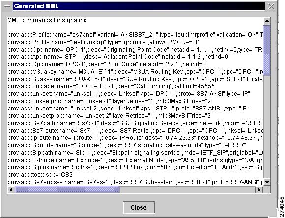
View Generated MML Commands
Cisco VSPT automatically generates MML commands to provision your Cisco PGW 2200 Softswitch and saves these commands in a file to be executed when you deploy the configuration.
To view the MML commands generated from your Cisco VSPT provisioning session, click View > MML.
A screen displaying generated MML commands, similar to the one shown in Figure 4-1, appears.
Figure 4-1 Generated MML Window
View Generated Trunk Group File
To view the trunk group file generated from your Cisco VSPT provisioning session, click View > Trunk Group File.
A screen displaying the generated trunk group file, similar to the one shown in Figure 4-2, appears.
Figure 4-2 Generated Trunk Group File Window

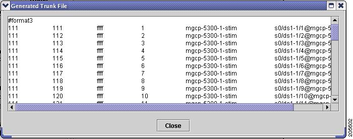
View Generated Trunk File
To view the trunk file generated from your Cisco VSPT provisioning session, click View > Trunk File.
A screen displaying the generated trunk file, similar to the one shown in Figure 4-3, appears.
Figure 4-3 Generated Trunk File Window
Perform an Integrity Check
When provisioning is complete, you can perform an integrity check to prevent possible configuration errors. You can check one or all of the following:
•![]() Integrity for the Cisco PGW 2200 Softswitch signaling configuration
Integrity for the Cisco PGW 2200 Softswitch signaling configuration
•![]() Traffic against the Cisco PGW 2200 Softswitch configuration
Traffic against the Cisco PGW 2200 Softswitch configuration
•![]() Dial plan results
Dial plan results
Use the following procedure to perform an integrity check of the currently open configuration:
Step 1 ![]() Click Tools > Integrity Check. The Integrity Check dialog box appears (Figure 4-4).
Click Tools > Integrity Check. The Integrity Check dialog box appears (Figure 4-4).
Figure 4-4 Integrity Check Dialog Box
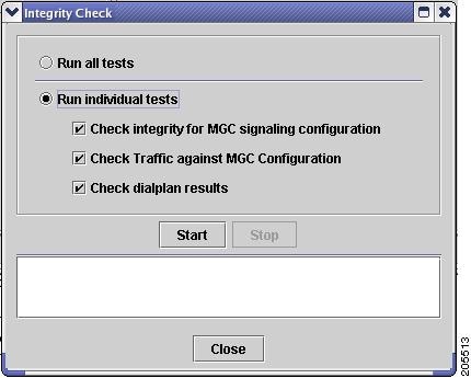
Step 2 ![]() Select the tests you want to run:
Select the tests you want to run:
•![]() Click Run all tests to run all three tests. See "Integrity Check Dialog Box Options" section below for a description of each test.
Click Run all tests to run all three tests. See "Integrity Check Dialog Box Options" section below for a description of each test.
•![]() To run one or more individual tests, click Run individual tests. All tests are checked. Uncheck the tests you do not want to run.
To run one or more individual tests, click Run individual tests. All tests are checked. Uncheck the tests you do not want to run.
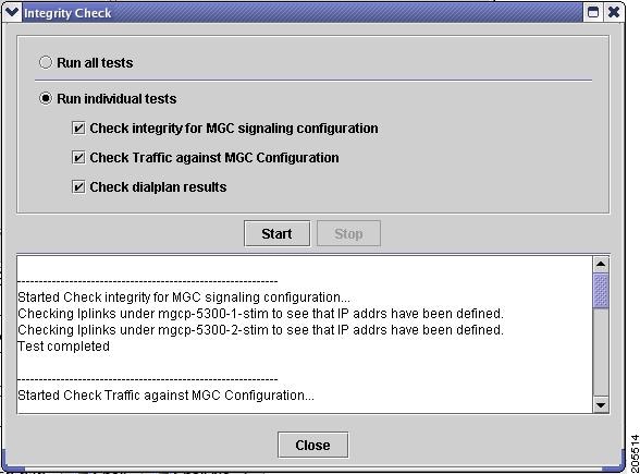
Step 3 ![]() Click Start. Cisco VSPT runs the selected tests.
Click Start. Cisco VSPT runs the selected tests.
When the tests finish, a screen similar to the one in Figure 4-5 appears showing the results of the integrity checks.
Figure 4-5 Integrity Check Results
Integrity Check Dialog Box Options
This section describes the options in the Integrity Check dialog box.
Check Integrity for Cisco PGW 2200 Softswitch Signaling Configuration
When you perform an integrity check for Cisco PGW 2200 Softswitch signaling configuration, the Cisco VSPT does the following:
•![]() Checks that the hostname is specified for Cisco PGW 2200 Softswitch.
Checks that the hostname is specified for Cisco PGW 2200 Softswitch.
•![]() Checks that logins and passwords are specified for Cisco PGW 2200 Softswitch.
Checks that logins and passwords are specified for Cisco PGW 2200 Softswitch.
•![]() Checks that Cisco PGW 2200 Softswitch ipaddrs are specified.
Checks that Cisco PGW 2200 Softswitch ipaddrs are specified.
•![]() Checks that if Cisco PGW 2200 Softswitch failover is specified, the failover IPs are specified.
Checks that if Cisco PGW 2200 Softswitch failover is specified, the failover IPs are specified.
•![]() For IPFAS IPLNK:
For IPFAS IPLNK:
–![]() Ensures that SigSlot/SigPort is specified.
Ensures that SigSlot/SigPort is specified.
–![]() Checks SigSlot/SigPort on the MGX to ensure that the values are valid as specified on the MGX.
Checks SigSlot/SigPort on the MGX to ensure that the values are valid as specified on the MGX.
–![]() Ensures that Cisco PGW 2200 Softswitch ports and MGX ports match on the IPLNK.
Ensures that Cisco PGW 2200 Softswitch ports and MGX ports match on the IPLNK.
–![]() Checks that all IPLNKs under a single IPFASPATH map to the same port number.
Checks that all IPLNKs under a single IPFASPATH map to the same port number.
•![]() Checks that point codes are correctly provisioned and only one true opc is defined.
Checks that point codes are correctly provisioned and only one true opc is defined.
•![]() Checks that if there are Lawful Intercept Mediation Device (LIMD) sigpaths, one iplink is defined at least.
Checks that if there are Lawful Intercept Mediation Device (LIMD) sigpaths, one iplink is defined at least.
•![]() Checks that a trunk group profile contains some property provisioning.
Checks that a trunk group profile contains some property provisioning.
•![]() Checks that signaling path for an external node is correctly provisioned. (External node types are MGX8260, VISM, VXSM (VXSM was added in Release 2.7(3) Patch 2).)
Checks that signaling path for an external node is correctly provisioned. (External node types are MGX8260, VISM, VXSM (VXSM was added in Release 2.7(3) Patch 2).)
•![]() Checks that if the property IPInScreening of one SIP signaling service is set to 2, a default trunk group of SIP_IN trunk type using that SIP signaling service is provisioned (Added in Release 2.7(3) Patch 3).
Checks that if the property IPInScreening of one SIP signaling service is set to 2, a default trunk group of SIP_IN trunk type using that SIP signaling service is provisioned (Added in Release 2.7(3) Patch 3).

Note ![]() The number of IPFAS sessions using a given port is displayed because some IPLNKs might use different port IDs.
The number of IPFAS sessions using a given port is displayed because some IPLNKs might use different port IDs.
Check Traffic Against Cisco PGW 2200 Softswitch Configuration
When you perform an integrity check of traffic against the Cisco PGW 2200 Softswitch configuration, the Cisco VSPT does the following:
•![]() Check if there are corresponding IPFASPATH signaling services with corresponding IPLNKs when D channels are defined as FAS and NFAS PRI in the trunk group/trunk section.
Check if there are corresponding IPFASPATH signaling services with corresponding IPLNKs when D channels are defined as FAS and NFAS PRI in the trunk group/trunk section.
•![]() Checks if there are any defined IPFASPATH signaling services defining a D channel but no corresponding trunk group or trunk in the traffic information with a corresponding NFAS/FAS PRI.
Checks if there are any defined IPFASPATH signaling services defining a D channel but no corresponding trunk group or trunk in the traffic information with a corresponding NFAS/FAS PRI.
•![]() Checks that signaling services defined for trunk groups exist in the configuration.
Checks that signaling services defined for trunk groups exist in the configuration.
•![]() Checks CIC conflicts for trunk groups sharing the same SS7 or IP signaling service. (One CIC is used only in one trunk among the trunk groups sharing the same SS7 or IP signaling service.)
Checks CIC conflicts for trunk groups sharing the same SS7 or IP signaling service. (One CIC is used only in one trunk among the trunk groups sharing the same SS7 or IP signaling service.)
Check Dial Plan Results
When you perform an integrity check for the dial plan, the Cisco PGW 2200 Softswitch does the following:
•![]() Checks that the route names in the route results actually exist on the traffic side
Checks that the route names in the route results actually exist on the traffic side
•![]() Checks that the resultset is not empty
Checks that the resultset is not empty
•![]() Checks that the resultset contains an existing conditional route, codecString, and CPCMOD
Checks that the resultset contains an existing conditional route, codecString, and CPCMOD
•![]() Checks that the IN_TRIGGER result contains a valid STP/SCP index which is defined in MGC Config window > SS7 Subsystem
Checks that the IN_TRIGGER result contains a valid STP/SCP index which is defined in MGC Config window > SS7 Subsystem
Background Information
In the dial plan, the Bdigittree maps a called digit string to select the desired result. For the Bdigittree, the digit string indicates what it should do when a call destined for the number xxx-xxxx is received. The selected value identifies what to do with the call. The result set contains results (processing actions for the call). One of the results can be a route result. Associated with the route result is the name of a route (from the traffic branch) that shows the trunk groups that exist within a route. This implies that the call should be routed onto the specified route and routed onto one of the trunk groups within the route.
Deploy a Configuration
When you finish defining a configuration, you must deploy that configuration to the Cisco PGW 2200 Softswitch.
Note ![]() A new configuration should not be deployed during times of peak load on the Cisco PGW 2200 Softswitch.
A new configuration should not be deployed during times of peak load on the Cisco PGW 2200 Softswitch.
A configuration created in Cisco VSPT can be deployed to a Cisco PGW 2200 Softswitch as a new configuration or incrementally. Deploying incrementally allows you to quickly apply modifications to an existing configuration without having to redeploy the entire configuration. Cisco VSPT also allows you to visually check the incremental commands it generates before deploying those commands to the Cisco PGW 2200 Softswitch.
If the Cisco PGW 2200 Softswitch has SSH enabled, you should deploy the configuration using the SSH protocol.
Deploying a New Configuration
Use the following procedure to deploy a new configuration.
Note ![]() If you want to delete a component and plan to reuse the component name, first delete the component, deploy the session, and verify that the component name has been deleted before reusing the name.
If you want to delete a component and plan to reuse the component name, first delete the component, deploy the session, and verify that the component name has been deleted before reusing the name.
Step 1 ![]() Click Tools > Deploy on the main Cisco VSPT menu. The Protocol Options dialog box appears.
Click Tools > Deploy on the main Cisco VSPT menu. The Protocol Options dialog box appears.
Step 2 ![]() Select the desired protocol:
Select the desired protocol:
•![]() Choose SSH if SSH is enabled on the device.
Choose SSH if SSH is enabled on the device.
•![]() Choose None if SSH is not enabled on the device.
Choose None if SSH is not enabled on the device.
The screen shown in Figure 4-6 appears.
Figure 4-6 Deploying a Configuration
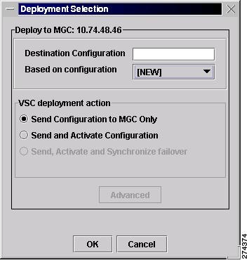
Step 3 ![]() Indicate how you want to deploy the configuration:
Indicate how you want to deploy the configuration:
•![]() To deploy the configuration to the Cisco PGW 2200 Softswitch only, do one of the following:
To deploy the configuration to the Cisco PGW 2200 Softswitch only, do one of the following:
–![]() If you want to send the configuration to the Cisco PGW 2200 Softswitch but not activate it, click the button next to Send Configuration to MGC Only.
If you want to send the configuration to the Cisco PGW 2200 Softswitch but not activate it, click the button next to Send Configuration to MGC Only.
–![]() If you want to send the configuration to the Cisco PGW 2200 Softswitch and activate it, click the button next to Send and Activate Configuration.
If you want to send the configuration to the Cisco PGW 2200 Softswitch and activate it, click the button next to Send and Activate Configuration.
–![]() If you have a continuous-service configuration with two Cisco PGW 2200 Softswitch hosts, click the button next to Send, Activate and Synchronize failover. The configuration is saved on the active host and copied to the standby host. You must restart the standby server after reconfiguration to apply changes.
If you have a continuous-service configuration with two Cisco PGW 2200 Softswitch hosts, click the button next to Send, Activate and Synchronize failover. The configuration is saved on the active host and copied to the standby host. You must restart the standby server after reconfiguration to apply changes.
Note ![]() If you select an option other than NEW, the Advanced button is enabled. For information about the options this button provides, see the "Configuring an Incremental Deployment" section.
If you select an option other than NEW, the Advanced button is enabled. For information about the options this button provides, see the "Configuring an Incremental Deployment" section.
Step 4 ![]() Choose a configuration in the Based on configuration drop-down list.
Choose a configuration in the Based on configuration drop-down list.
This list displays all existing configurations on the selected Cisco PGW 2200 Softswitch and the [LAST IMPORT] and [NEW] options. You can choose one of the following options from the drop-down list:
•![]() LAST IMPORT—The Cisco VSPT compares your provisioning session to the last imported configuration and deploys only changes you have made.
LAST IMPORT—The Cisco VSPT compares your provisioning session to the last imported configuration and deploys only changes you have made.
Note ![]() The LAST IMPORT option allows multiple users to modify an existing configuration. However, they must each be modifying a different area of the configuration for this option to work properly.
The LAST IMPORT option allows multiple users to modify an existing configuration. However, they must each be modifying a different area of the configuration for this option to work properly.
•![]() NEW—Your entire provisioning session is deployed as a new configuration.
NEW—Your entire provisioning session is deployed as a new configuration.
•![]() Existing Configurations—Cisco VSPT imports the selected configuration from the Cisco PGW 2200 Softswitch, compares the differences between that configuration and your current provisioning session, and deploys changes you have made.
Existing Configurations—Cisco VSPT imports the selected configuration from the Cisco PGW 2200 Softswitch, compares the differences between that configuration and your current provisioning session, and deploys changes you have made.
Note ![]() Since you are deploying a new configuration, make sure to choose the NEW option in the Based on configuration drop-down list.
Since you are deploying a new configuration, make sure to choose the NEW option in the Based on configuration drop-down list.
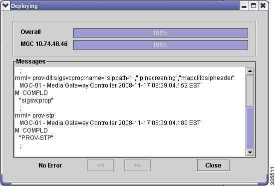
Step 5 ![]() Click OK. The screen shown in Figure 4-7 appears and displays the status as the current provisioning session is deployed.
Click OK. The screen shown in Figure 4-7 appears and displays the status as the current provisioning session is deployed.
Figure 4-7 Deployment Progress
Note ![]() In a continuous-service configuration, the XECfgParm.dat file on each machine must be configured. If you experience problems, verify the integrity of the XECfgParm.dat files on both machines. See Chapter 3 in the Cisco Media Gateway Controller Software Release 9.7 Installation and Configuration Guide.
In a continuous-service configuration, the XECfgParm.dat file on each machine must be configured. If you experience problems, verify the integrity of the XECfgParm.dat files on both machines. See Chapter 3 in the Cisco Media Gateway Controller Software Release 9.7 Installation and Configuration Guide.
Configuring an Incremental Deployment
An incremental deployment allows you to modify an existing configuration and deploy only the modified areas to the Cisco PGW 2200 Softswitch. Modifications can be made more quickly, and errors affecting unmodified areas are minimized. In addition, provisioning modifications made by other users in separate areas are not affected.
Note ![]() The Cisco PGW 2200 Softswitch does not support some incremental deployment processes. If you have a problem with an incremental deployment, examine the MML commands to ensure that you have properly configured the desired components. Modify the component presenting the problem, or cancel the deployment and redeploy the component as a new configuration.
The Cisco PGW 2200 Softswitch does not support some incremental deployment processes. If you have a problem with an incremental deployment, examine the MML commands to ensure that you have properly configured the desired components. Modify the component presenting the problem, or cancel the deployment and redeploy the component as a new configuration.
Use the following procedure to configure an incremental deployment:
Step 1 ![]() Follow Step 1 through Step 4 in the "Deploying a New Configuration" section.
Follow Step 1 through Step 4 in the "Deploying a New Configuration" section.
Step 2 ![]() Click Advanced in the window shown in Figure 4-6. The screen shown in Figure 4-8 appears.
Click Advanced in the window shown in Figure 4-6. The screen shown in Figure 4-8 appears.
Figure 4-8 Incremental Deployment Component Selector
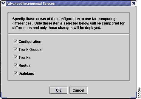
If you have only made configuration changes to one or more of the areas listed, you can direct the Cisco VSPT to compare only those areas with the current configuration, and your modifications can be deployed more quickly.
Note ![]() If you select areas in this window, be sure to include all areas that you have modified.
If you select areas in this window, be sure to include all areas that you have modified.
Step 3 ![]() Select one or more component types to deploy, and click OK.
Select one or more component types to deploy, and click OK.
Step 4 ![]() Go to Step 5 in the "Deploying a New Configuration" section, and complete the procedure described there. When you click OK, a screen similar to the one displayed in Figure 4-9 appears.
Go to Step 5 in the "Deploying a New Configuration" section, and complete the procedure described there. When you click OK, a screen similar to the one displayed in Figure 4-9 appears.
Figure 4-9 Confirm MML Commands
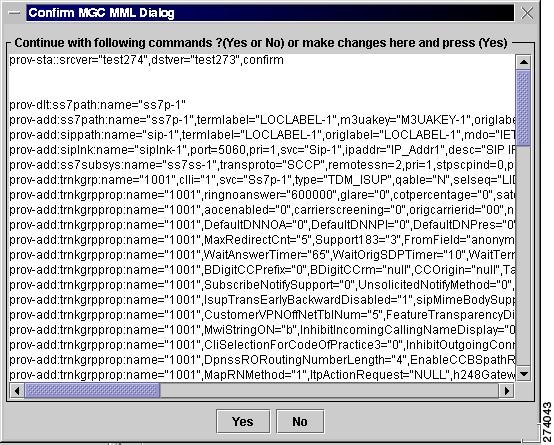
Step 5 ![]() Inspect the MML commands, modify them if desired, and click Yes to continue with the incremental deployment. Click No to reissue the deployment as a new configuration.
Inspect the MML commands, modify them if desired, and click Yes to continue with the incremental deployment. Click No to reissue the deployment as a new configuration.
Remote Shell
Cisco VSPT provides a utility to open a Telnet session and connect directly to a device. Once you have established your Telnet connection, you can log in to the device and execute commands remotely on the device through the Telnet interface.
If you have installed SSH for Cisco VSPT and the remote device also supports SSH, you can select the ssh utility instead of Telnet.
Use the following procedure to open a Telnet or ssh session with a network device:
Step 1 ![]() Click Tools > Remote Shell. A screen similar to that shown in Figure 4-10 appears.
Click Tools > Remote Shell. A screen similar to that shown in Figure 4-10 appears.
Figure 4-10 Select Remote Network Device
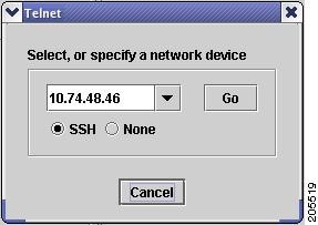
Step 2 ![]() Select the device and connection method:
Select the device and connection method:
•![]() Select a device from the dropdown list, or enter the name or IP address of a device on your network.
Select a device from the dropdown list, or enter the name or IP address of a device on your network.
•![]() Select the connection method, either SSH (if the device supports it) or None for Telnet.
Select the connection method, either SSH (if the device supports it) or None for Telnet.
•![]() Click Go.
Click Go.
A Telnet or SSH window opens for you to log in to the device.
MGC Viewer
The MGC Viewer allows you to view, activate, remove, and synchronize configurations on the Cisco PGW 2200 Softswitch. If you are communicating with an SSH-enabled Cisco PGW 2200 Softswitch, you can use SSH instead of Telnet for the communication.
Use the following procedure to view configurations on a Cisco PGW 2200 Softswitch:
Step 1 ![]() Click Tools > MGC viewer on the main Cisco VSPT menu. On the MGC Configuration screen that appears, click File > Open MGC. The Protocol Options dialog box appears.
Click Tools > MGC viewer on the main Cisco VSPT menu. On the MGC Configuration screen that appears, click File > Open MGC. The Protocol Options dialog box appears.
Step 2 ![]() Select the desired protocol:
Select the desired protocol:
•![]() Choose SSH if SSH is enabled on the device.
Choose SSH if SSH is enabled on the device.
•![]() Choose None if SSH is not enabled on the device.
Choose None if SSH is not enabled on the device.
A screen similar to the one in Figure 4-11 appears.
Figure 4-11 Select Cisco PGW 2200 Softswitches
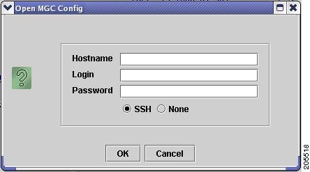
Step 3 ![]() Enter the host name of the Cisco PGW 2200 Softswitch in the Hostname box, enter the Cisco PGW 2200 Softswitch login and password, and click OK. A screen similar to the one in Figure 4-12 appears and lists all configurations on the specified Cisco PGW 2200 Softswitch.
Enter the host name of the Cisco PGW 2200 Softswitch in the Hostname box, enter the Cisco PGW 2200 Softswitch login and password, and click OK. A screen similar to the one in Figure 4-12 appears and lists all configurations on the specified Cisco PGW 2200 Softswitch.
Figure 4-12 MGC Configurations
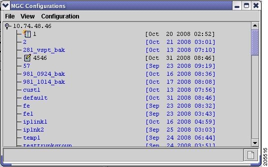
Step 4 ![]() Click Configuration on the MGC Viewer menu bar, and select one of the following actions:
Click Configuration on the MGC Viewer menu bar, and select one of the following actions:
•![]() Activate—Activate the configuration.
Activate—Activate the configuration.
•![]() Synchronize—Synchronize with the current configuration.
Synchronize—Synchronize with the current configuration.
•![]() Delete—Delete the configuration.
Delete—Delete the configuration.
Cisco BAMS Configuration
The Cisco BAMS Configuration utility enables you to create, copy, modify, and deploy a configuration for the Cisco BAMS server. You can use Cisco VSPT to provision general Cisco BAMS system items, including general information, zones, trunk group information, measurements, system, and other items.
You can find provisioning procedures in the section, "Starting a Cisco BAMS Provisioning Session," and the section "Cisco BAMS Server Configuration" in Chapter 3 of the Cisco Media Gateway Controller Software Release 9 Provisioning Guide at
http://www.cisco.com/en/US/docs/voice_ip_comm/pgw/9/provisioning/guide/R9GUI.html
Before you use Cisco PGW 2200 Softswitch to provision a Cisco BAMS, you need to provision the Cisco BAMS and the Cisco PGW 2200 Softswitch for using the Cisco BAMS.
•![]() Provision the Cisco PGW 2200 Softswitch for using BAMS—See the section "Configuring the Cisco MGC for Using BAMS," and the section "Enabling SFTP on Cisco BAMS and the Cisco PGW 2200" in Chapter 2 at
Provision the Cisco PGW 2200 Softswitch for using BAMS—See the section "Configuring the Cisco MGC for Using BAMS," and the section "Enabling SFTP on Cisco BAMS and the Cisco PGW 2200" in Chapter 2 at
http://www.cisco.com/en/US/docs/voice_ip_comm/pgw/bams/3.30/guide/330ch2.html
•![]() Provision the Cisco BAMS—See the section "Configuring BAMS" in Chapter 2 at the preceding link and the section "Updating the Poll Table" in Chapter 5 at
Provision the Cisco BAMS—See the section "Configuring BAMS" in Chapter 2 at the preceding link and the section "Updating the Poll Table" in Chapter 5 at
http://www.cisco.com/en/US/docs/voice_ip_comm/pgw/bams/3.30/guide/330ch5.html
Note ![]() To set up an active Cisco PGW 2200 Softswitch paired with a standby one for a Cisco BAMS, you need to provision both active and standby Cisco PGW 2200 Softswitches.
To set up an active Cisco PGW 2200 Softswitch paired with a standby one for a Cisco BAMS, you need to provision both active and standby Cisco PGW 2200 Softswitches.
State Operation
The State Operation utility enables you to query the active configuration on the Cisco PGW 2200 Softswitch for the state of managed objects. After a query, you can modify the state of an object and apply the update to the Cisco PGW 2200 Softswitch. If you are querying the state of an SSH-enabled Cisco PGW 2200 Softswitch, you can use SSH instead of Telnet for the communication.
Use the following procedure to query the state of managed objects on the Cisco PGW 2200 Softswitch:
Step 1 ![]() Click Tools > State Operation on the main Cisco VSPT menu. The Protocol Options dialog box appears.
Click Tools > State Operation on the main Cisco VSPT menu. The Protocol Options dialog box appears.
Step 2 ![]() Select the desired protocol:
Select the desired protocol:
•![]() Choose SSH if SSH is enabled on the device.
Choose SSH if SSH is enabled on the device.
•![]() Choose None if SSH is not enabled on the device.
Choose None if SSH is not enabled on the device.
A screen similar to the one in Figure 4-13 appears.
Figure 4-13 State Operation Dialog
Step 3 ![]() Click OK.
Click OK.
The Cisco VSPT queries the Cisco PGW 2200 Softswitch.
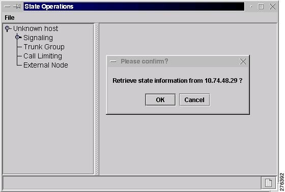
Step 4 ![]() Expand the hierarchical tree in the left pane of the State Operations window to locate and highlight the object. See Figure 4-14
Expand the hierarchical tree in the left pane of the State Operations window to locate and highlight the object. See Figure 4-14
Figure 4-14 State Operations

Step 5 ![]() Click Modify at the bottom of the right pane. A screen wimilar to the one in Figure 4-15 displays.
Click Modify at the bottom of the right pane. A screen wimilar to the one in Figure 4-15 displays.
Figure 4-15 Modify State
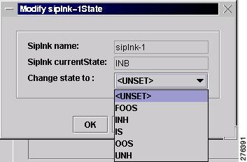
Step 6 ![]() From this window, you can modify the state by choosing the desired state in the Change state to drop-down list. Click OK to save the change. You are back to the window in Figure 4-14.
From this window, you can modify the state by choosing the desired state in the Change state to drop-down list. Click OK to save the change. You are back to the window in Figure 4-14.
Step 7 ![]() Click Modify to change the state in this window, and click Commit to change the state on the Cisco PGW 2200 Softswitch. To query the object again, click Refresh.
Click Modify to change the state in this window, and click Commit to change the state on the Cisco PGW 2200 Softswitch. To query the object again, click Refresh.
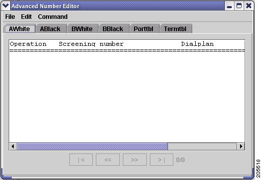
Advanced Number Editor
You can use the advanced number editor to edit the call screening list, the ported number table, and the number termination table:
•![]() A-number Whitelist
A-number Whitelist
•![]() A-number Blacklist
A-number Blacklist
•![]() B-number Whitelist
B-number Whitelist
•![]() B-number Blacklist
B-number Blacklist
•![]() Ported Number Table
Ported Number Table
•![]() Number Termination Table
Number Termination Table
Click Tools > Advanced Number Editor and you see a window similar to the one in Figure 4-16. For details on the advanced number editor, see Chapter 3 of the Cisco PGW 2200 Softswitch Release 9 Dial Plan Guide.
Figure 4-16 Advanced Number Editor Window
Perform an Audit
You can use an audit to ensure that both the Cisco PGW 2200 Softswitch and a Cisco BAMS server supporting the Cisco PGW 2200 Softswitch host have consistently configured signal paths. The audit involves examining signal path and bearer channel data on both servers, comparing the data, and reporting any differences. If you are auditing an SSH-enabled Cisco PGW 2200 Softswitch, you can use SSH instead of Telnet for the communication.
Use the following procedure to perform an audit:
Step 1 ![]() Click Tools > Audit.
Click Tools > Audit.
The Protocol Options dialog box appears (see Figure 4-17).
Figure 4-17 Audit
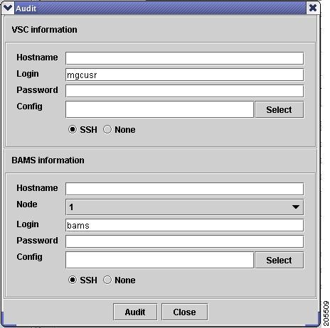
Step 2 ![]() Enter the Cisco PGW 2200 Softswitch hostname, login, and password in the top pane of the window.
Enter the Cisco PGW 2200 Softswitch hostname, login, and password in the top pane of the window.
Step 3 ![]() To specify the configuration to audit, click Select, highlight the configuration to audit, and click OK.
To specify the configuration to audit, click Select, highlight the configuration to audit, and click OK.
Step 4 ![]() Enter the Cisco BAMS hostname, login, and password in the bottom pane of the window.
Enter the Cisco BAMS hostname, login, and password in the bottom pane of the window.
Step 5 ![]() To specify the configuration to audit, click Select, highlight the configuration to audit, and click OK.
To specify the configuration to audit, click Select, highlight the configuration to audit, and click OK.
Step 6 ![]() Click Audit. A screen similar to the one displayed in Figure 4-18 appears.
Click Audit. A screen similar to the one displayed in Figure 4-18 appears.
Figure 4-18 Audit Results
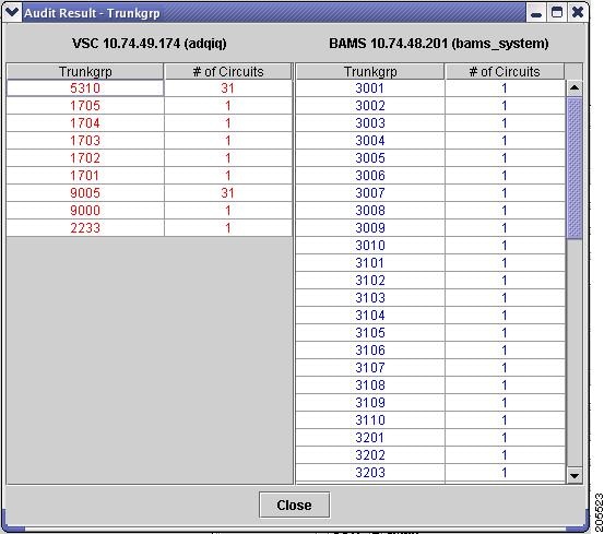
The left pane displays the signal path and bearer channel data configured on the Cisco PGW 2200 Softswitch host, and the right pane displays the same data configured on the Cisco BAMS server.
Back Up and Restore
The Cisco VSPT backup and restore tool allows you to create, modify, and delete scheduled backups and restores hourly, daily, weekly, monthly, or on demand.
You can do a backup or restore on any of the following devices if they have been configured for the Cisco PGW 2200 Softswitch:
•![]() Cisco PGW 2200 Softswitch Host—Active configuration or entire Cisco PGW 2200 Softswitch system
Cisco PGW 2200 Softswitch Host—Active configuration or entire Cisco PGW 2200 Softswitch system
•![]() Cisco Catalyst 2900XL—Running-config and image in Flash
Cisco Catalyst 2900XL—Running-config and image in Flash
•![]() Cisco Catalyst 5500—For switch module and RSM, configuration and image in Flash
Cisco Catalyst 5500—For switch module and RSM, configuration and image in Flash
•![]() Cisco Catalyst 6509—For switch module and MSFC, configuration and image in Flash
Cisco Catalyst 6509—For switch module and MSFC, configuration and image in Flash
•![]() Cisco ITP-L (SLT) 2600—Running-config and image in Flash
Cisco ITP-L (SLT) 2600—Running-config and image in Flash
•![]() Cisco BAMS Phase 3—Active configuration
Cisco BAMS Phase 3—Active configuration
•![]() Cisco HSI Adjunct Server—Active configuration
Cisco HSI Adjunct Server—Active configuration
The backup and restore tool also provides the status of each activity and generates user-viewable status logs.
Before you begin
•![]() You must have selected an appropriate backup host and enabled TFTP on that machine.
You must have selected an appropriate backup host and enabled TFTP on that machine.
•![]() Make sure there is enough space on the backup host for the backup files.
Make sure there is enough space on the backup host for the backup files.
•![]() You must start Cisco VSPT from a UNIX shell with the backup ID. The backup ID is specified during installation. You can start Cisco VSPT in either of two ways:
You must start Cisco VSPT from a UNIX shell with the backup ID. The backup ID is specified during installation. You can start Cisco VSPT in either of two ways:
–![]() If Cisco VSPT is launched from Cisco MGC Node Manager (Cisco MNM), you must have started the Cisco EMF client with the backup ID. If your normal ID is different from the backup ID, you must start a new Cisco MNM session with the backup ID.
If Cisco VSPT is launched from Cisco MGC Node Manager (Cisco MNM), you must have started the Cisco EMF client with the backup ID. If your normal ID is different from the backup ID, you must start a new Cisco MNM session with the backup ID.
–![]() From the command line in a UNIX shell opened with the backup ID.
From the command line in a UNIX shell opened with the backup ID.
•![]() Make sure the timeout value is adequate for the backup process to be finished. To adjust the timeout values, modify the following two parameters in the configuration file: /opt/CSCOvsp28/classes/com/cisco/transpath/dart/editor/configEditor.properties.
Make sure the timeout value is adequate for the backup process to be finished. To adjust the timeout values, modify the following two parameters in the configuration file: /opt/CSCOvsp28/classes/com/cisco/transpath/dart/editor/configEditor.properties.
–![]() Modify the value of parameter DefaultTimeOut to adjust the timeout value for shell command. The default value is three minutes.
Modify the value of parameter DefaultTimeOut to adjust the timeout value for shell command. The default value is three minutes.
–![]() Modify the value of parameter Backup.timeout to adjust the timeout value for system backup and FTP session. The default value is 30 minutes.
Modify the value of parameter Backup.timeout to adjust the timeout value for system backup and FTP session. The default value is 30 minutes.
If you receive an error message, "Time out interact..."during the backup process, you can modify the value of Backup.timeout to a larger number to solve the problem.
Note ![]() The system backup could take long time and the backup files could be very large. It is strongly recommended that you perform the system backup at non-busy time.
The system backup could take long time and the backup files could be very large. It is strongly recommended that you perform the system backup at non-busy time.
Backup and Restore Process
The backup process includes three main steps:
•![]() Cisco VSPT connects to the managed component using Telnet or, if the component is SSH enabled, using a secure ssh connection. (You must have specified the component's IP address, login, and password, and you must have selected the security policy. To select the policy, choose None or SSH, in the Add... Schedule dialog box when you set up the backup.)
Cisco VSPT connects to the managed component using Telnet or, if the component is SSH enabled, using a secure ssh connection. (You must have specified the component's IP address, login, and password, and you must have selected the security policy. To select the policy, choose None or SSH, in the Add... Schedule dialog box when you set up the backup.)
•![]() The managed component makes a TFTP connection (as a client) to the TFTP server on the backup host.
The managed component makes a TFTP connection (as a client) to the TFTP server on the backup host.
•![]() The configuration file of the managed component is transferred to the backup host. TFTP is used whether or not SSH is enabled. (You must have specified the backup host's IP address, Login, and Password in the Add Schedule dialog box.) TFTP must be enabled on the backup host.
The configuration file of the managed component is transferred to the backup host. TFTP is used whether or not SSH is enabled. (You must have specified the backup host's IP address, Login, and Password in the Add Schedule dialog box.) TFTP must be enabled on the backup host.
The restore process includes four main steps:
•![]() Cisco VSPT connects to the managed component using Telnet or, if the component is SSH enabled, using a secure ssh connection.
Cisco VSPT connects to the managed component using Telnet or, if the component is SSH enabled, using a secure ssh connection.
•![]() The managed component makes a TFTP connection (as a client) to the TFTP server on the backup host.
The managed component makes a TFTP connection (as a client) to the TFTP server on the backup host.
•![]() As the TFTP client, the managed component gets the backup file (tar file) from the backup host and places it in a temporary location (/tmp).
As the TFTP client, the managed component gets the backup file (tar file) from the backup host and places it in a temporary location (/tmp).
•![]() The managed component untars the tar file from the temporary location into the /opt/CiscoMGC/etc/cust_specific/ directory location.
The managed component untars the tar file from the temporary location into the /opt/CiscoMGC/etc/cust_specific/ directory location.
Schedule a Backup or Restore
To schedule a backup or restore, use the following procedure:
Step 1 ![]() Click Tools > Backup and Restore on the main Cisco VSPT menu bar.
Click Tools > Backup and Restore on the main Cisco VSPT menu bar.
The Backup and Restore window appears, listing components that can have scheduled backups.
Step 2 ![]() Click the component for which you want to schedule a backup.
Click the component for which you want to schedule a backup.
In the following example, the Cisco PGW 2200 Softswitch component configuration is backed up. On the right side of the window, the schedules for that component appear.
Note ![]() If you want to perform a restore, you must have a backup file already created and available on the Cisco PGW 2200 Softswitch or on another managed component.
If you want to perform a restore, you must have a backup file already created and available on the Cisco PGW 2200 Softswitch or on another managed component.
Step 3 ![]() In the Add/View Schedules pane, click Add.
In the Add/View Schedules pane, click Add.
Figure 4-19 Add/View Schedules
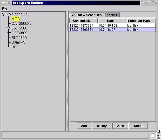
A screen similar to the one shown in Figure 4-20 appears.
Figure 4-20 Add MGC Schedule
Note ![]() The fields available in the dialog box vary according to the component selected.
The fields available in the dialog box vary according to the component selected.
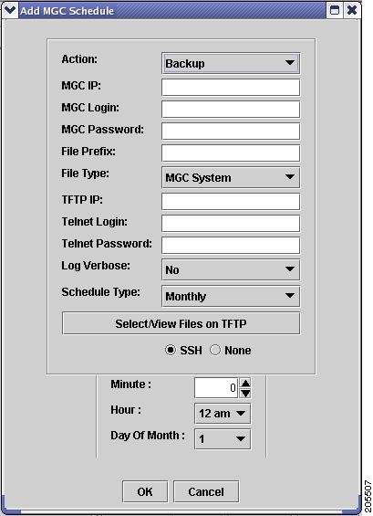
Step 4 ![]() From the Action drop-down list, choose the action you want to perform.
From the Action drop-down list, choose the action you want to perform.
Choices are Backup and Restore.
If you choose Restore, a screen similar to the one shown in Figure 4-21 appears.
Figure 4-21 Restore
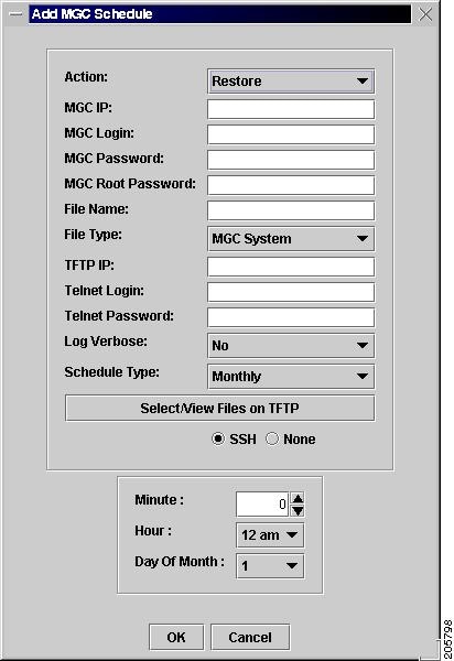
Step 5 ![]() Enter information for the component you are backing up:
Enter information for the component you are backing up:
•![]() Enter the IP address of the Cisco PGW 2200 Softswitch.
Enter the IP address of the Cisco PGW 2200 Softswitch.
•![]() Enter the Cisco PGW 2200 Softswitch login and password.
Enter the Cisco PGW 2200 Softswitch login and password.
Note ![]() If you want to perform a restore for the Cisco PGW 2200 Softswitch system, you must enter the Cisco PGW 2200 Softswitch root password as well.
If you want to perform a restore for the Cisco PGW 2200 Softswitch system, you must enter the Cisco PGW 2200 Softswitch root password as well.
Step 6 ![]() In the File Name field, enter a name for the backup file.
In the File Name field, enter a name for the backup file.
Step 7 ![]() From the File Type drop-down list, choose one of the following:
From the File Type drop-down list, choose one of the following:
•![]() MML Config—Backs up MML files for the active configuration on the Cisco PGW 2200 Softswitch
MML Config—Backs up MML files for the active configuration on the Cisco PGW 2200 Softswitch
•![]() MGC System—Backs up MML files for the active configuration (as does MML Config), plus the Times Ten database, the XEconfigParm.dat file, and UNIX configuration files
MGC System—Backs up MML files for the active configuration (as does MML Config), plus the Times Ten database, the XEconfigParm.dat file, and UNIX configuration files
Step 8 ![]() Enter TFTP information for the server to which you are backing up (destination for the configuration file):
Enter TFTP information for the server to which you are backing up (destination for the configuration file):
•![]() Enter the IP address of the TFTP server.
Enter the IP address of the TFTP server.
•![]() Enter the TFTP login and password.
Enter the TFTP login and password.
Step 9 ![]() Specify whether or not to use verbose log mode. Verbose mode records all commands issued by the Cisco VSPT and any system responses.
Specify whether or not to use verbose log mode. Verbose mode records all commands issued by the Cisco VSPT and any system responses.
Step 10 ![]() Choose whether to connect to the component you are backing up using SSH or Telnet (None).
Choose whether to connect to the component you are backing up using SSH or Telnet (None).
Note ![]() The operation itself is executed with TFTP or in the case of the Cisco PGW 2200 Softswitch system, FTP.
The operation itself is executed with TFTP or in the case of the Cisco PGW 2200 Softswitch system, FTP.
Step 11 ![]() Choose the schedule type. Choices include
Choose the schedule type. Choices include
•![]() Monthly
Monthly
•![]() Daily
Daily
•![]() Hourly
Hourly
•![]() Weekly
Weekly
•![]() Now
Now
•![]() Later
Later
Step 12 ![]() Choose the protocol to use for connecting to and logging in to the component you are backing up:
Choose the protocol to use for connecting to and logging in to the component you are backing up:
•![]() Choose SSH to use ssh.
Choose SSH to use ssh.
•![]() Choose None to use Telnet.
Choose None to use Telnet.
Step 13 ![]() Choose the hour and minute that the backup should begin.
Choose the hour and minute that the backup should begin.
Step 14 ![]() Click OK. The backup activity is scheduled, and the scheduled event appears in the schedule list.
Click OK. The backup activity is scheduled, and the scheduled event appears in the schedule list.
After the backup has been completed, you can view the status of the activity, and acknowledge or clear the status log file from the Status tab. The backup file with the name you specified is available for use with Cisco VSPT.
Check Status of Backup or Restore
The Cisco VSPT generates status logs that provide information about each scheduled activity. The status log displays the following information for the activity:
•![]() Date and time when activity began
Date and time when activity began
•![]() Success or failure
Success or failure
•![]() File name on the TFTP server
File name on the TFTP server
•![]() Directory of configuration files
Directory of configuration files
•![]() Image file name
Image file name
If you specified verbose log mode, the status log also displays the sequence of commands issued by the Cisco VSPT and any system responses.
Use the following procedure to check the status of a backup or restore activity:
Step 1 ![]() In the left pane of the backup and restore tool window, click the device that has been backed up or restored. Click the Status tab in the right pane.
In the left pane of the backup and restore tool window, click the device that has been backed up or restored. Click the Status tab in the right pane.
Step 2 ![]() Highlight the backup or restore for which you want information.
Highlight the backup or restore for which you want information.
Step 3 ![]() Select the appropriate button for the action you want to perform. Choices are
Select the appropriate button for the action you want to perform. Choices are
•![]() Show status—Displays the log file for the activity.
Show status—Displays the log file for the activity.
•![]() Acknowledge—Removes the text from the Status window and deletes the log file from the server.
Acknowledge—Removes the text from the Status window and deletes the log file from the server.
•![]() Clear—Removes the text from the Status window, but the log file remains on the server.
Clear—Removes the text from the Status window, but the log file remains on the server.
 Feedback