- Preface
- Overview of Cisco MNM
- Configuring Network Devices for Management
- Getting Started with Cisco MNM
- Setting Up Cisco MNM Security
- Deploying Your Network in Cisco MNM
- Managing Faults with Cisco MNM
- Managing the Performance of Cisco MNM Devices
- Other Network Management Tasks
- Cisco MNM System Administration
- Alarm Message Reference
- Performance Measurements Reference
- Troubleshooting Cisco MNM
- Index
Cisco Media Gateway Controller Node Manager User Guide, Release 2.7(3)
Bias-Free Language
The documentation set for this product strives to use bias-free language. For the purposes of this documentation set, bias-free is defined as language that does not imply discrimination based on age, disability, gender, racial identity, ethnic identity, sexual orientation, socioeconomic status, and intersectionality. Exceptions may be present in the documentation due to language that is hardcoded in the user interfaces of the product software, language used based on RFP documentation, or language that is used by a referenced third-party product. Learn more about how Cisco is using Inclusive Language.
- Updated:
- November 11, 2007
Chapter: Getting Started with Cisco MNM
- Starting and Quitting a Cisco MNM Session
- Opening, Closing, and Switching Cisco MNM Applications
- Basic Operations in Cisco MNM
- Using the Map Viewer
- Understanding Cisco MNM Dialog Boxes
Getting Started with Cisco MNM
Revised: December 16, 2009, OL-14480-06
This chapter describes the basics of working with Cisco Media Gateway Controller (MGC) Node Manager (MNM). Topics include
•![]() Starting and Quitting a Cisco MNM Session
Starting and Quitting a Cisco MNM Session
•![]() Opening, Closing, and Switching Cisco MNM Applications
Opening, Closing, and Switching Cisco MNM Applications
•![]() Basic Operations in Cisco MNM
Basic Operations in Cisco MNM
•![]() Understanding Cisco MNM Dialog Boxes
Understanding Cisco MNM Dialog Boxes
Starting and Quitting a Cisco MNM Session
This section describes how to start and quit a Cisco MNM session.

Note ![]() If you are using VNC on Solaris 10 to access Cisco MNM, see the instructions at the following URL for help with installing and configuring the VNC on the Solaris 10 platform from the Sun Microsystems website:
If you are using VNC on Solaris 10 to access Cisco MNM, see the instructions at the following URL for help with installing and configuring the VNC on the Solaris 10 platform from the Sun Microsystems website:
http://www.sun.com/bigadmin/jsp/descFile.jsp?url=descAll/install_and_configu
In the configuration procedure described in the site at the above URL, use the following line to replace the corresponding line when you are editing /etc/dt/config/Xservers.
:1 Local local_uid@console root /opt/sfw/bin/Xvnc :1 -httpd /opt/sfw/vnc/classes -depth 24 -geometry 1024x768 -r fbwait 120000 -rfbauth /opt/sfw/vnc/.vnc/passwd -rfbport 5901
-httpport 5801 -fp tcp/localhost:7100 -alwaysshared -co /usr/openwin/lib/X11/rgb
-fp /usr/openwin/lib/X11/fonts/misc/, /usr/openwin/lib/X11/fonts/75dpi/
Starting a Cisco MNM Session
You must start a Cisco MNM session when Cisco EMF is running. Because the Cisco EMF is the element management framework upon which Cisco MNM is built, you need go into the <CEMF_ROOT> directory to start a Cisco MNM session. Use the following steps to start a Cisco MNM session:
Step 1 ![]() Log in as root.
Log in as root.
Step 2 ![]() From the command line on the terminal window enter
From the command line on the terminal window enter
#cd <CEMF_ROOT>/bin
Where <CEMF_ROOT> is the Cisco MNM installation root directory (for example, /opt/cemf).
Step 3 ![]() Verify that Cisco EMF is running.
Verify that Cisco EMF is running.
Step 4 ![]() Enter
Enter
# cemf query
You should see CEMF Manager 3.2 initialized, followed by a list of running Cisco EMF processes.
Step 5 ![]() If Cisco EMF is not running, start it by entering the following command:
If Cisco EMF is not running, start it by entering the following command:
# cemf start
Step 6 ![]() From the command line on the terminal window, enter
From the command line on the terminal window, enter
# <CEMF_ROOT>/bin/cemf session
Where <CEMF_ROOT> is the Cisco MNM installation root directory (for example, /opt/cemf).
The Cisco EMF Login window displays (see Figure 3-1).
Figure 3-1 Cisco EMF Login Window
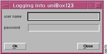
Step 7 ![]() Enter your user name and password, and click OK.
Enter your user name and password, and click OK.
Note ![]() The default user name and password are each admin.
The default user name and password are each admin.
If an unknown user name or password is entered, an error message displays. You are given three attempts to enter a valid user name and corresponding password. After three invalid entries, the session does not start and the Login window closes.
When a valid user name and password are entered, the session starts and the Cisco EMF launchpad window displays (see Figure 3-2).
Step 8 ![]() Continue to the "Opening an Application" section.
Continue to the "Opening an Application" section.
Quitting a Cisco MNM Session
You can quit a Cisco MNM session at any time. Quitting Cisco MNM closes any open applications or dialog boxes, but does not stop Cisco EMF.
Note ![]() To stop Cisco EMF, you must be the root user.
To stop Cisco EMF, you must be the root user.
Use the following procedure to quit a Cisco MNM session:
Step 1 ![]() Do one of the following:
Do one of the following:
•![]() From the File menu, select Quit.
From the File menu, select Quit.
•![]() Press Ctrl-Q.
Press Ctrl-Q.
•![]() Click the Close tool on the toolbar.
Click the Close tool on the toolbar.
You are asked if you want to quit the Cisco EMF Manager system.
Step 2 ![]() Click Yes to quit the session.
Click Yes to quit the session.
All active applications are closed and the session terminates. Cisco EMF continues to run.
Opening, Closing, and Switching Cisco MNM Applications
Cisco MNM applications are the major groupings of network management functions. They include
•![]() Map Viewer—You can view, build, and monitor a network with Map Viewer. You can monitor the networks using network object connections.
Map Viewer—You can view, build, and monitor a network with Map Viewer. You can monitor the networks using network object connections.
•![]() Object Group Manager—You can organize network elements into object groups with the Object Group manager. You can create, delete, and modify object groups.
Object Group Manager—You can organize network elements into object groups with the Object Group manager. You can create, delete, and modify object groups.
•![]() Access Manager—The Access manager allows an administrator to set up users and user groups, assign passwords, and define access parameters.
Access Manager—The Access manager allows an administrator to set up users and user groups, assign passwords, and define access parameters.
•![]() Event Browser—Clicking the Events button initiates the Event Browser and Query Editor. You can create object groups or browse events from these windows.
Event Browser—Clicking the Events button initiates the Event Browser and Query Editor. You can create object groups or browse events from these windows.
•![]() Discovery—Because Cisco MNM requires a login and password to communicate with a device, the Cisco EMF Automatic Discovery feature is not supported by Cisco MNM. If you want the Cisco MNM to discover (and can automatically rediscover) components and configurations of a device, you must first deploy the device and enter the following information into Cisco MNM: IP address, host name, and login information of the device, as described in Chapter 5, "Deploying Your Network in Cisco MNM."
Discovery—Because Cisco MNM requires a login and password to communicate with a device, the Cisco EMF Automatic Discovery feature is not supported by Cisco MNM. If you want the Cisco MNM to discover (and can automatically rediscover) components and configurations of a device, you must first deploy the device and enter the following information into Cisco MNM: IP address, host name, and login information of the device, as described in Chapter 5, "Deploying Your Network in Cisco MNM."
•![]() Cisco MNM Manuals—Opens a Mozilla browser window and displays links to the following documents:
Cisco MNM Manuals—Opens a Mozilla browser window and displays links to the following documents:
–![]() Cisco Media Gateway Controller Node Manager end-user guides
Cisco Media Gateway Controller Node Manager end-user guides
You can also see these documents at
http://www.cisco.com/en/US/products/sw/netmgtsw/ps1912/products_user_guide_list.html.
Note ![]() If the Cisco MNM is installed co-resident with another CEMF element manager, a button for that product's manual also displays.
If the Cisco MNM is installed co-resident with another CEMF element manager, a button for that product's manual also displays.
•![]() Event Manager
Event Manager
–![]() Notify—You can create notification profiles, each of which is a notification that should be carried out as a result of the profile being triggered.
Notify—You can create notification profiles, each of which is a notification that should be carried out as a result of the profile being triggered.
–![]() Thresholds—You can configure the management system to actively monitor the network and notify the operator when some aspect of the network performance has deviated from preset criteria.
Thresholds—You can configure the management system to actively monitor the network and notify the operator when some aspect of the network performance has deviated from preset criteria.
–![]() Event Groups—You can filter and organize events based on specified criteria, such as severity, state, or type of network element, and then create a scoreboard to show the state of the group at a glance.
Event Groups—You can filter and organize events based on specified criteria, such as severity, state, or type of network element, and then create a scoreboard to show the state of the group at a glance.
–![]() PreFilter—You can prefilter some messages collected in Cisco MNM according to the defined rules.
PreFilter—You can prefilter some messages collected in Cisco MNM according to the defined rules.
Once you have started a Cisco MNM session, you can open, close, and switch between applications.
Opening an Application
The Cisco EMF launchpad (shown in Figure 3-2) is used to access Cisco MNM applications. You can open multiple applications, and you can open more than one instance of an application.
Figure 3-2 Cisco EMF Launchpad
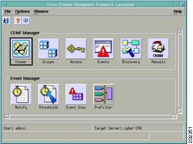
Use the following procedure to open an application:
On the launchpad, click the icon to open the desired application. A busy icon and a message in the status bar display while it is opening.
Note ![]() If an application is already open, it displays in the drop-down menu on the Window toolbar. Click Window, and choose the desired application.
If an application is already open, it displays in the drop-down menu on the Window toolbar. Click Window, and choose the desired application.
Closing an Application
Closing an application closes only the current instance of the application. Other instances of the application are unaffected. For example, if you separately opened an Event Browser for a Cisco BAMS and an Event Browser for a Cisco PGW 2200 Softswitch host, closing the Cisco PGW 2200 Softswitch host Event Browser window does not close the Cisco BAMS Event Browser window.
Use one of the following procedures to close an application:
•![]() Choose File > Close.
Choose File > Close.
•![]() Click the window Close button.
Click the window Close button.
•![]() If the window has a toolbar, click the Close tool
If the window has a toolbar, click the Close tool  .
.
•![]() Press Alt-F4.
Press Alt-F4.
Switching Between Open Application Windows
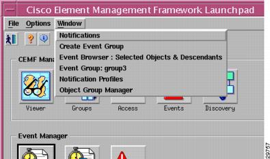
Working in Cisco MNM often involves having several windows open at the same time. You can view the list of open windows and switch between them from the drop-down menu on the Window toolbar (see Figure 3-3).
Use the following steps to switch between windows:
Step 1 ![]() Click Window on the toolbar. The drop-down menu displays and lists all open windows.
Click Window on the toolbar. The drop-down menu displays and lists all open windows.
Figure 3-3 Window Pull-Down Menu
Step 2 ![]() Choose a window.
Choose a window.
Basic Operations in Cisco MNM
This section describes basic operations in Cisco MNM:
•![]() Using the mouse, shortcut keys, or toolbar to access Cisco MNM features
Using the mouse, shortcut keys, or toolbar to access Cisco MNM features
•![]() Selecting items in lists
Selecting items in lists
•![]() Printing the contents of a window
Printing the contents of a window
•![]() Viewing Cisco MNM status information
Viewing Cisco MNM status information
Using the Mouse
The left, middle, and right mouse buttons are used for the following Cisco MNM functions:
•![]() Click the left mouse button to
Click the left mouse button to
–![]() Select
Select
–![]() Activate
Activate
–![]() Set the location of the cursor
Set the location of the cursor
•![]() Click the middle mouse button to
Click the middle mouse button to
–![]() Copy
Copy
–![]() Move
Move
–![]() Drag
Drag
•![]() To access context menus, click the right mouse button on a managed object within an application such as the Map Viewer, the Object Group Manager, or events in the Event Browser.
To access context menus, click the right mouse button on a managed object within an application such as the Map Viewer, the Object Group Manager, or events in the Event Browser.
Using Shortcut Keys
Ctrl-Key
Standard Cisco MNM menus are available on the toolbar. You can click to select items from the menus or you can enter shortcut keys, as shown in Table 3-1 and Table 3-2.
|
|
|
Ctrl-Q |
Quit |
Ctrl-W |
Close |
Ctrl-P |
|
Ctrl-S |
Save |
Ctrl-N |
New |
Ctrl-O |
Open |
|
|
|
Ctrl-Z |
Undo |
Ctrl-X |
Cut |
Ctrl-C |
Copy |
Ctrl-V |
Paste |
Ctrl-A |
Select all |
Ctrl-D |
Deselect all |
Note ![]() When a menu option is grayed out, it is not available for selection.
When a menu option is grayed out, it is not available for selection.
Alt-Key
Items in the Cisco MNM menus and dialog boxes may be displayed with the first (initial) letter underlined (for example, Actions.) This means that you can select this option either by clicking the mouse, or by pressing Alt-A.

Tip ![]() You can use the X windows standard Alt-4 to close the current window.
You can use the X windows standard Alt-4 to close the current window.
Using the Toolbar
In Cisco MNM application windows, a toolbar contains tool buttons for commonly used menu options. You can toggle the toolbar on or off and display or hide tooltips.
In Figure 3-4, the toolbar contains tool buttons for the following functions common to many dialog boxes:
•![]() Close the current window.
Close the current window.
•![]() Print the contents of the window.
Print the contents of the window.
Figure 3-4 Example of a Toolbar

Note ![]() If you have problems printing the contents of a window, consult your system administrator to verify that your operating system is configured for printing.
If you have problems printing the contents of a window, consult your system administrator to verify that your operating system is configured for printing.
•![]() Toggle dynamic update mode to allow viewing or not viewing real-time changes.
Toggle dynamic update mode to allow viewing or not viewing real-time changes.
•![]() Refresh the window to update the information when dynamic update mode is off.
Refresh the window to update the information when dynamic update mode is off.
•![]() Acknowledge that you have seen dynamically updated dialog box changes.
Acknowledge that you have seen dynamically updated dialog box changes.
Hiding or Showing the Toolbar
To toggle the display of the toolbar for the current window, choose Options > Show Toolbar.
Hiding or Showing Tooltips
A tooltip provides a brief description of a toolbar button or window panel. The tooltips appear when the cursor is positioned over the item. You can choose to show or hide tooltips.
To toggle the display of tooltips for the toolbar in the current window, choose Options > Enable Tooltip.
Selecting from Lists
To perform an operation on more than one item, you can select:
•![]() A block of items
A block of items
•![]() Multiple items in different areas of a list
Multiple items in different areas of a list
•![]() All items
All items
You can also deselect all items. For instructions, see the "Use the following steps to deselect all items:" task
Use the following steps to select a block of items:
Step 1 ![]() Click the first item in the block.
Click the first item in the block.
The item is highlighted.
Step 2 ![]() Press and hold the Shift key.
Press and hold the Shift key.
Step 3 ![]() Click the last item in the block.
Click the last item in the block.
Step 4 ![]() Release the Shift key.
Release the Shift key.
All items between the first and last item are highlighted.
Use the following steps to select multiple items in different areas of a list:
Step 1 ![]() Click the first item.
Click the first item.
The item is highlighted.
Step 2 ![]() Press Ctrl and click the next item you want to select.
Press Ctrl and click the next item you want to select.
The item is highlighted.
Step 3 ![]() Repeat Step 2 and Step 3 until all the desired items are highlighted.
Repeat Step 2 and Step 3 until all the desired items are highlighted.
Use the following steps to select all items:
Step 1 ![]() Place the cursor anywhere in the window.
Place the cursor anywhere in the window.
Step 2 ![]() Press and hold the right mouse button.
Press and hold the right mouse button.
A context menu displays.
Step 3 ![]() Choose Select All.
Choose Select All.
Note ![]() This option is not available in all windows.
This option is not available in all windows.
All items in the list are highlighted.
Use the following steps to deselect all items:
Step 1 ![]() Place the cursor anywhere in the window.
Place the cursor anywhere in the window.
Step 2 ![]() Press and hold the right mouse button.
Press and hold the right mouse button.
A context menu displays.
Step 3 ![]() Choose Deselect.
Choose Deselect.
Note ![]() This option is not available in all windows.
This option is not available in all windows.
All items in the list are deselected.
Printing the View Displayed in the Window
In most cases, you can print the contents of a window.
Note ![]() If you have problems printing the contents of a window, ask your system administrator to verify that your operating system is configured for printing.
If you have problems printing the contents of a window, ask your system administrator to verify that your operating system is configured for printing.
To print the contents of the current window, do one of the following:
•![]() From the File menu, choose Print.
From the File menu, choose Print.
•![]() Press Ctrl-P.
Press Ctrl-P.
•![]() Click the Print tool on the toolbar.
Click the Print tool on the toolbar.
The current view is printed.
Viewing Cisco MNM Status Information
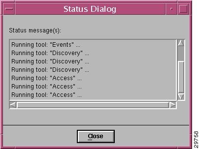
The status bar at the bottom of most windows displays status information about the current Cisco MNM application status (not about network status).
To view previous status messages, double-click in the status bar. The Status Dialog displays, as shown in Figure 3-5.
Figure 3-5 Status Dialog
Using the Map Viewer
The Map Viewer organizes the network display into various views and is the starting point for most Cisco MNM network management operations. Each view represents a different way of containing and grouping the network elements, such as device type, Cisco PGW 2200 Softswitch node, and physical or network view.
In the Map Viewer you can
•![]() Deploy an entire network or a single new device.
Deploy an entire network or a single new device.
•![]() See at a glance which devices have generated alarms. Because the alarm display is propagated from the originating object up through the containing objects, you can quickly drill down to find the source of the problem.
See at a glance which devices have generated alarms. Because the alarm display is propagated from the originating object up through the containing objects, you can quickly drill down to find the source of the problem.
Note ![]() Propagation applies to the node and physical views. Alarms are not propagated in device views.
Propagation applies to the node and physical views. Alarms are not propagated in device views.
•![]() Identify information about a device by its graphical representation. State icon, color, and cross-hatching pattern are some of the indicators that give you a quick graphical read of the network condition.
Identify information about a device by its graphical representation. State icon, color, and cross-hatching pattern are some of the indicators that give you a quick graphical read of the network condition.
•![]() Access network devices by navigating through one of the views to the desired object and then right-clicking to open any of the Cisco MNM services relevant to that device.
Access network devices by navigating through one of the views to the desired object and then right-clicking to open any of the Cisco MNM services relevant to that device.
•![]() View the network in different ways. For example, you can use the physical view to see where devices are located, the device view to perform an operation on all devices of a particular type, and the node view to see node-specific elements such as signaling components.
View the network in different ways. For example, you can use the physical view to see where devices are located, the device view to perform an operation on all devices of a particular type, and the node view to see node-specific elements such as signaling components.
Note ![]() The term "object" refers to the graphical representation of a network element in Cisco MNM and the term "device" refers to the real-world counterpart that is represented and manipulated by the object.
The term "object" refers to the graphical representation of a network element in Cisco MNM and the term "device" refers to the real-world counterpart that is represented and manipulated by the object.
This section describes the basics of how to use the Map Viewer. The Map Viewer display is based on the Cisco MNM object model of the network. For an explanation of the concepts and some of the technical details behind the Map Viewer, see the "How Cisco MNM Builds a Model for the Network" section on page 1-9.
This section describes
•![]() The Map Viewer window and views.
The Map Viewer window and views.
•![]() How to expand a view, to get to an object, and collapse a view.
How to expand a view, to get to an object, and collapse a view.
•![]() How to read the visual symbols associated with objects in the Map Viewer.
How to read the visual symbols associated with objects in the Map Viewer.
•![]() How to use the context menu to open a Cisco MNM service for the current object. (This is your entry point to most network management functions.)
How to use the context menu to open a Cisco MNM service for the current object. (This is your entry point to most network management functions.)
For more information on the Map Viewer, refer to "Map Viewer" in the Cisco EMF online help.
Map Viewer Window
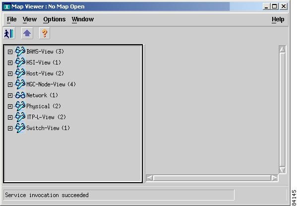
Until you have deployed a network in Cisco MNM, the Map Viewer displays only empty container objects (see Figure 3-6 for an example).
Figure 3-6 Map Viewer Before a Network Is Deployed
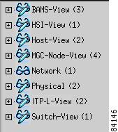
When you deploy a network, (see Chapter 5, "Deploying Your Network in Cisco MNM") the views are populated with the graphical objects that represent your network devices. Initially, the view is collapsed (see Figure 3-7).
Figure 3-7 Map Viewer After Deployment
When a view is expanded, the Map Viewer looks like the illustration shown in Figure 3-8.
Figure 3-8 Typical Appearance of the Map Viewer
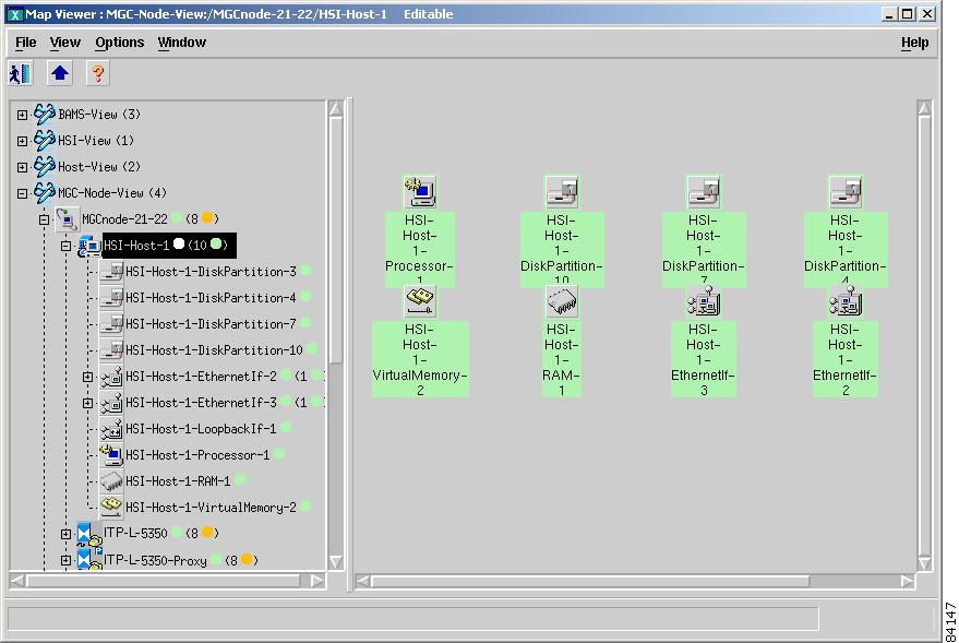
•![]() The Map Viewer window is divided into two panes. The left pane is a hierarchy browser. The right pane displays a map of the object selected in the right pane. The map is a detailed depiction of the selected device or site.
The Map Viewer window is divided into two panes. The left pane is a hierarchy browser. The right pane displays a map of the object selected in the right pane. The map is a detailed depiction of the selected device or site.
•![]() If you want to resize the hierarchy browser pane and map pane, position your cursor over the boundary and dragging.
If you want to resize the hierarchy browser pane and map pane, position your cursor over the boundary and dragging.
•![]() Use the scroll bars to view all information in the left and right panes.
Use the scroll bars to view all information in the left and right panes.
•![]() You can open a service on a device object by right-clicking the object and choosing the service from the context menu. To open a service on multiple devices, select the devices, and then right-click.
You can open a service on a device object by right-clicking the object and choosing the service from the context menu. To open a service on multiple devices, select the devices, and then right-click.
Note ![]() The context menu displays the list of services available for the selected device or devices. Services available depend on your access privileges. If multiple objects are selected, only services common to all selected objects are available.
The context menu displays the list of services available for the selected device or devices. Services available depend on your access privileges. If multiple objects are selected, only services common to all selected objects are available.
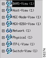
Map Viewer Views
This section describes the various Map Viewer views.
Node View
The node view shows all the devices in the node, as well as the MGC host signaling, dial plan, and trunking components.
Note ![]() Dial Plan Components on Cisco PGW 2200 Softswitch are no longer supported on Cisco MNM Release 2.7(3) Patch 4.
Dial Plan Components on Cisco PGW 2200 Softswitch are no longer supported on Cisco MNM Release 2.7(3) Patch 4.
Use the node view to
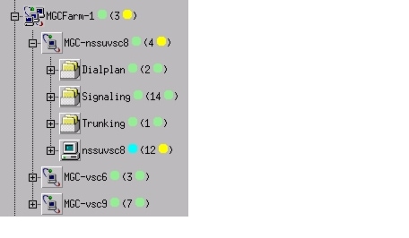
•![]() Deploy a node and devices within a node. In a conventional node, you deploy one or a pair of MGC hosts in the node. In a farm, you deploy a farm in the node, and then deploy one or a pair of MGC hosts in the farm, as shown in Figure 3-13.
Deploy a node and devices within a node. In a conventional node, you deploy one or a pair of MGC hosts in the node. In a farm, you deploy a farm in the node, and then deploy one or a pair of MGC hosts in the farm, as shown in Figure 3-13.
•![]() View alarm propagation. Alarms are propagated from child devices to parent devices anywhere in the node, and you can drill down through the tree to find the element raising the alarm.
View alarm propagation. Alarms are propagated from child devices to parent devices anywhere in the node, and you can drill down through the tree to find the element raising the alarm.
•![]() View signaling, trunking, and dial plan information.
View signaling, trunking, and dial plan information.
•![]() Open applications for signaling, trunking, and dial plan components.
Open applications for signaling, trunking, and dial plan components.
Figure 3-9 shows an example of the node view. Figure 3-10, Figure 3-11, and Figure 3-12 show expansions of the signaling, trunking, and dial plan folders. Figure 3-13 shows an example of a farm folder.
Figure 3-9 Node View
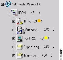
Figure 3-10 Signaling Folder
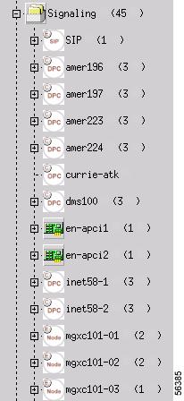
Figure 3-11 Trunking Folder
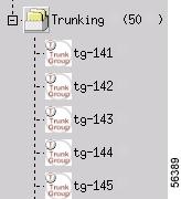
Figure 3-12 Dial Plan Folder
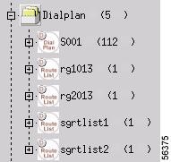
Figure 3-13 Farm Folder
Device View
The device view groups devices by type. Use the device view to view and manage all the devices of a particular type.
Note ![]() Alarms are not propagated in device views. Use the node view or physical view to propagate alarms.
Alarms are not propagated in device views. Use the node view or physical view to propagate alarms.
Tip ![]() To open a Cisco MNM service for a group of devices, open the service from the device view. The dialog box lists all the devices. You can select each desired device in turn.
To open a Cisco MNM service for a group of devices, open the service from the device view. The dialog box lists all the devices. You can select each desired device in turn.
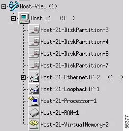
MGC Host View
The MGC host view shows all Cisco PGW 2200 Softswitch hosts. Use host view to
•![]() View and manage all hosts
View and manage all hosts
•![]() View and manage host system components, such as disks, RAM, virtual memory, processor, and interfaces
View and manage host system components, such as disks, RAM, virtual memory, processor, and interfaces
See Figure 3-14 for an example of MGC host view.
Figure 3-14 MGC Host View
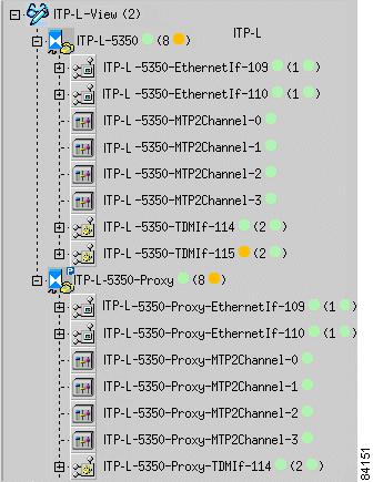
Cisco ITP-L View
Note ![]() Cisco IP Transfer Point LinkExtender (ITP-L) is the new name for Cisco Signaling Link Terminal (SLT).
Cisco IP Transfer Point LinkExtender (ITP-L) is the new name for Cisco Signaling Link Terminal (SLT).
This view shows all the Cisco ITP-Ls, integrated ITPLs, and integrated ITP-L coresident EMs. Use Cisco ITP-L view to
•![]() View and manage all Cisco ITPLs
View and manage all Cisco ITPLs
•![]() View and manage ITP-L interfaces, including TDM interfaces
View and manage ITP-L interfaces, including TDM interfaces
Different icons are used for different types of ITP-Ls, as shown below.
|
|
|
|---|---|
|
|
|
|
Figure 3-15 shows an example of Cisco ITP-L view.
Figure 3-15 Cisco ITP-L View
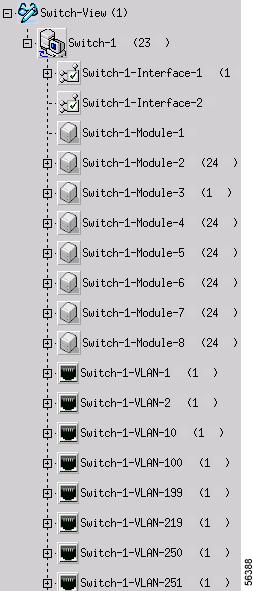
Cisco LAN Switch View
The Cisco LAN switch view shows all Cisco LAN switches. Use this view to
•![]() View and manage all Cisco LAN switches
View and manage all Cisco LAN switches
•![]() View and manage switch components, such as interfaces, modules, and ports
View and manage switch components, such as interfaces, modules, and ports
Figure 3-16 shows an example of Cisco LAN switch view.
Figure 3-16 LAN Switch View
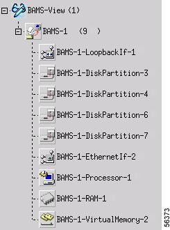
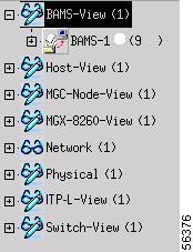
BAMS View
The BAMS view shows all Cisco BAMS machines. Use BAMS view to:
•![]() View and manage all Cisco BAMS machines
View and manage all Cisco BAMS machines
•![]() View and manage Cisco BAMS system components, including disks, RAM, virtual memory, and interfaces
View and manage Cisco BAMS system components, including disks, RAM, virtual memory, and interfaces
Figure 3-17 shows an example of BAMS view.
Figure 3-17 BAMS View
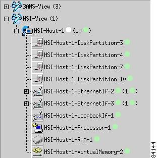
HSI View
The HSI view shows all Cisco HSI servers. Use this view to
•![]() View and manage all Cisco HSI servers
View and manage all Cisco HSI servers
•![]() View and manage Cisco HSI system components, including disk, RAM, memory, and interfaces
View and manage Cisco HSI system components, including disk, RAM, memory, and interfaces
Figure 3-18 shows an example of HSI view.
Figure 3-18 HSI View
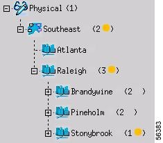
Physical View
The physical view organizes the network by physical location. You can define a hierarchy of regions and sites, such as cities, buildings, and floors (see Figure 3-19). When you deploy the network, you can identify the physical region or site associated with each network device.
Use the physical view to
•![]() Deploy regions and sites—Select the container object for the level you want to deploy. For example, select a Southeast region object to deploy an Atlanta site.
Deploy regions and sites—Select the container object for the level you want to deploy. For example, select a Southeast region object to deploy an Atlanta site.
•![]() View alarm propagation—Alarms are propagated from child devices to parent devices. Drill down through the tree to find the element raising the alarm.
View alarm propagation—Alarms are propagated from child devices to parent devices. Drill down through the tree to find the element raising the alarm.
•![]() Identify where a problem device is located—For example, in Figure 3-19, a problem is indicated in the Stonybrook building, which is propagated upward to the Raleigh and Southeast sites.
Identify where a problem device is located—For example, in Figure 3-19, a problem is indicated in the Stonybrook building, which is propagated upward to the Raleigh and Southeast sites.
•![]() Visualize the actual network.
Visualize the actual network.
Figure 3-19 shows an example of physical view.
Figure 3-19 Physical View
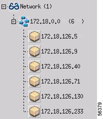
Network View
The network view shows the IP addresses of the network devices.
Figure 3-20 shows an example of network view.
Figure 3-20 Network View
Expanding or Collapsing a View
In the left hierarchy browser pane of the Map Viewer, a plus sign (+) next to an object means it contains other objects and can be expanded. A minus sign (-) means that the object is fully expanded.
•![]() To expand a view, click the + next to the object (see Figure 3-21).
To expand a view, click the + next to the object (see Figure 3-21).
•![]() To drill down to an object, continue expanding the view until you see the desired object.
To drill down to an object, continue expanding the view until you see the desired object.
•![]() To collapse a view, click the - next to the object.
To collapse a view, click the - next to the object.
Tip ![]() When you see an alarm symbol next to an object, drill down if you want to find the object generating the alarm.
When you see an alarm symbol next to an object, drill down if you want to find the object generating the alarm.
Figure 3-21 Expanding a View in the Map Viewer
|
|
|
|
|
Understanding Map Viewer Symbols
Indicators in the Map Viewer reflect the status of the associated object and the occurrence of alarm events. For example, a polling icon indicates that a device or its child is being polled. In this way, the states of the Cisco PGW 2200 Softswitch subobjects are propagated up to the Cisco PGW 2200 Softswitch node object.
Similarly, alarm events, indicated with a color-coded circle in the left pane and a balloon in the right pane, are propagated up in the physical and node view.
For some states, a small symbol is placed near the top of the icon. Cross-hatching is used to indicate state information.
Table 3-3 describes status and event symbols. Table 3-4 displays the color-coding used for alarm events. For more information about alarm events, see Chapter 6, "Managing Faults with Cisco MNM."
|
|
|
|
Red |
Critical |
|
Orange |
Major |
|
Yellow |
Minor |
|
Cyan |
Warning |
|
Green |
Normal |
|
White |
Informational |
Use the Map Viewer to open a function, such as the Performance Manager or a Properties dialog box, for a device or group of devices.Use the following steps to open a function for a device:
Step 1 ![]() In the Map Viewer, navigate to the desired object.
In the Map Viewer, navigate to the desired object.
Note ![]() To open a Cisco MNM function for a group of devices, open the function from the device view. The function dialog box contains a list box of all the devices. You can select each desired device in turn.
To open a Cisco MNM function for a group of devices, open the function from the device view. The function dialog box contains a list box of all the devices. You can select each desired device in turn.
Step 2 ![]() Right-click the object. The context menu is displayed, showing the functions available for the selected object or objects.
Right-click the object. The context menu is displayed, showing the functions available for the selected object or objects.
Step 3 ![]() Choose an option. Table 3-5 summarizes how to access various functions.
Choose an option. Table 3-5 summarizes how to access various functions.
A window opens for the function. For example, if you choose Properties, a Properties dialog box displays the properties of the selected device.
Note ![]() Some functions can be opened from the Event Browser as well as the Map Viewer.
Some functions can be opened from the Event Browser as well as the Map Viewer.
If SSH is enabled, functions that normally invoke Telnet or ftp instead invoke their SSH counterparts, ssh or sftp.
Understanding Cisco MNM Dialog Boxes
Cisco MNM dialog boxes are summarized below:
•![]() Many dialog boxes display popup field descriptions when you pass your pointer over a field name.
Many dialog boxes display popup field descriptions when you pass your pointer over a field name.
•![]() If a container object is selected when the dialog box is opened, the dialog box can be used to view or manipulate properties for any of the selected devices.
If a container object is selected when the dialog box is opened, the dialog box can be used to view or manipulate properties for any of the selected devices.
•![]() Because Cisco MNM supports multiple releases of the Cisco PGW 2200 Softswitch host software, some fields in property dialog boxes may not apply to your release.
Because Cisco MNM supports multiple releases of the Cisco PGW 2200 Softswitch host software, some fields in property dialog boxes may not apply to your release.
•![]() Some dialog boxes display information received from a managed device, and others display information about that device residing in the Cisco MNM database. Toolbar buttons in the dialog box can help you recognize the difference and how the information can be updated.
Some dialog boxes display information received from a managed device, and others display information about that device residing in the Cisco MNM database. Toolbar buttons in the dialog box can help you recognize the difference and how the information can be updated.
The features of Cisco MNM dialog boxes are described in the following sections.
Displaying Field Descriptions
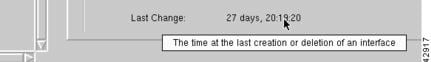
In many dialog boxes, you can view a description of the current field by slowly passing the cursor across the field name (see Figure 3-22).
Figure 3-22 Context Help
Displaying Information for Multiple Devices
You can open a dialog box on multiple devices of the same type. For example, you can
•![]() Select a device view to open a service on all devices of that type
Select a device view to open a service on all devices of that type
•![]() Select a device chassis to open a Properties dialog box on all subcomponents of a particular type
Select a device chassis to open a Properties dialog box on all subcomponents of a particular type
Use the following steps to display information for multiple devices:
Step 1 ![]() Select the devices. See the "Selecting from Lists" section for details on selecting multiple objects.
Select the devices. See the "Selecting from Lists" section for details on selecting multiple objects.
Step 2 ![]() Right-click an option.
Right-click an option.
Note ![]() If an option is not available for the multiple devices you have selected, the option name is dimmed.
If an option is not available for the multiple devices you have selected, the option name is dimmed.
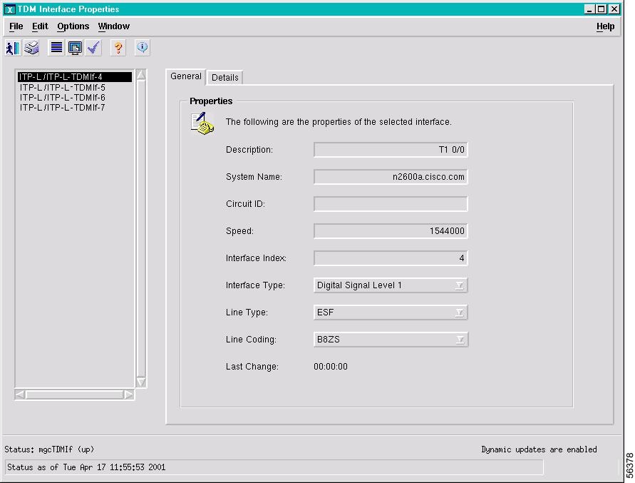
The dialog box opens. A list box in the left pane lists the selected devices. Figure 3-23 shows an example (properties for all TDM interfaces of a Cisco ITP-L).
Step 3 ![]() To view or manipulate information for a particular device, select the device in the list box. The information on the right changes to reflect the current selection.
To view or manipulate information for a particular device, select the device in the list box. The information on the right changes to reflect the current selection.
Figure 3-23 Dialog Box with Information on Multiple Devices
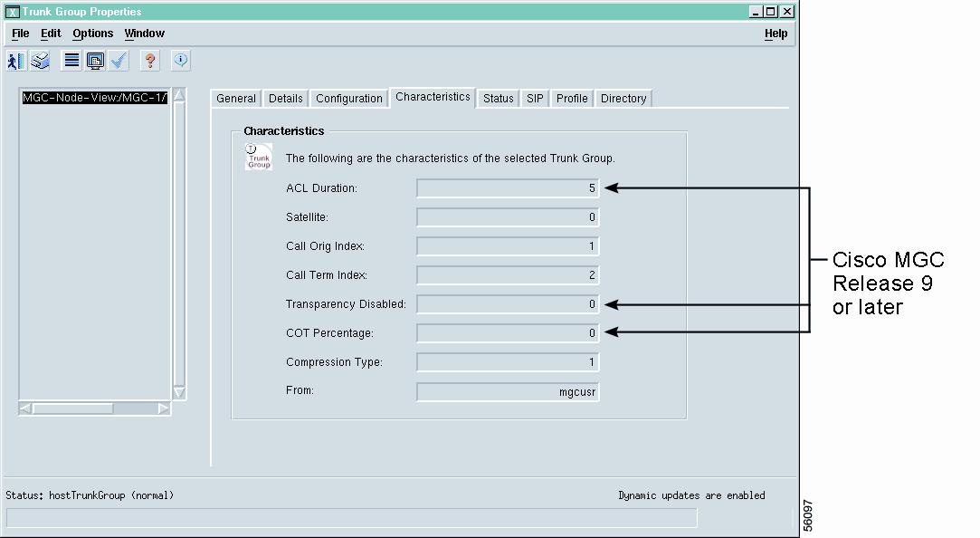
Properties for Multiple Releases of the Cisco PGW 2200 Softswitch Host Software
Each new release of the Cisco PGW 2200 Softswitch host software supports additional properties of the Cisco PGW 2200 Softswitch node elements.
Because Cisco MNM supports multiple Cisco PGW 2200 Softswitch software releases, some dialog boxes may display some fields that might not be applicable to your release of the Cisco PGW 2200 Softswitch software. For example, the Trunk Group Properties dialog box includes properties for Cisco PGW 2200 Softswitch host software Release 7 and 9. It also contains a tab that includes some fields that apply only to Release 9 and are empty if you are using Release 7.
In general, Cisco MNM Release 2.7(3) is tested and supported only on Cisco PGW 2200 Softswitch Releases 9.7(3), 9.6(1), and 9.5(2).
Figure 3-24 A Dialog Box with Properties for Multiple MGC Releases
Working with Various Types of Dialog Box Information
Cisco MNM dialog boxes display two kinds of information about network devices:
•![]() Information that comes from the device itself, such as properties or alarm events, or from Cisco MNM's interaction with the device, such as state information
Information that comes from the device itself, such as properties or alarm events, or from Cisco MNM's interaction with the device, such as state information
•![]() Information that resides in the Cisco MNM database and is used by Cisco MNM to communicate with the device, such as account information
Information that resides in the Cisco MNM database and is used by Cisco MNM to communicate with the device, such as account information
Information that comes from the device is display-only and cannot be edited or modified. To turn on "Dynamic Update" mode for real-time monitoring of the device, see the "Monitoring Dynamically Updated Information" section.
Note ![]() Information that resides in the Cisco MNM database can typically be changed. However, you are changing only the Cisco MNM database and not information stored on the device itself.
Information that resides in the Cisco MNM database can typically be changed. However, you are changing only the Cisco MNM database and not information stored on the device itself.
This section describes
•![]() Monitoring dynamically updated information
Monitoring dynamically updated information
•![]() Making changes to Cisco MNM device information
Making changes to Cisco MNM device information
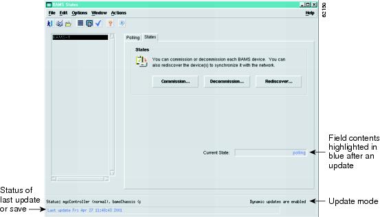
Monitoring Dynamically Updated Information
Many dialog boxes display in near real-time information received from a managed device. With dynamic update on, incoming changes from a device are highlighted in blue (see Figure 3-25). The status bar indicates whether dynamic updating is on or off. This kind of information is display only; it cannot be changed.
Figure 3-25 Dialog Box with Dynamic Updating
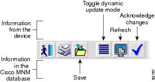
The toolbar in these dialog boxes includes the following three tool buttons (see Figure 3-26) used for managing updates:
•![]() Toggle dynamic update mode, to allow viewing of real-time changes.
Toggle dynamic update mode, to allow viewing of real-time changes.
•![]() Refresh the window, to update the information manually when dynamic update mode is off.
Refresh the window, to update the information manually when dynamic update mode is off.
•![]() Acknowledge changes, to acknowledge that you have seen dynamically updated dialog box changes. When this button is clicked, the blue highlighting is removed.
Acknowledge changes, to acknowledge that you have seen dynamically updated dialog box changes. When this button is clicked, the blue highlighting is removed.
Note ![]() Some dialog boxes include both dynamically updatable information from managed devices and information about the network maintained in the Cisco MNM database. The toolbar in Figure 3-26 also includes a Save tool used for saving changes to database information. (See the "Making Changes to Cisco MNM Device Information" section.)
Some dialog boxes include both dynamically updatable information from managed devices and information about the network maintained in the Cisco MNM database. The toolbar in Figure 3-26 also includes a Save tool used for saving changes to database information. (See the "Making Changes to Cisco MNM Device Information" section.)
Figure 3-26 Dialog Box Toolbar with Dynamic Update and Database Save Functions
Making Changes to Cisco MNM Device Information
Some dialog boxes display information that you can edit. For example, if the login ID for a device changes, you can use the Accounts dialog box for that device to update the information in the Cisco MNM database. In dialog boxes that include editable information, the toolbar includes a Save tool button, as shown in Figure 3-26.
To make changes to the Cisco MNM database, enter the new information, and click the Save tool button.
Note ![]() If you try to make a change but the Save tool button remains dimmed, the field is not editable.
If you try to make a change but the Save tool button remains dimmed, the field is not editable.
Navigating Between Dialog Boxes for a Given Component
For most Cisco PGW 2200 Softswitch node components, you can navigate from one dialog box to another without having to reselect the component in the Map Viewer and right-click. For example, from the File Systems dialog box for a given Cisco BAMS, you can navigate to the Properties, Accounts, States, or Diagnostics dialog box for that Cisco BAMS.
Perform the following steps to navigate from one dialog box to another not-yet-open dialog box for a given component:
Step 1 ![]() In the open dialog box, choose Navigation. A menu appears listing options to open other dialog boxes for this component. See Table 3-6 for a list of components and dialog boxes that provide the Navigation menu.
In the open dialog box, choose Navigation. A menu appears listing options to open other dialog boxes for this component. See Table 3-6 for a list of components and dialog boxes that provide the Navigation menu.
Step 2 ![]() Choose a menu option. The selected dialog box opens.
Choose a menu option. The selected dialog box opens.
Note ![]() Once a dialog box is open, use the Window menu on the toolbar to navigate between windows.
Once a dialog box is open, use the Window menu on the toolbar to navigate between windows.
 Feedback