Cisco Configuration Engine Administration Guide 3.5
Bias-Free Language
The documentation set for this product strives to use bias-free language. For the purposes of this documentation set, bias-free is defined as language that does not imply discrimination based on age, disability, gender, racial identity, ethnic identity, sexual orientation, socioeconomic status, and intersectionality. Exceptions may be present in the documentation due to language that is hardcoded in the user interfaces of the product software, language used based on RFP documentation, or language that is used by a referenced third-party product. Learn more about how Cisco is using Inclusive Language.
- Updated:
- March 29, 2010
Chapter: introduction
- Supported Interfaces
- Cisco IOS Dependencies
- Third-party Software
- Modes of Operation
- Modes of User Authentication
- Configuration Service
- Event Service
Product Overview
This chapter provides a high-level overview of the Cisco Configuration Engine 3.5. It is organized as follows:
•![]() How the Cisco Configuration Engine Works
How the Cisco Configuration Engine Works
•![]() Dynamic ConfigID and EventID Change Synchronization
Dynamic ConfigID and EventID Change Synchronization
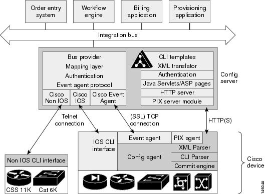
The Cisco Configuration Engine is a network management application that acts as a configuration service for automating the deployment and management of network devices and services (see Figure 1-1).
The Cisco Configuration Engine runs on Linux and Solaris hardware platforms. See Cisco Configuration Engine Installation and Configuration Guide 3.5.
Figure 1-1 Cisco Configuration Engine Architectural Overview

Each Cisco Configuration Engine manages a group of Cisco devices and services they deliver, storing their configurations and delivering them as needed. The Cisco Configuration Engine automates initial configurations and configuration updates by generating device-specific configuration changes, sends them to the device, executes the configuration change, and logs the results.

Note ![]() If you are running devices that use an earlier version of Cisco IOS, or a different operating system, such as Catalyst, you should invoke the Intelligent Modular Gateway for communicating with the device. For more information about Intelligent Modular Gateway, see "Intelligent Modular Gateway" section.
If you are running devices that use an earlier version of Cisco IOS, or a different operating system, such as Catalyst, you should invoke the Intelligent Modular Gateway for communicating with the device. For more information about Intelligent Modular Gateway, see "Intelligent Modular Gateway" section.
The Cisco Configuration Engine utilizes the following popular industry standards and technologies:
•![]() eXtensible Markup Language (XML)
eXtensible Markup Language (XML)
•![]() Java naming directory interface (JNDI)
Java naming directory interface (JNDI)
•![]() Hypertext Transport Protocol (HTTP)
Hypertext Transport Protocol (HTTP)
•![]() Java servlets
Java servlets
•![]() Lightweight Directory Access Protocol (LDAP)
Lightweight Directory Access Protocol (LDAP)
The Cisco Configuration Engine supports two modes of operation (Internal Directory and External Directory) and it includes the following Cisco Configuration Engine components:
•![]() Configuration service (web server, file manager, and namespace mapping server)
Configuration service (web server, file manager, and namespace mapping server)
•![]() Image Service (Cisco IOS images)
Image Service (Cisco IOS images)
•![]() Event service (event gateway)
Event service (event gateway)
•![]() Data service directory (data models and schema)
Data service directory (data models and schema)
•![]() Intelligent Modular Gateway (IMGW)
Intelligent Modular Gateway (IMGW)
The Cisco Configuration Engine can be used as the runtime component for deployment of customer-developed applications. These applications can be developed using the Cisco Configuration Engine Software Development Kit API Reference and Programmer Guide.
Supported Interfaces
The software external interfaces for Cisco Configuration Engine include:
•![]() Unix login
Unix login
•![]() Telnet
Telnet
•![]() Secure Shell (SSH)
Secure Shell (SSH)
Cisco IOS Dependencies
Table 1-1 shows Cisco IOS versions with corresponding versions of Cisco Configuration Engine including feature limitations associated with each version.
Third-party Software
Modes of Operation
There are two modes of system operation for the Cisco Configuration Engine:
•![]() Internal Directory Mode
Internal Directory Mode
•![]() External Directory Mode
External Directory Mode
Modes of User Authentication
There are two modes of user authentication for the Cisco Configuration Engine:
•![]() Authenticate user internally
Authenticate user internally
•![]() Authenticate user externally
Authenticate user externally
The Cisco Configuration Engine user can be authenticated internally or externally. The Cisco Configuration Engine user who logs in is authenticated against the external application. If the external authentication fails, the user is authenticated internally against the Cisco Configuration Engine LDAP Server. For more information about user authentication, see User Authentication.
Directory
Cisco Configuration Engine uses OpenLDAP for Directory services.
OpenLDAP can be configured to use internal or external database as data repository for the Directory. When configured to use internal database (Internal Directory Mode), OpenLDAP stores data in plain files using Berkeley DB library. When configured to use external database (External Directory Mode), OpenLDAP stores data in relational tables using ODBC library
OpenLDAP can also be configured to act as a proxy to forward incoming LDAP requests to another external LDAP server, which provides another possibility for string data in external LDAP server, for example, iPlanet.
Note ![]() GUI access to User Manager and Directory Manager is not available when operating in External Directory mode.
GUI access to User Manager and Directory Manager is not available when operating in External Directory mode.
Configuration Service
The Configuration Service is the core component of the Cisco Configuration Engine. It consists of a configuration server that works in conjunction with configuration agents located at each router. The Configuration Service delivers device and service configurations to Cisco IOS devices for initial configuration and mass reconfiguration by logical groups. Routers receive their initial configuration from the Configuration Service when they start up on the network the first time.
The Configuration Service uses Event Service to send events required to apply configuration changes and receive success and failure notifications.
The configuration server consists of a web server that uses configuration templates and the device-specific configuration information stored in the embedded (Internal Directory mode) or remote (External Directory mode) directory.
Configuration templates are text files containing static configuration information in the form of command-line interface (CLI) commands. In the templates, variables are specified using (LDAP) URLs that reference the device-specific configuration information stored in the directory.
The configuration template includes additional features that allow simple conditional control structures and modular sub-templates in the configuration template (see Chapter 12, "Templates.").
The configuration server uses HTTP to communicate with the Configuration Agent running on the managed Cisco IOS device. The configuration server transfers data in XML format. The configuration agent in the router uses its own XML parser to interpret the configuration data and remove the XML tags from the received configuration.
The configuration agent can also perform a syntax check on received configuration files. The configuration agent can also publish events through the event gateway to indicate the success or failure of the syntax check.
Event Service
The Cisco Configuration Engine uses the Event Service for receipt and generation of events. The Event Agent resides on Cisco IOS devices and facilitates communication between routers and the Event Gateway on the Cisco Configuration Engine.
The Event Service is a highly-scalable publish and subscribe communication method. The Event Service uses subject-based addressing to help messages reach their destination. Subject-based addressing conventions define a simple, uniform namespace for messages and their destinations.
NameSpace Mapper
The Namespace Mapping Service (NSM) allows you to address multiple network devices by a single posting of a publish or subscribe event, and it allows your network administrator to map Cisco-standardized event names to names of his or her choosing.
For example, in a network of 100 routers, there might be 10 that the administrator wants to configure as a VPN (Virtual Private Network). In order to load a configuration into each of these devices, your client application could either publish 10 cisco.mgmt.cns.config.load.<deviceId> events, or the administrator could associate the 10 devices with a common group name and your client application can post the event once. The associated administration steps are:
1. ![]() Using the device management interface, define all the device objects (see Chapter 3, "Device and Subdevice Manager").
Using the device management interface, define all the device objects (see Chapter 3, "Device and Subdevice Manager").
2. ![]() Using NSM administration interface, remap both the subscribe and publish map of cisco.mgmt.cns.mgmt.config.load subject to application.load (see Chapter 7, "Namespace Manager").
Using NSM administration interface, remap both the subscribe and publish map of cisco.mgmt.cns.mgmt.config.load subject to application.load (see Chapter 7, "Namespace Manager").
3. ![]() For example, using the group management interface, group all the devices in the West Coast under a group called "westcoast" (see Chapter 6, "Groups").
For example, using the group management interface, group all the devices in the West Coast under a group called "westcoast" (see Chapter 6, "Groups").
4. ![]() The client application would publish the mapped subject application.load./config/westcoast on the event bus and the devices in the "westcoast" group would get the event. The mapped subject is returned to the client application by the NSM's operational API when querying for the publish mapping for the event cisco.mgmt.cns.config.load.
The client application would publish the mapped subject application.load./config/westcoast on the event bus and the devices in the "westcoast" group would get the event. The mapped subject is returned to the client application by the NSM's operational API when querying for the publish mapping for the event cisco.mgmt.cns.config.load.
Event Gateway
The Event Gateway acts as a relay between the Integration Bus and agent-enabled devices, which enables event-based communication. The Event Gateway uses NSM to map subjects.
Each Event Gateway process can support a maximum of 500 devices. To support more than 500 devices, you should run multiple gateway processes.
During the Setup, you can set the number of concurrent gateway processes to start with either one or both of the following prompts, depending on how you want to setup your Secure Socket Layer (SSL) (see "Encryption" section) communications:
Enter number of Event Gateways that will be started with crypto operation:
Enter number of Event Gateways that will be started with plaintext operation:
Event Gateways that listen on port 11011 and 11012 are Dispatcher Event Gateways which redirect a device connection to a regular plain-text or crypto enabled Event Gateway respectively. For more information see Chapter 6 "Scalability among Event Gateways" in Cisco Configuration Engine Installation and Configuration Guide.
Event Gateway Port Automatic Assignment
Each event gateway can support a maximum of 500 devices. During Zero Touch Deployment (ZTD), the deployment engineer needs to update the bootstrap configuration file for every 500 devices. The event gateway port automatic assignment process helps to eliminate the manual process. When the Cisco Configuration Engine server is configured as the previous section, all the 30,000 devices can be deployed using the same bootstrap configuration file. The following is the sample bootstrap configuration file. The bolded lines are the required commands to support the port automatic assignment.
cns trusted-server all-agents ce-host
cns id hardware-serial
cns id hardware-serial event
cns config initial ce-host status http://ce-host/cns/PostStatus
cns event ce-host keepalive 120 1 reconnect 10
cns config partial ce-host
When a network element connects to Cisco Configuration Engine through the dispatcher event gateway, the Cisco Configuration Engine automatically assigns a port to the network element. The network element saves that information and connects to the designated Cisco Configuration Engine port. The Cisco Configuration Engine can manage a device after the device connects to a none-Cisco Configuration Engine well-known port (ports other than 11011 and 11012).
Dynamic Template and Object
The original servlet, com.cisco.cns.config.Config, gets the configuration template from the attribute value of the Device Object in the configuration server data store (LDAP server), parses the template, and does string substitution on parameters inside the template. It is tightly coupled with the template that is assigned to the device and the attributes of device object.
The new servlet, DynaConfig, loosens the restriction so that the template can be assigned dynamically and the parameter values can be obtained from other objects in data store.
This servlet gets PathInfo information by means of HttpServletRequest.getPathInfo(), parse it, and gets the related template name and object reference. The structure of PathInfo is:
/<argument name>=<argument value>.
Data Structures
The feature of dynamic template and object utilizes PathInfo, which is passed from the client side to the servlets. The structure of PathInfo, which the servlet can understand is in following format:
[/<argument name>=<value>]*
The argument and format for dynamic template and object is:
[/cfgtpl=value[/object=value]]
For more information about Dynamic Template and Object, see Cisco Configuration Engine Software Development Kit API Reference and Programmer Guide .
Image Service
The Image Service is an automated, scalable, and secure mechanism designed to distribute Cisco IOS images and related software updates to Cisco IOS devices that have Cisco Intelligence Agents.
All the image upgrading decisions are made by the image server. These decisions are based on the inventory response information returned by the image agent.
imageInventoryResponse Message
The imageInventoryResponse message contains an imageInventoryReport XML document. This report contains information about:
•![]() The running image on the system
The running image on the system
•![]() The systems hardware resources
The systems hardware resources
•![]() The various file systems and files on the device.
The various file systems and files on the device.
The imageInventoryResponse is a response to an imageInventoryRequest. The resources requested by the tags in the request are sent in the imageInventoryResponse message. The messageID element from the request is included in the messageID element of the response message.
For the devices hardware resources, the minimum information reported is:
•![]() Size of the system RAM available to run an image.
Size of the system RAM available to run an image.
•![]() Name(s) of the system (hostname and, imageID).
Name(s) of the system (hostname and, imageID).
•![]() Type of the device hardware
Type of the device hardware
•![]() Serial numbers of various hardware components
Serial numbers of various hardware components
•![]() Currently running system image on the managed device provides the following information:
Currently running system image on the managed device provides the following information:
–![]() Image file name and location, for example flash:/c2600-is-mz
Image file name and location, for example flash:/c2600-is-mz
–![]() MD5 hash of image file if it can be calculated
MD5 hash of image file if it can be calculated
–![]() Version string, for example IOS (tm) C2600 Software (C2600-IS-M) Version 12.2(10.7)T, MAINTENANCE INTERIM SOFTWARE
Version string, for example IOS (tm) C2600 Software (C2600-IS-M) Version 12.2(10.7)T, MAINTENANCE INTERIM SOFTWARE
•![]() The date and time that the image was booted
The date and time that the image was booted
•![]() In addition, for each local persistent file system on the device, the following information is reported:
In addition, for each local persistent file system on the device, the following information is reported:
–![]() Name of file system
Name of file system
–![]() Type of the file system
Type of the file system
–![]() Size of file system
Size of file system
–![]() Free space available
Free space available
–![]() Read/Write protect flags
Read/Write protect flags
•![]() For each file in each of the reported file systems, the following information is reported:
For each file in each of the reported file systems, the following information is reported:
–![]() Name (both file name, and the complete fully qualified path name)
Name (both file name, and the complete fully qualified path name)
–![]() Size
Size
–![]() R/W permission flags
R/W permission flags
–![]() Modification date
Modification date
•![]() For each directory in the file system, the following information is reported:
For each directory in the file system, the following information is reported:
–![]() Name (both directory name and the complete fully qualified path name)
Name (both directory name and the complete fully qualified path name)
–![]() R/W permission flags
R/W permission flags
Image Update Criteria
When Image Service is instructed to evaluate a given device for distribution and/or activation, it sends out an ImageCheckServer message over the Event Bus to get Inventory and analyze the inventory content to decide what attributes should be used to do the comparison.
Currently, the following values are used from Inventory to determine which comparison class to use:
•![]() MD5
MD5
•![]() ImageFile
ImageFile
•![]() File System
File System
Distribution Decision Keys
File System Activation decision keys:
•![]() ImageFile
ImageFile
•![]() MD5
MD5
•![]() Version String
Version String
Image Service makes decisions in the following order:
1. ![]() If MD5 and File System exist:
If MD5 and File System exist:
a. ![]() Distribution:
Distribution:
–![]() If Destination in Distribution object exists on File System in Inventory, it is not necessary to distribute this file if Overwrite flag is not set. For example, Destination is slot0:pf-1.img4, if inventory return by device has a file pf-1.img4 on slot0, Server decides this distribution is not needed.
If Destination in Distribution object exists on File System in Inventory, it is not necessary to distribute this file if Overwrite flag is not set. For example, Destination is slot0:pf-1.img4, if inventory return by device has a file pf-1.img4 on slot0, Server decides this distribution is not needed.
–![]() If Destination does not exist in File System in Inventory, it starts to check if there is enough space left for this file on that location.
If Destination does not exist in File System in Inventory, it starts to check if there is enough space left for this file on that location.
If Erase is checked, server gets total size of that file system (that is, slot0) to see if the file can fit into this file system. For example, if slot0 has 1000 bytes free, 2000 bytes total size, and file size on distribution is 100 bytes, server does 2000 - 100 to check if the result is >0. If >0, it is okay to distribute.
If Overwrite, server gets remaining free space size of that file system and adds the original file size on Inventory back, then it sees if the file will fit into this file system. For example, if slot0 has 1000 bytes free, the file is 100 bytes on inventory, the file size on distribution is 200 bytes and Overwrite is set, server does 1000 + 100 - 200 to check if slot0 remaining free size is > 0.
If >0, it is okay to distribute.
b. ![]() Activation:
Activation:
Server uses MD5 to compare between RunningImageInfo from Inventory and ImageObject on server side. If they are the same, Activation is not necessary.
2. ![]() If ImageFile and File System exists:
If ImageFile and File System exists:
a. ![]() Distribution: (The same as 1a)
Distribution: (The same as 1a)
b. ![]() Activation:
Activation:
Server compares ImageFile in RunningImageInfo from Inventory with Destination attribute on Distribution Object on server side. If they are the same, Activation is not necessary.
3. ![]() If Version String and File System exists:
If Version String and File System exists:
a. ![]() Distribution: (The same as 1a)
Distribution: (The same as 1a)
b. ![]() Activation:
Activation:
Server compares Version String in RunningImageInfo from Inventory with Description on Image Object from server side. If they are the same, Activation is not necessary.
4. ![]() If Only ImageFile exists:
If Only ImageFile exists:
a. ![]() Distribution:
Distribution:
Server always thinks Distribution is necessary. (Because server uses ImageStatus message to verify if the result of Distribution is successful.)
b. ![]() Activation: (The same as 2b)
Activation: (The same as 2b)
5. ![]() If Only Version String exists:
If Only Version String exists:
a. ![]() Distribution: (The same as 4a)
Distribution: (The same as 4a)
b. ![]() Activation: The same as 3b)
Activation: The same as 3b)
6. ![]() If Only File System exists:
If Only File System exists:
a. ![]() Distribution: (The same as 1a)
Distribution: (The same as 1a)
b. ![]() Activation:
Activation:
Server always thinks Activation is not necessary. (Because there is no way to verify if the result of Activation is successful.)
7. ![]() If none of those attributes exists in Inventory:
If none of those attributes exists in Inventory:
a. ![]() Distribution:
Distribution:
Server always thinks Distribution is not necessary.
b. ![]() Activation:
Activation:
Server will always think Activation is not necessary.
For more information about how to use the Image Service, see Chapter 18, "Image Service."
For those devices that do not have a Cisco image agent, non-Cisco IOS devices, and non-Cisco devices, you can use the IMGW Toolkit to create scripts that support SSH sessions between these devices and the Cisco Configuration Engine.
For more information about the IMGW Device Module Toolkit, see Chapter 22, "IMGW Device Module Development Toolkit."
PIX Firewall Support
Cisco Configuration Engine provides configuration management and image service to Cisco PIX firewall devices (PIX device).
For more information about PIX firewall support, see Chapter 21, "PIX Firewall Device Support."
Intelligent Modular Gateway
Intelligent Modular Gateway (IMGW) allows you to run the Cisco Configuration Engine for automatically distributing configuration files to Cisco IOS network devices running Cisco IOS versions earlier than 12.2(2)T, as well as to Catalyst switches, CCS 11k devices, Cache Engines, and PIX firewalls.
Note ![]() If you are running devices that use Cisco IOS version 12.2(2)T or later, you should use the Event Gateway.
If you are running devices that use Cisco IOS version 12.2(2)T or later, you should use the Event Gateway.
The IMGW accomplishes this task by adding the ability to use alternate access methods (Telnet and SSH) to connect to devices that do not have Cisco Configuration Engine agents in their software.
The interface to the IMGW is the same as that of the Event Gateway. It responds to the same events. The NSM operates in the same way. Therefore, after some initial setup work is done, applications need not know the difference between communicating with agent-enabled devices by way of the Event Gateway and non-agent devices by way of the IMGW.
Restrictions
Using the IMGW with an SSH transport creates some restrictions in terms of how the Cisco Configuration Engine architecture is used.
•![]() When using SSH as a transport, no syntax checking can be done on the configurations before they are applied.
When using SSH as a transport, no syntax checking can be done on the configurations before they are applied.
Syntax checking in the Cisco Configuration Engine architecture is accomplished by an intelligent agent in the device that has access to internal parser functions. An SSH interface does not provide any means to access this functionality. Therefore, any syntax checking attributes are ignored. Errors are only detected when the configuration is actually applied and applications must deal with the fact that configuration lines prior to the error were executed.
•![]() Because all logic is external to the device, there is no way to watch for configuration changes that are done outside the scope of the network management software.
Because all logic is external to the device, there is no way to watch for configuration changes that are done outside the scope of the network management software.
For example, if a network administrator uses a standard SSH client to directly access a network element and changes the configuration, that element would not be synchronized with the network management infrastructure, and depending on the change, might become unmanageable. This is especially true if the login mechanisms (usernames and passwords) are changed. Login mechanism changes should be handled during a maintenance window, during which event-based configuration is not occurring, so that race conditions do not occur. Any such changes must be reflected on the provisioning system's device information screen so that the Device Information Database is properly updated before any new partial configurations are sent.
•![]() The scope of error checking upon configuration load is limited to syntax checking.
The scope of error checking upon configuration load is limited to syntax checking.
Semantic errors cannot be detected. The output is returned in a buffer that applications should log. In a case where something is not operating properly, a network administrator can manually look at the log of what the device was reporting and determine if a semantic error occurred.
•![]() The initial configuration mechanism as defined in the Cisco Configuration Engine architecture is not supported.
The initial configuration mechanism as defined in the Cisco Configuration Engine architecture is not supported.
This mechanism allows a router to be preconfigured with the cns config initial command, causing it to contact the configuration server to retrieve its initial configuration. However, because the legacy devices do not have the agent code in them, they can never contact the configuration server (they do not understand the configuration command). Therefore, this mechanism does not make sense when using SSH as a transport. If an initial configuration needs to be delivered by the Cisco Configuration Engine, it has to be done through the partial configuration mechanism.
•![]() Aside from the device information database, the gateway is stateless.
Aside from the device information database, the gateway is stateless.
There is no read back of configurations to make sure they were applied, nor is there automatic rollback of configurations if a failure occurs.
•![]() If a device is not directly connected to the management network, it must be attached through a Cisco communication servers.
If a device is not directly connected to the management network, it must be attached through a Cisco communication servers.
The API allows you to set up an arbitrary network topology to reach the device. However, this release only supports two possible topologies: direct connection to one of the device network interfaces, or console access by way of a Cisco access server, such as a 2511.
•![]() Device failures are only detected within a user-specified polling interval.
Device failures are only detected within a user-specified polling interval.
This is because while the standard Event Gateway requires that routers maintain a connection to the Event Gateway (so any breakage of that connection would signal a problem), the SSH interface is implemented through a transient connection. Therefore, the gateway must poll all devices at some user-specified interval to make sure they are responding, so failure detection is not immediate.
•![]() When both agent-enabled and legacy devices are present on the same network, it is recommended that both gateways be run at the same time.
When both agent-enabled and legacy devices are present on the same network, it is recommended that both gateways be run at the same time.
The standard Event Gateway talks to the agent-enabled devices and the Intelligent Modular Gateway talks to the legacy devices.
Note ![]() Do not put an entry in the Device Information Database for a router that is already agent-enabled because both gateways will try to control the router and unpredictable results might occur.
Do not put an entry in the Device Information Database for a router that is already agent-enabled because both gateways will try to control the router and unpredictable results might occur.
IMGW Device Module Toolkit
The IMGW Device Module Toolkit allows you to develop your own device modules, plug them into Cisco Configuration Engine, then use them to configure devices.
For more information about the IMGW Device Module Toolkit, see Chapter 22, "IMGW Device Module Development Toolkit."
Modular Router Support
Cisco Configuration Engine supports modular routers. A modular router chassis includes slots in which you can install line and network interface cards.
For a modular router, a subdevice configuration object and configuration template is defined for every network module whose interfaces need to be configured and for which the interface number can be variable; based on the slot. Then, a device configuration object and a template is defined for the main device. Fixed interface numbers can be configured in the main device template.
Modular router events are published to the event bus and are accessible to applications connected to the bus. The Cisco IOS device publishes the system hardware configuration in the cisco.mgmt.cns.inventory.device-details event after hardware discovery. The Cisco Configuration Engine is configured to listen for this event, retrieve it and extract the hardware configuration of the device.
Encryption
The SSL method has been adopted as the encryption mechanism for HTTP sessions between the configuration agent and the configuration server, and the TCP session between the Event Gateway and the event agent.
To use encryption, the Cisco IOS devices must be running a crypto image and version 12.2(11)T of the Cisco IOS.
Device Authentication
The configuration server and Event Gateway are supplied with a X.509 certificate generated by a certificate authority (CA) server. It is the responsibility of the network administrator to have a CA server and to control certificate generation and revocation.
To be configured, the Cisco IOS device must be recognized by the CA. There is no client-side certificate in the Cisco IOS device.
For the configuration server, after the Cisco IOS device has validated the certificate, it sends a password over the encrypted pipe. The device uses the password to be authenticated by the Cisco Configuration Engine.
Note ![]() Authentication is also done when the links are in clear text.
Authentication is also done when the links are in clear text.
A server configured for secure connections is also able to enact non-secure (clear-text) sessions. The password check is done regardless of whether encryption is used or not.
After the server is secured, it is no longer be able to process requests that do not have a password. It cannot tell the difference between a clear text request from a device in a secure environment or from a device in an non-secure environment.
For the Event Gateway, after the Cisco IOS device has validated the certificate, it sends a DeviceID control message over the encrypted pipe that has the Cisco Configuration Engine password of the device. The event_id:cns_password is validated using the authentication API. If it is not matched, the SSL session is terminated and an entry is made to the security log. This ensures only authorized customer premises equipment (CPE) devices connect to the Event Gateway and are able to use the Integration Bus.
Bootstrap Password
Cisco Configuration Engine provides a bootstrap password for use where multiple devices are deployed in a batch. In this case, all devices in a particular batch are given the same (bootstrap) password to use when they each start up on the network for the first time.
The bootstrap password can be changed for different batches of devices by using the BootStrap function under Security Manager in the user interface (see Chapter 13, "Security Manager").
Resynchronize cns_password
If the password of a device becomes corrupted so that there is a mismatch between the device and the corresponding password information held in the Cisco Configuration Engine directory, you can resynchronize the device with the Cisco Configuration Engine by using the Resync Device function in the user interface (see "Resynchronizing Devices" section on page 3-32).
How the Cisco Configuration Engine Works
The Cisco Configuration Engine dynamically generates Cisco IOS configuration files (documents), packages these file in XML format, and distributes them by means of Web/HTTP (see Figure 1-2). This takes place in response to a pull (get) operation.
Figure 1-2 Configuration Engine Functional Diagram
A Cisco IOS device initiates a get operation when it first appears on the network (cns config init...) or when notified (by subscribed event) of a configuration update (cns config partial...).
Note ![]() For more information about these and other related CLI commands, see the Cisco IOS configuration guide and command reference publications.
For more information about these and other related CLI commands, see the Cisco IOS configuration guide and command reference publications.
When a Cisco IOS device issues a request for a device configuration file, the request includes a unique identifier (configID = hostname) used to help locate the relevant configuration file parameters for this device on the directory server. Figure 1-3 shows the process flow for a configuration load operation.
Figure 1-3 Configuration Load Process Flow
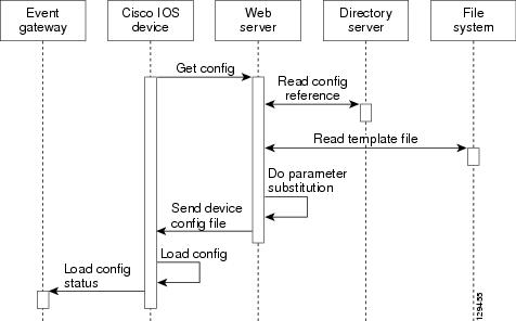
When the web server receives a request for a configuration file, it invokes the Java Servlet and executes the embedded code. This directs the web server to access the directory server and file system to read the configuration reference for this device and template. The configuration server prepares an instantiated configuration file by substituting all the parameter values specified in the template with valid values for this device. The configuration server forwards the configuration file to the web server for transmission to the Cisco IOS device.
The configuration agent at the router accepts the configuration file from the web server, performs XML parsing, syntax checking (optional), and loads the configuration file. The router reports the status of the configuration load as an event that can be subscribed to by a network monitoring or workflow application.
Load Initial Configuration
1. ![]() The Cisco Configuration Engine reads the template files.
The Cisco Configuration Engine reads the template files.
2. ![]() The Cisco Configuration Engine does the parameter substitution.
The Cisco Configuration Engine does the parameter substitution.
3. ![]() The Cisco Configuration Engine sends the device configuration to the Cisco IOS device.
The Cisco Configuration Engine sends the device configuration to the Cisco IOS device.
4. ![]() The Cisco IOS device tries to load the initial configuration.
The Cisco IOS device tries to load the initial configuration.
5. ![]() The Cisco IOS device publishes the load configuration status event to the event gateway.
The Cisco IOS device publishes the load configuration status event to the event gateway.
Modular Router
1. ![]() The modular router posts an HTTP request containing the hardware configuration to the Cisco Configuration Engine for the initial configuration.
The modular router posts an HTTP request containing the hardware configuration to the Cisco Configuration Engine for the initial configuration.
2. ![]() The Cisco Configuration Engine reads the hardware configuration of the device from the HTTP request and updates the directory server with the latest configuration.
The Cisco Configuration Engine reads the hardware configuration of the device from the HTTP request and updates the directory server with the latest configuration.
3. ![]() The Cisco Configuration Engine reads the template files.
The Cisco Configuration Engine reads the template files.
4. ![]() The Cisco Configuration Engine does the parameter substitution.
The Cisco Configuration Engine does the parameter substitution.
5. ![]() The Cisco Configuration Engine sends the device configuration to the Cisco IOS device.
The Cisco Configuration Engine sends the device configuration to the Cisco IOS device.
6. ![]() The modular router tries to load the initial configuration.
The modular router tries to load the initial configuration.
7. ![]() The modular router publishes the load configuration status event to the event gateway.
The modular router publishes the load configuration status event to the event gateway.
Load Partial Configuration
1. ![]() The user modifies a template in the Cisco Configuration Engine user interface.
The user modifies a template in the Cisco Configuration Engine user interface.
2. ![]() The template contents are passed to the Cisco Configuration Engine.
The template contents are passed to the Cisco Configuration Engine.
3. ![]() The Cisco Configuration Engine stores the template in the file system.
The Cisco Configuration Engine stores the template in the file system.
4. ![]() The user clicks the update device button in the user interface.
The user clicks the update device button in the user interface.
5. ![]() The Cisco Configuration Engine publishes a cisco.mgmt.cns.config.load event.
The Cisco Configuration Engine publishes a cisco.mgmt.cns.config.load event.
6. ![]() The Cisco IOS device receives the cisco.mgmt.cns.config.load event and in response to this event requests its configuration by contacting the server.
The Cisco IOS device receives the cisco.mgmt.cns.config.load event and in response to this event requests its configuration by contacting the server.
7. ![]() The Cisco Configuration Engine reads the template files.
The Cisco Configuration Engine reads the template files.
8. ![]() The Cisco Configuration Engine sends the device configuration to the Cisco IOS device.
The Cisco Configuration Engine sends the device configuration to the Cisco IOS device.
9. ![]() The Cisco IOS device tries to load the partial configuration.
The Cisco IOS device tries to load the partial configuration.
10. ![]() The Cisco IOS device publishes the load configuration status event to the event gateway.
The Cisco IOS device publishes the load configuration status event to the event gateway.
Modular Router
1. ![]() The user modifies a template in the Cisco Configuration Engine user interface.
The user modifies a template in the Cisco Configuration Engine user interface.
2. ![]() The template contents are passed to the Cisco Configuration Engine.
The template contents are passed to the Cisco Configuration Engine.
3. ![]() The Cisco Configuration Engine stores the template in the file system.
The Cisco Configuration Engine stores the template in the file system.
4. ![]() The user clicks the update device button in the user interface.
The user clicks the update device button in the user interface.
5. ![]() The Cisco Configuration Engine publishes a cisco.mgmt.cns.config.load event.
The Cisco Configuration Engine publishes a cisco.mgmt.cns.config.load event.
6. ![]() The modular router retrieves the cisco.mgmt.cns.config.load event and in response to this event requests its configuration by contacting the server.
The modular router retrieves the cisco.mgmt.cns.config.load event and in response to this event requests its configuration by contacting the server.
7. ![]() The Cisco IOS device posts a HTTP request containing the hardware configuration to the Cisco Configuration Engine for the partial configuration.
The Cisco IOS device posts a HTTP request containing the hardware configuration to the Cisco Configuration Engine for the partial configuration.
8. ![]() The Cisco Configuration Engine reads the hardware configuration of the device from the HTTP request and updates the directory server with the latest configuration.The Cisco Configuration Engine does the parameter substitution.
The Cisco Configuration Engine reads the hardware configuration of the device from the HTTP request and updates the directory server with the latest configuration.The Cisco Configuration Engine does the parameter substitution.
9. ![]() The Cisco Configuration Engine reads the template files.
The Cisco Configuration Engine reads the template files.
10. ![]() The Cisco Configuration Engine does the parameter substitution.
The Cisco Configuration Engine does the parameter substitution.
11. ![]() The Cisco Configuration Engine sends the device configuration to the modular router.
The Cisco Configuration Engine sends the device configuration to the modular router.
12. ![]() The modular router tries to load the partial configuration.
The modular router tries to load the partial configuration.
13. ![]() The modular router publishes the load configuration status event to the event gateway.
The modular router publishes the load configuration status event to the event gateway.
EventIDs and ConfigIDs
The Cisco Configuration Engine intersects two name space domains:
•![]() Configuration Domain
Configuration Domain
•![]() Event Domain
Event Domain
The Cisco Configuration Engine uses the Configuration Domain when a device communicates with the configuration server. It uses the Event Domain when a device communicates with the Cisco Configuration Engine using the publish and subscribe mechanism of the Integration Bus.
The device must be uniquely identified in these namespaces. The ConfigID uniquely identifies the device in the Configuration Domain. The EventID uniquely identifies the device in the Event Domain.
Because the Cisco Configuration Engine uses both the Integration Bus (event bus) and the configuration server to provide configurations to devices, both EventID and ConfigID must be defined for each configured Cisco IOS device.
The values for EventID and ConfigID for each device can be identical, or you can make them different when you add or edit device information using the user interface (see "Editing Devices" section on page 3-24).
Dynamic ConfigID and EventID Change Synchronization
The Cisco IOS, version 12.2.(11)T, was enhanced with new CLI ID commands that can modify the EventID and ConfigID, then reconnect the device to the Cisco Configuration Engine with the new IDs.
Common Log File Location
In Cisco Configuration Engine, all log files go into /var/log/CNSCE/<modulename>. For all Cisco Configuration Engine logs, this feature also includes custom logrotate scripts, located in the /etc/logrotate.d/cnsce directory.
Logrotate is a system utility that can rotate specified log files according to the conditions specified in a config file. There is a config file defined for each module (see "Sample Logrotate Config File" section). An Administrator-level user can make use of these config files to rotate logs of any module at any time.
For example, the command logrotate -f /etc/logrotate.d/cnsce/imgw rotates all IMGW logs and backs up all existing logs in the /var/log/CNSCE_ROTATED_LOGS directory. This is a common backup directory where all the rotated logs for all the modules are dumped.
Having a common directory allows you to set aside separate partition, or space, for backup logs.
Sample Logrotate Config File
#------------------------------------------------------------------
# Copyright (c) 2002, 2003, 2004 by Cisco Systems, Inc.
# All rights reserved.
#------------------------------------------------------------------
/var/log/CNSCE/imgw/* {
daily
missingok
copytruncate
compress
olddir /var/log/CNSCE_ROTATED_LOGS
}
Dynamic Log level Update
With this release, you can now change the log level programmatically using Web Services. A new API has been defined in Admin Web Service: setLogLevel(int level, Token token).
	/**
	* Changes the logging level of CE components.
	*
	* @param level, the logging level. Allowed values debug, info, warn, error
	*, fatal
	* @param token a Token object.
	* @return int, the new Log level.
	* @throws AdminServiceException if there is an error setting the log level.
	* @throws RemoteException if there is an error communicating with the service.
	*/
int setLogLevel(int level, Token token)
throws AdminServiceException, RemoteException ;
For debug, set level =1.
For info, set level =2.
For warn, set level =3.
For error, set level =4.
For fatal, set level =5.
Monitoring Service
A wrapper monitoring service is provided in this release to monitor the various Cisco Configuration Engine services. If any of the Cisco Configuration Engine processes die, the monitoring service exits.
Other applications can monitor this single Cisco Configuration Engine process, rather than all dependent Cisco Configuration Engine services. In the case of failure, they can take appropriate action, such as invoking the restart script.
Other applications can check for the existence of this wrapper monitoring process to make sure that all Cisco Configuration Engine services are up. If the process is not running, it will signify that one or more of Cisco Configuration Engine services are down.
This service report the health of the various Cisco Configuration Engine processes in a log file. If there is a failure, the service reports the error and exits. A time stamp is appended to each report.
There is a provision to start, stop, or check the status of this service. The following Cisco Configuration Engine processes are monitored:
•![]() HTTP/Tomcat
HTTP/Tomcat
•![]() Event Gateway
Event Gateway
•![]() IMGW
IMGW
•![]() Web Services
Web Services
•![]() Tibco Rendezvous Daemon
Tibco Rendezvous Daemon
Health Checking Utility
A wrapper resource health checking utility is provided in release 3.5 to monitor the health of the Event Gateways and Tibco Rendezvous Daemon. If any of the processes stops, the health checking utility restarts the process and logs a message in /var/log/CNSCE/ce_resource/ce_resource.log file. This utility (resource_monitor_daemon) starts during the Cisco Configuration Engine setup and stops when the Cisco Configuration Engine server stops.
Software Architecture
The monitoring service is a single process running as a daemon on the Cisco Configuration Engine host system. This daemon checks the state of various Cisco Configuration Engine processes at regular interval of time. This time interval is configurable. If any of the process in Cisco Configuration Engine dies, the daemon exits. A shell script is provided to start, stop, or check the status of this daemon. Applications can check the Cisco Configuration Engine health using this shell script.
Daemon Start/Stop script
The MonitorCE shell script starts and stops the daemon. This script also provides the status of the daemon script. Integrating applications use this shell script to monitor the state of Cisco Configuration Engine services.
This script is registered as a start up script on the local OS using the chkconfig utility. In this way, the script is started automatically after the host system is restarted. The script is located in the /etc/rc.d/init.d directory.
Logging
The daemon checks for the health of each Cisco Configuration Engine process and reports it in a log file. The log files are located in /var/log/CNSCE/ce_health/ce_monitor.log. A time stamp is appended with each report.
Here is an example of the log file:
07/14/2005-06:53 HTTP/Tomcat is UP in plain-text mode.
07/14/2005-06:53 HTTP/Tomcat is UP in ssl mode.
07/14/2005-06:53 Event Gateway (plaintext operation) at port 11011 is UP.
07/14/2005-06:53 Event Gateway (plaintext operation) at port 11013 is UP.
07/14/2005-06:53 Event Gateway (plaintext operation) at port 11015 is UP.
07/14/2005-06:53 Event Gateway (plaintext operation) at port 11017 is UP.
07/14/2005-06:53 Event Gateway (crypto operation) at port 11012 is UP.
07/14/2005-06:53 Event Gateway (crypto operation) at port 11014 is UP.
07/14/2005-06:53 Event Gateway (crypto operation) at port 11016 is UP.
07/14/2005-06:53 IMGW is UP.
07/14/2005-06:53 Cisco-CE Event Bus is UP.
07/14/2005-06:53 CEAdminService web service is UP in plain-text mode.
07/14/2005-06:53 CEConfigService web service is UP in plain-text mode.
07/14/2005-06:53 CEImageService web service is UP in plain-text mode.
07/14/2005-06:53 CEExecService web service is UP in plain-text mode.
When HTTP is Down
Here is an example when HTTP is down:
07/14/2005-06:53 HTTP/Tomcat is DOWN in plain-text mode.
HTTP GET failed on URL http://infystorm5:80/cns/Config
Connection refused
07/14/2005-06:53 HTTP/Tomcat is DOWN in ssl mode.
HTTP GET failed on URL https://infystorm5:444/cns/Config
Connection refused
07/14/2005-06:53 Event Gateway (plaintext operation) at port 11011 is UP.
07/14/2005-06:53 Event Gateway (plaintext operation) at port 11013 is UP.
07/14/2005-06:53 Event Gateway (plaintext operation) at port 11015 is UP.
07/14/2005-06:53 Event Gateway (plaintext operation) at port 11017 is UP.
07/14/2005-06:53 Event Gateway (crypto operation) at port 11012 is UP.
07/14/2005-06:53 Event Gateway (crypto operation) at port 11014 is UP.
07/14/2005-06:53 Event Gateway (crypto operation) at port 11016 is UP.
07/14/2005-06:53 IMGW is UP.
07/14/2005-06:53 Cisco-CE Event Bus is UP.
07/14/2005-06:53 CEAdminService web service is DOWN in plain-text mode.
HTTP GET failed on URL http://infystorm5:80/cns/services/CEAdminService?wsdl
Connection refused
07/14/2005-06:53 CEConfigService web service is DOWN in plain-text mode.
HTTP GET failed on URL http://infystorm5:80/cns/services/CEConfigService?wsdl
Connection refused
07/14/2005-06:53 CEImageService web service is DOWN in plain-text mode.
HTTP GET failed on URL http://infystorm5:80/cns/services/CEImageService?wsdl
Connection refused
07/14/2005-06:53 CEExecService web service is DOWN in plain-text mode.
HTTP GET failed on URL http://infystorm5:80/cns/services/CEExecService?wsdl
Connection refused
07/14/2005-06:54 Exiting the CE-Health Beep Daemon.
Also, a configuration file (/etc/logrotate.d/cnsce/ce_health) is provided to rotate the above log file.
End User Interface
You can start, stop, and check the status of the daemon using the script called MonitorCE. This script is located in /etc/rc.d/init.d. To know the status of Cisco Configuration Engine services, integrating applications have to issue the command:
/etc/rc.d/init.d/MonitorCE status
Usage
MonitorCE {start|stop|restart|reload|status}
•![]() start - starts MonitorCE service. If MonitorCE service is already started, it does nothing.
start - starts MonitorCE service. If MonitorCE service is already started, it does nothing.
•![]() stop - stops MonitorCE service.
stop - stops MonitorCE service.
•![]() restart - first stops the service, and then starts it again.
restart - first stops the service, and then starts it again.
•![]() reload - first stops the service, and then starts it again.
reload - first stops the service, and then starts it again.
•![]() status - tells if the service is up or not.
status - tells if the service is up or not.
User Authentication
The Cisco Configuration Engine can authenticate a user by using the external authentication application. When a user logs into the Cisco Configuration Engine, instead of authenticating the user by using the Cisco Configuration Engine LDAP server, the Cisco Configuration Engine forwards the authentication request to an external authentication application. The Cisco Configuration Engine can support LDAP based authentication and integrate with the Microsoft Active Directory.
The Cisco Configuration Engine can authenticate the user both internally and externally based on the user selection during the Cisco Configuration Engine setup.
During the Cisco Configuration Engine setup, the administrator can select the authentication mode. The Cisco Configuration Engine prompts for IP address and user credentials for the remote LDAP server.
Choose the authentication mode of the system: 0=internal mode, 1=external mode.
This example shows how to set the external authentication settings.
Enter IP Address of external directory server: 10.1.2.3
Enter port number of external directory server: [389]
Enter prefix for user name in external directory server: [cn]
Enter suffix for user name in external directory server: o=myorg,c=us
Also, the user can enable or disable the authorization.
This example shows how to set the external authorization settings:
Do you want to enable authorization? (y/n) [n] y
Enter UserDN for external directory server: cn=simpleuser,o=myorg,c=us
Enter password for the above user: *****
Re-enter password for the above user: *****
Enter role attribute name in user objectclass which defines the role: description
Enter role attribute value which defines the role of an administrator: administrator
Authorization
The Cisco Configuration Engine does not support task or resource-based authorization. However, the Cisco Configuration Engine GUI have Admin and Operator user levels. Depending on the role of the user, the appropriate GUI screens are displayed to the user. For more information about level of access, see Chapter 2, "Levels of Access".
Backup Authentication-Authorization
To support existing the Cisco Configuration Engine users, backup authentication and authorization is supported for the external authentication mechanism. The Cisco Configuration Engine user who logs in is authenticated against the external application. If the external authentication fails, the user is authenticated against the Cisco Configuration Engine LDAP Server. The fall-back server will be the LDAP directory used by Cisco Configuration Engine (internal or external). If the user chooses internal authentication, Cisco Configuration Engine LDAP is used for authentication and there will be no fall-back authentication server used.
Multizone System Setup
The installation of the Cisco Configuration Engine software does not offer the multizone system setup by default. If you require a multizone system setup, you must enable the multizone feature during the system setup. To setup multiple IP addresses on the Cisco Configuration Engine server, you must manually customize the network parameters of the server to have multiple IP addresses. Multiple IP addresses can be configured by using IP aliasing on the network interface card. For more information see Chapter 6, "Setting Up a Multizone System" in Cisco Configuration Engine Installation and Configuration Guide.
 Feedback