
Table Of Contents
Expanded View of Network Elements
Using the Network Topology Menus
Service Class Template Manager
Network Topology
The CWM Network Topology application is a Java-based application that is launched from the CWM desktop. The CWM topology subsystem has been redesigned in Release 11 of CWM to provide more efficient navigation, modularity and scalability. New processes within the topology server handle different types of network discovery, and individual clients have a direct connection to the topology server for their respective topologies.
The CWM Network Topology for Release 11 of CWM is divided into three windows: the small window in the upper left hand corner of the Network Topology main window presents an overview of the network; the window in the lower left hand corner of the Network Topology provides for Integrated, AutoRoute or Standalone network views; and the center window provides a view of the network as it's automatically presented when the Network Topology main window first appears. Release 11 of CWM also displays a rectangular shaped navigational feature in the overview window, called a Panner, that allows resizing, zooming and panning. Resizing and moving this rectangle with the mouse pointer will be reflected in the representation of the overall view.
Tabs found at the bottom of the Network Topology main window provide Integrated, Auto Route and Standalone views of the network. The network is automatically discovered and presented through these topology map windows. Network element and trunk status are represented by icon color changes dynamically. Custom background images can be associated with each network map to provide a user-defined view of the network.
Network Topology Main Window
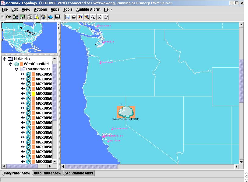
Figure 3-1 shows the CWM Network Topology's main window in its default Integrated View. Other views include Auto Route and Standalone, which can be accessed by selecting the tabs found at the bottom of this window. All Network Topology views contain the following components:
•
Title bar—displays the hostname of the CWM server (also known as the topology gateway) to which a given instance of network topology is connected.
•
•
•
•
•
Figure 3-1 Network Topology Main Window—Integrated View
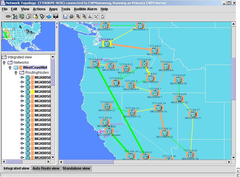
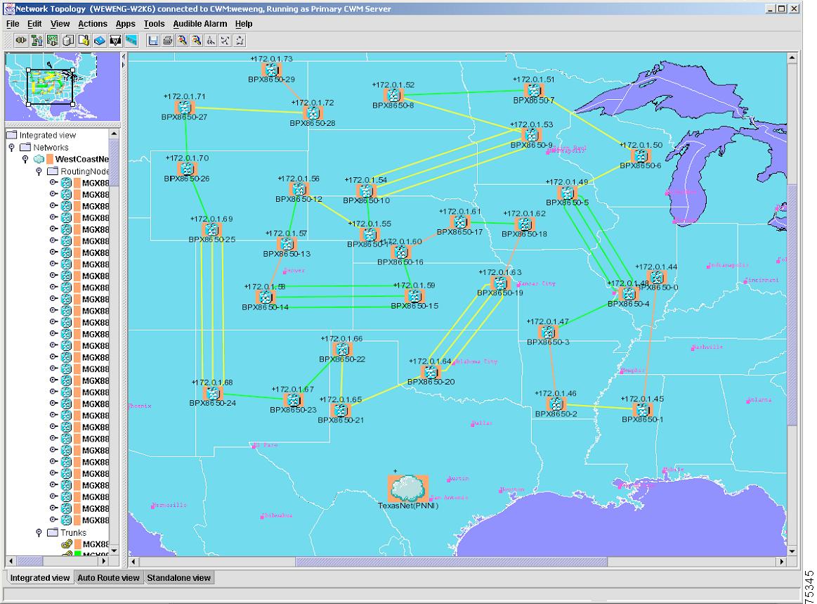
Figure 3-2 shows the Auto Route view of the CWM Network Topology which is accessed by selecting the Auto Route tab found at the bottom of this window.
Figure 3-2 Network Topology Main Window—Auto Route View
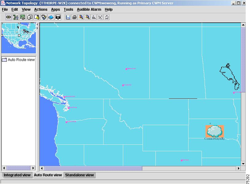
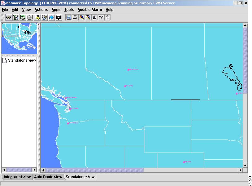
Figure 3-3 shows the Standalone view of the CWM Network Topology which is accessed by selecting the Standalone tab found at the bottom of this window.
Figure 3-3 Network Topology Main Window—Standalone View
Expanded View of Network Elements
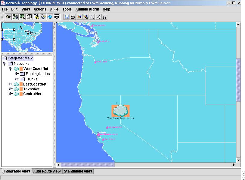
Click on the folder node to the left of a network in order to view its network elements. Figure 3-4 shows an expanded view of network routing nodes and trunks contained in the left panel of the Network Topology's main window.
Figure 3-4 Expanded View—Network Routing Nodes and Trunks
Click on the folder node to the left of a network's elements in order to see an expanded view of the network element you have chosen. Figure 3-5 shows an expanded view of a network's routing nodes.
Figure 3-5 Expanded View—Routing Nodes
Title Bar
The title bar displays the hostname of the CWM server and tells whether the CWM workstation is a Primary CWM, Secondary CWM or Tertiary CWM.
Menu Bar
The network topology menu bar allows you to make a selection by pulling down a menu and clicking on a desired action. The following are available:
•
•
•
•
•
•
•
•
Left click on the menu to view the available options. Scroll to the selected option and release the mouse button to select a menu item. Additionally, keyboard shortcuts (accelerators) and mnemonics are also provided to directly launch a menu selection.
The available menu options are discussed in detail later in this chapter.
Tool Bar
The network topology toolbar replaces the desktop of previous releases of CWM and Cisco StrataView Plus. The network topology toolbar provides icons that enable you to launch the more frequently used functions of CWM. The following CWM applications, (discussed in detail later in this chapter), are launched by clicking on the appropriate icon:
•
•
•
•
•
•
•
•
•
•
The following functions are also available on the network topology tool bar:
•
•
•
•
•
•
•
The network topology tool bar is a dockable tool bar. You can separate the toolbar from the network topology main window or position it vertically instead of horizontally. To separate the tool bar, left click the mouse in the tool bar position handler and drag the tool bar to the desktop location you prefer.
Hierarchy Tree
Displays network information in hierarchy tree format by clicking on the folder node that is found to the left of the network element you want to view. By default, the Integrated View is displayed when the Network Topology main window first appears, and a folder node sits to the left of a folder called Networks. By clicking on the folder node, all networks will be displayed under the networks folder; click on the folder node to the left of a displayed network to view additional network elements including routing nodes, trunks and XLMI links.
Tabs
Tabs found at the bottom of the Network Topology main window provide different topology views of the network based on the type of presentation desired. Release 11 of CWM provides three views: Integrated View, Auto Route View and Standalone View.
Status Bar
Displays any errors or informational messages as you attempt to perform various actions.
Panner
Release 11 of the Network Topology's overview window manages a reduced version of the overall view which may be displayed in a small window beside the display of the main view. The overview is a periodically generated bitmap of the main view.
The overview also displays a rectangular shaped navigational feature called a Panner that allows resizing, zooming and panning. Resizing and moving this rectangle with the mouse pointer will be reflected in the representation of the overall view. The Network Topology's main view is zoomed in or zoomed out by using the Panner, and it is scrolled when the position of the Panner has been changed.
Using the Network Topology Menus
This section describes the functions provided via the network topology menus.
File Menu
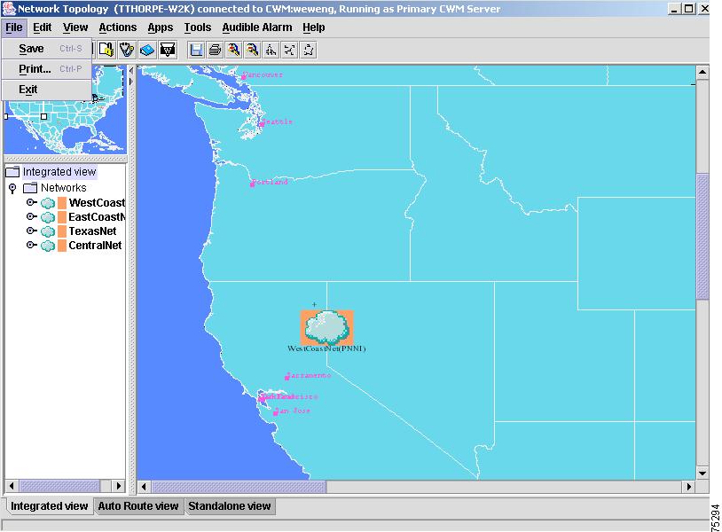
The File menu, shown in Figure 3-6, provides network topology application level operations:

Note
Figure 3-6 File Menu Options
Save
The Save option saves the current positions of the nodes, trunks, and group information in all of the views. Also, the current map, view size and view zoom level are all saved to the user.home directory. These files will be parsed the next time the Network Topology is launched.
The Print option prints the current view of the topology main window.
Exit
The Exit option exits the network topology application and closes the main window.
Note
Edit Menu
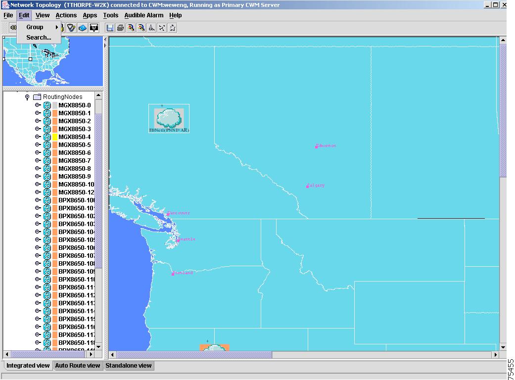
The Edit menu, shown in Figure 3-7, provides editing access to network topology information using a Group submenu.
Figure 3-7 Edit Menu Options
Group
Group submenu options are used to create or delete a node or group of nodes. Drag your curser over the Network Topology map selecting all nodes that you want contained in a group. Then select the Group submenu option from the Edit dropdown menu in order to create a group. The Add Node option, shown in Figure 3-8, is used to add a node or a group of nodes; the Delete Node and Delete options, shown in Figure 3-11, are used to delete a node or a group of nodes.
Note
Add Node
Selecting the Add Node option displays a dialog box into which you provide the required information for a node to be added to the network.
Note
In order to add a node, you must first choose a node from the left panel of the Network Topology's main window by single clicking on the node to highlight it, and then selecting Add Node from the Group submenu, Edit dropdown menu, as shown in Figure 3-8.
Figure 3-8 Group Submenu Option—Add Node
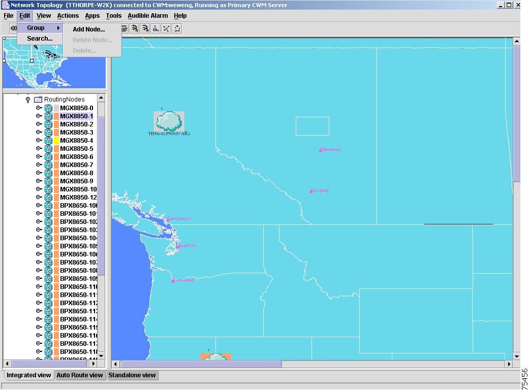
Figure 3-9 shows the Group Add Node dialog window that appears after selecting Add Node from the Group submenu. Use this window to add required information for a node that will be added to the network.
Figure 3-9 Group Add Node Dialog Window
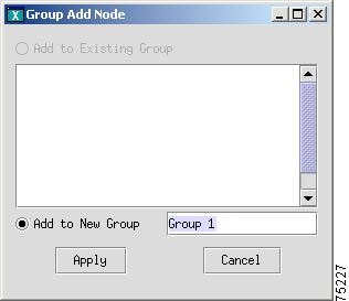
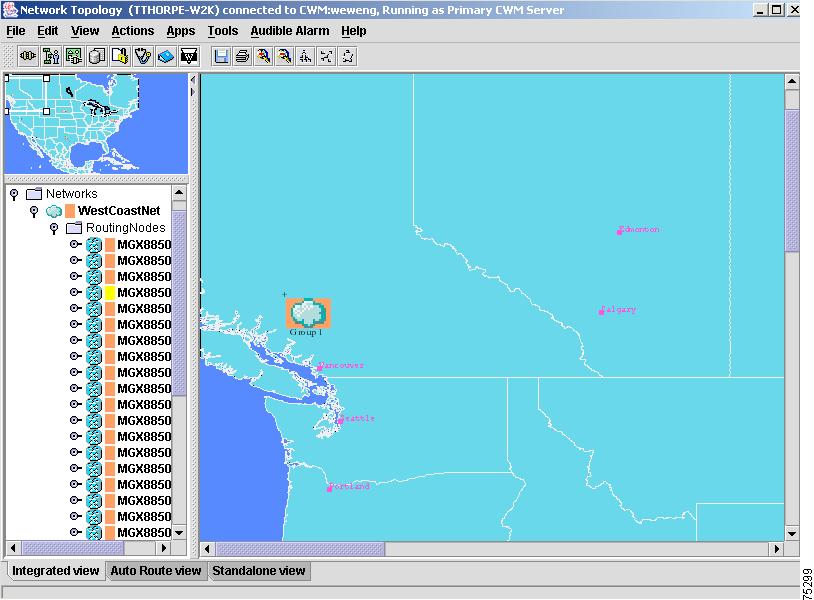
Figure 3-10 shows the successful addition of the Group 1 node.
Figure 3-10 Node Successfully Added
In order to delete a node, you must first choose the node from the Network Topology map by single clicking on the node to highlight it, and then selecting Delete Node from the Group submenu, as shown in Figure 3-11. The Delete option, described below, allows you to delete a group of nodes.
Delete Node
Selecting the Delete Node option displays a dialog box into which you provide the required information to delete a node from the network.
Delete
Selecting the Delete option displays a dialog box into which you provide the required information to delete a group of nodes from the network.
Figure 3-11 Delete Node Submenu
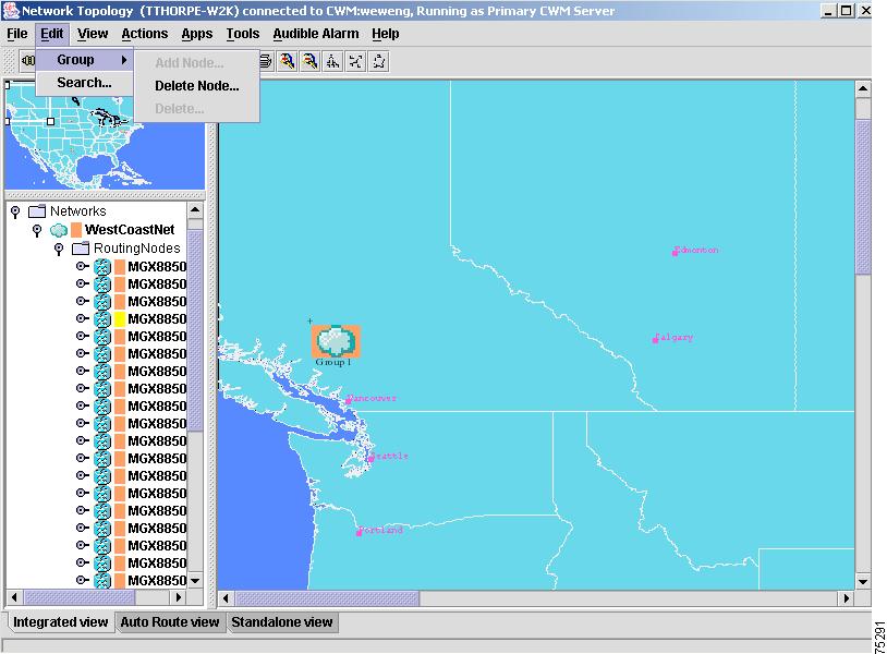
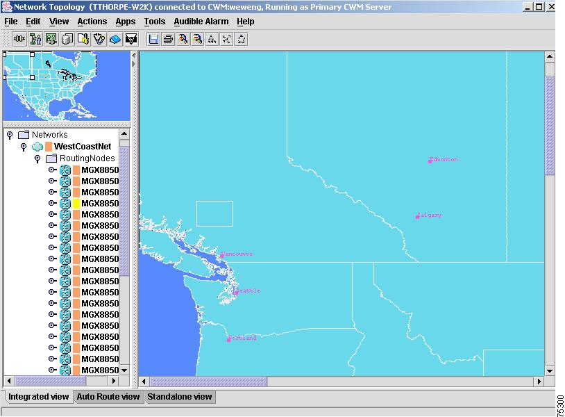
Figure 3-12 shows the successful deletion of the Group 1 node.
Figure 3-12 Node Successfully Deleted
Although the Delete submenu option is used to delete a group of nodes from the network, it can also be used to delete one node. Highlight the node you want to delete in the left panel of the Network Topology's main window, and then select the Delete submenu (or Delete Node submenu) from the Group menu.
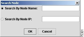
Select Search from the Edit dropdown menu to search for a node using the Search Node dialog window, as shown in Figure 3-13. This dialog window allows you to search for a node using the node name or node IP address.
Figure 3-13 Search Node Dialog Window
Note
View Menu
The View menu provides the following options which directly change the current view of network topology:
•
•
•
•
•
Note
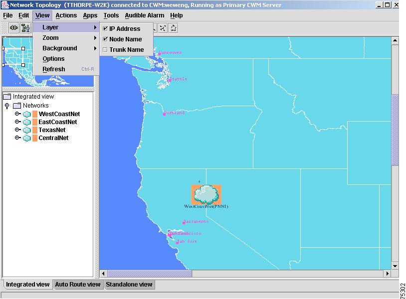
Layer
The Layer submenu option, shown in Figure 3-14, allows the user to turn on or off the display for the IP Address, Node Name and Trunk Name.
Figure 3-14 View Menu Options—Layer Submenu Options
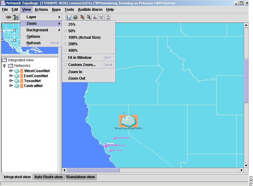
Zoom
The Zoom submenu option, shown in Figure 3-15, provides different levels of zoom functions for resizing the view of the Network Topology window.
Figure 3-15 Zoom Submenu Options
Note
Zoom (Percentage)
The Zoom option zooms the current submap, or window, by the percentage you choose:
•
•
•
•
•
Fit in Window
The Fit in Window option fits all objects in the current submap into the available space on the submap.
Custom Zoom
The Custom Zoom option displays a dialog box allowing you to provide a specific percentage to zoom the current submap.
Zoom In / Zoom Out
The Zoom In/ Zoom Out option zooms in or zooms out of the current submap image.
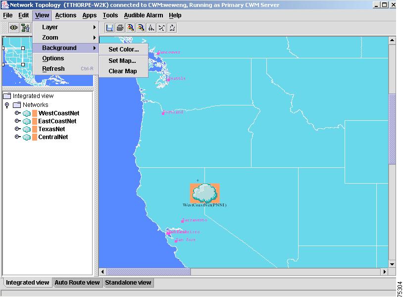
Background
Figure 3-16 shows the Background submenu options which allow you to change the color or map view of the Network Topology window.
Figure 3-16 Background Submenu Options
Set Color
The Set Color option for Release 11 of CWM provides a Set Background Color in Map dialog window containing three tabbed views that allow you different ways to select or clear the background color of the current view. These color setting options are shown in Figure 3-17, Figure 3-18 and Figure 3-19.
Figure 3-17 shows the default window, Swatches, that appears when the application is first launched. The Swatches window provides swatches of color from which you can select. Click on a color and a preview sample of your selection appears in the lower half of the window. Click on the OK button to apply the new colors; select Reset to start over; select Cancel to exit this window.
Figure 3-17 Set Background Color in Map—Swatches Window
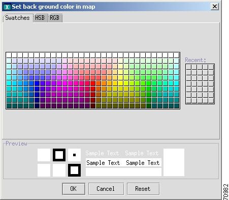
Figure 3-18 shows the next window in this application called HSB. The HSB window provides a similar selection of colors as the swatches window, however a color bar has been provided on the right side of the color window to assist you in selecting HSB and RGB with greater precision. Click on a color and a preview sample of your selection appears in the lower half of the window. Click on the OK button to apply the new colors; select Reset to start over; select Cancel to exit this window.
Figure 3-18 Set Background Color in Map—HSB Window
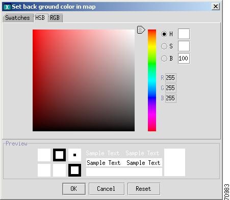
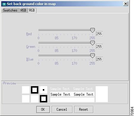
Figure 3-19 shows the final window in this application called RGB. The RGB window provides Red, Green and Blue color intensity scroll bars to assist you in more accurately measuring the amount of each of these colors that will be used as background color. Use the scroll bars to select a color range and a preview sample of your selection appears in the lower half of the window. Click on the OK button to apply the new colors; select Reset to start over; select Cancel to exit this window.
Figure 3-19 Set Background Color in Map—RGB Window
Set Map
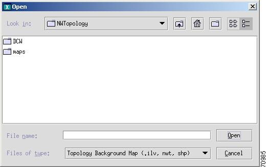
The Set Map option for Release 11 of CWM provides a directory of maps with a variety of ILV images from which to select and save Topology backgrounds. Figure 3-20 shows a directory of images that appear after selecting Set Map from the Background menu option. Double click on a folder to view the map images contained in the folder, and then click on an image to select it; click on the Open button to open the image.
Note
Figure 3-20 Set Map Window
Clear Map
The Clear Map option for Release 11 of CWM can be used to clear the background map.
Options
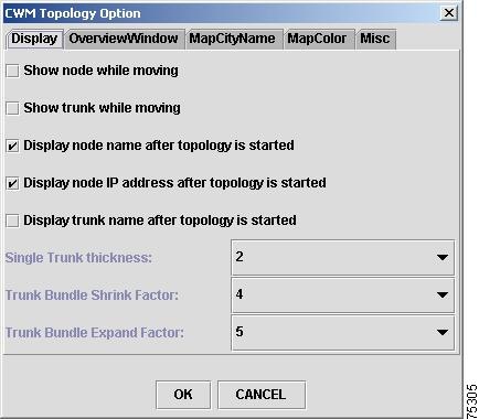
The View menu's Options submenu brings up a CWM Topology Option dialog window, as shown in Figure 3-21. This dialog window contains tabbed windows that allow you to change the display of the Network Topology elements using Display, Overview Window, Map City Name, Map Color and Miscellaneous. The default Display window, shown in Figure 3-21, allows you to choose from the following:
•
•
•
•
•
You can also set the single trunk thickness from 1 to 10; the trunk bundle shrink factor can be set from 1 to10; and the trunk bundle expand factor can be set from 1 to 20.
Note
Figure 3-21 Display Window
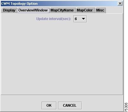
The Overview Window, shown Figure 3-22, allows you to set the update interval within a range of 1 to10 seconds.
Figure 3-22 Overview Window
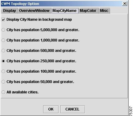
The Map City Name window, shown in Figure 3-23, allows you to change the display of the Network Topology using the following options:
•
•
•
•
•
•
•
•
Figure 3-23 Map City Name Window
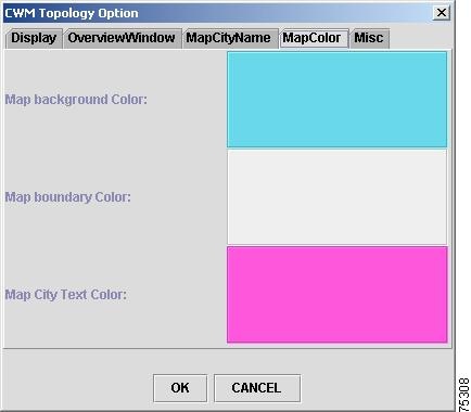
The Map Color window, shown in Figure 3-24, allows you to change the color display of the Network Topology using the following:
•
•
•
Double click on any of the color swatches to select a color.
Figure 3-24 Map Color Window
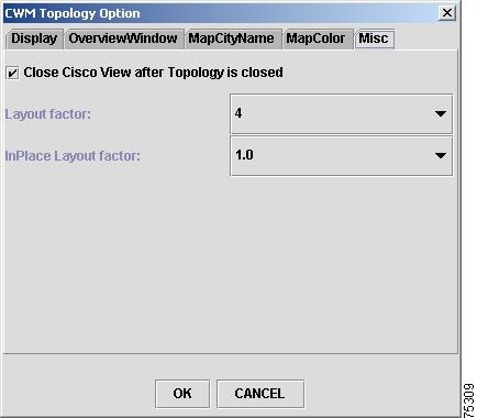
The Miscellaneous window, shown in Figure 3-25, allows you the following miscellaneous options:
•
•
•
Figure 3-25 Miscellaneous Window
Refresh
The View menu offers a Refresh submenu option that can be used to refresh the current Network Topology view(s).
Actions Menu
The Actions menu, shown in Figure 3-26, provides the following options:
•
•
•
•
Note
Figure 3-26 Actions Menu Options
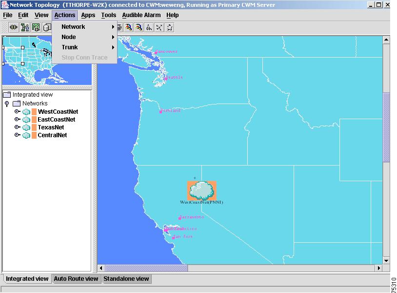
Figure 3-27 shows the Network submenu options.
Figure 3-27 Network Submenu Options
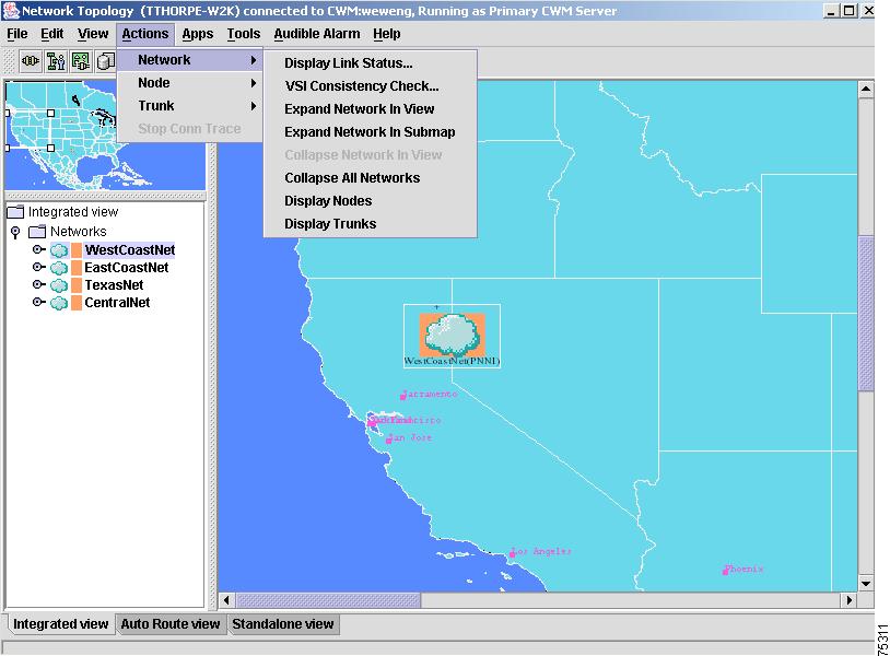
Network
The Network submenu option enables the display of the following views:
Display Link Status
The Display Link Status option displays the link status of all nodes in the current submap.
Note
VSI Consistency Check
The VSI Consistency Check option brings up a Display VSI Resource Check dialog box which lists errors and VSI trunk end partition information.
Note
Expand Network In View
To see an expanded view of the network, first highlight the network you would like to view by placing the curser on the network in the CWM Topology window, and then select the Expand Network In View option from the Network submenu. You will then see an expanded view of the network in the Network Topology main window.
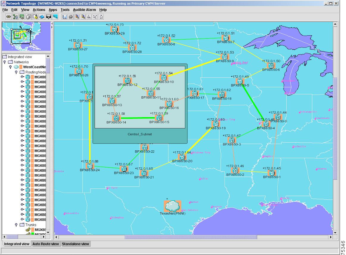
Expand Network In Submap
To see an expanded view of the network in a submap, first highlight the network you would like to view by placing the curser on the network in the CWM Topology window, and then select the Expand Network In Submap option from the Network submenu. You will then see a new window which displays the selected network in the current submap.
Collapse Network In View
The Collapse Network In View option shows a collapsed view of the selected node in the Network Topology main window.
Collapse All Networks
The Collapse All Networks option shows a collapsed view of the entire network in the Network Topology main window.
Display Nodes
The Display Nodes option displays all nodes for the selected network.
Display Trunks
The Display Trunks option displays all trunks for the selected network.
Figure 3-28 shows the Expand Network In View submenu option.
Figure 3-28 Expand Network In View Submenu Option
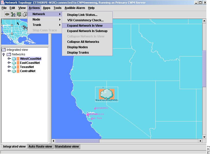
Figure 3-29 shows an expanded view of the network after the Expand Network In View submenu option has been selected.
Figure 3-29 Expanded View of Network
Figure 3-30 shows the Collapse All Networks submenu option.
Figure 3-30 Collapse All Networks Submenu Option
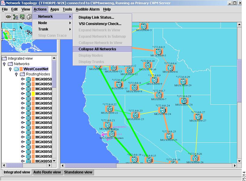
Figure 3-31 shows a collapsed view of the network after the Collapse All Networks submenu option has been selected.
Figure 3-31 Collapsed Networks

Figure 3-32 shows the Expand Network in Submap submenu option.
Figure 3-32 Expand Network in Submap Submenu Option
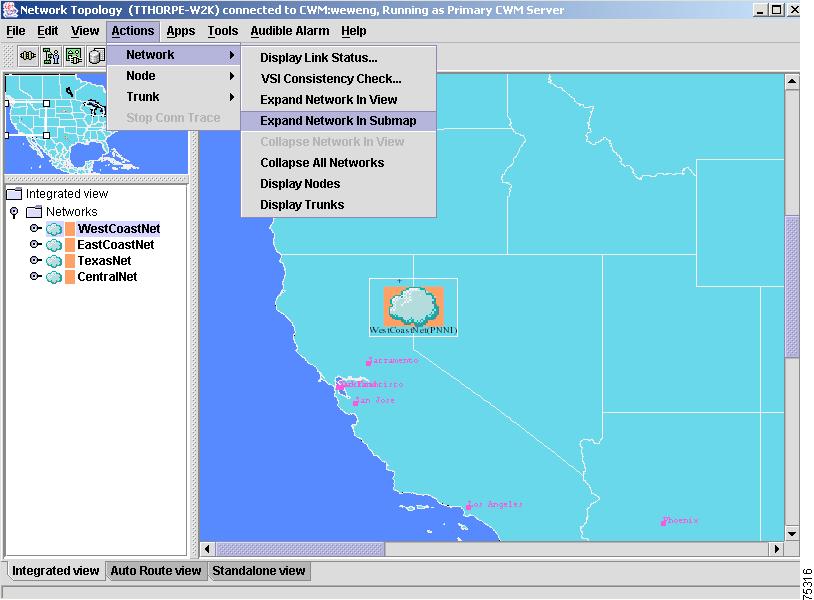
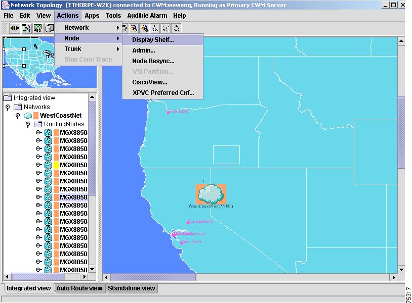
Figure 3-33 shows the Node submenu with the Display Shelf submenu option selected.
Figure 3-33 Node Submenu—Display Shelf Submenu Option
Node
The Node submenu option brings up a dialog window for operations specific to a selected node:
Display Shelf
The Display Shelf option brings up a dialog window that shows the shelves of a selected node. Select a node from the left panel of the Network Topology's main window, and then select the Display Shelf submenu option in order to launch the Display Shelf dialog window shown in Figure 3-34:
Figure 3-34 Display Shelf Dialog Window
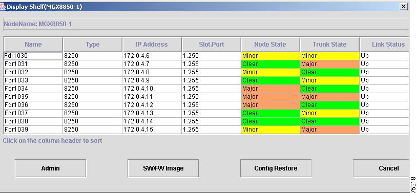
Use the Display Shelf dialog window to view the selected node's name, node type, IP address, slot and port location, node state, trunk state and link status.
Admin
The Admin option displays a telnet session window to connect to the selected node in the current submap.
Node Resync
The Node Resync option displays the Node Resync Progress window for the selected node in the current submap. Figure 3-35 shows the Node submenu with the Node Resync submenu option selected.
Figure 3-35 Node Submenu—Node Resync Submenu Option
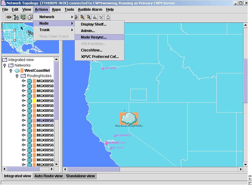
Figure 3-36 shows the Node Resync dialog window which is displayed after selecting Node Resync from the Node submenu.
Figure 3-36 Node Resync Dialog Window
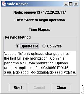
Click on the Start button in the Node Resync dialog window in order to begin the node re-syncing process.
VSI Partition
The VSI Partition option displays the VSI Partition dialog box for the selected node in the current submap.
Cisco View
The CiscoView option that is accessed from the Node submenu (versus the Cisco View option that is accessed using the Apps pull-down menu, as described in this chapter under "Apps Menu"), brings up a CiscoView window that allows you to select a device for a particular node in which to view Telnet, CCO, Cisco Support, Preferences, About, and Help information.
The recommended values to set for SNMP preferences in Cisco View are as follows:
•
•
•
Complete the following steps in order to over subscribe a port on the MGX 8850 switch:
Step 1
Step 2
Step 3
Step 4
Once the channels window appears, you will see a list of connections for that card. The fifth column of this window will show the DLCI information for each connection that is listed.
Step 5
Step 6

Tips
XPVC Preferred Cnf
XPVC Preferred Cnf is a tool that allows users to add, modify or delete data to or from the xpvc_Pref table. If there is no entry, then no provisioning can be done. This xpvc_preferred data is used by Connection Manager and the Proxy subsystem for the provisioning of XPVCs.
The XPVC Preferred Cnf option brings up the XPVC Table Configurator dialog window with XPVC Preferred data displayed as Active Entries (contains all of the current Active entries in the xpvc_preferred table) or Inactive Entries.
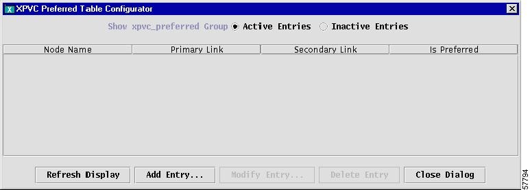
Figure 3-37 shows the XPVC Preferred Table Configurator window that appears after selecting the XPVC Preferred Cnf option from the Node submenu.
Figure 3-37 XPVC Preferred Table Configurator
Note
The XPVC Preferred Table Configurator window lists nodes by Node Name, with Primary Link and Secondary Link information presented in neighboring rows. The Is Preferred column shows whether an XPVC connection is or is not preferred.
Refresh Display, Add Entry, Modify Entry, and Delete Entry options are found at the bottom of the XPVC Preferred Cnf dialog box and are used against the xpvc_preferred table. The protocol type is automatically assigned as XPVC, provided that all user endpoints that are selected in the AR network have a xpvc_preferred table entry with the preferred flag set.
Note
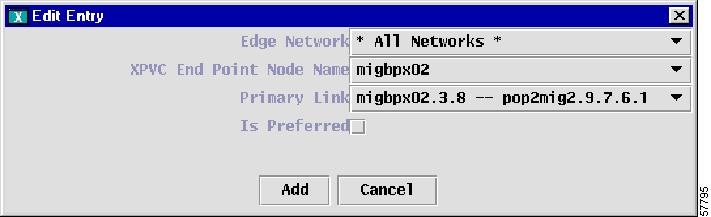
Figure 3-38 shows the XPVC Edit Entry window that appears after pressing the Modify Entry button on the XPVC preferred Table Configurator window. The XPVC Edit Entry window allows you to make specific modifications to an XPVC.
Figure 3-38 XPVC Edit Entry
Trunk
The Trunk submenu option provides information about an individual trunk. Figure 3-39 shows the Display Trunk option which is located under the Actions menu.
Figure 3-39 Trunk Submenu—Display Trunk Submenu Option
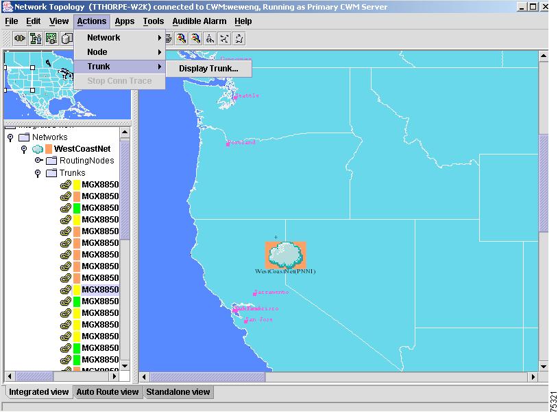
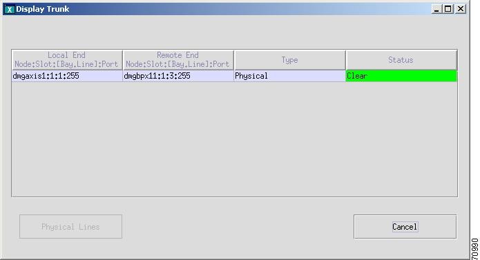
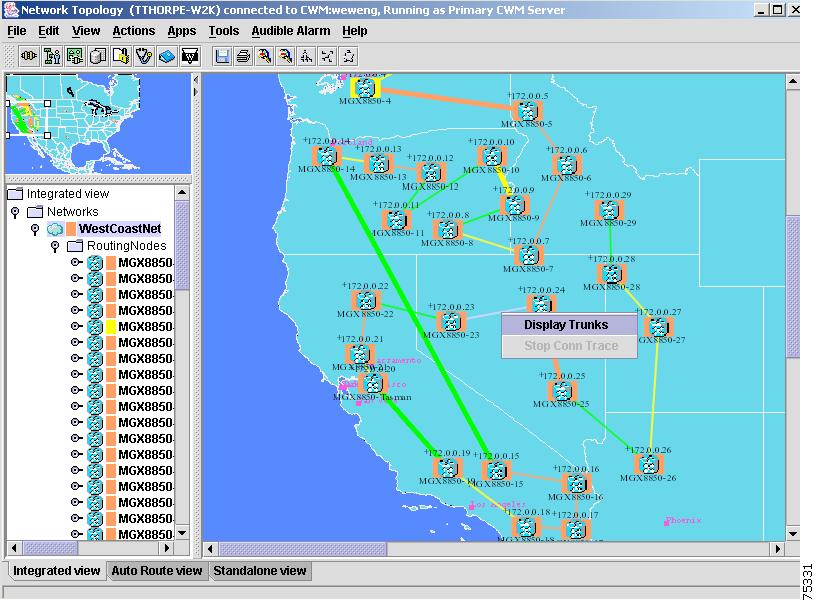
Display Trunk
Figure 3-40 shows the Display Trunk window. To view information about a trunk in the current submap, first select a trunk from the list of network elements contained in the lower left hand window of the Network Topology main window. Next, select Actions, then Trunk, and then Display Trunk to invoke the Display Trunk dialog window. This window contains information about the selected trunk including local end (Node:Slot:[Bay.Line]:Port), remote end (Node:Slot:[Bay.Line]:Port), trunk type and trunk status.
Figure 3-40 Actions Menu—Display Trunk Window
Stop Connection Trace
CWM Connection Trace is initiated from the CWM Connection Manager application. The Stop Conn Trace submenu option that is found under the Network Topology's Actions menu allows you to stop a connection trace that is currently in progress.
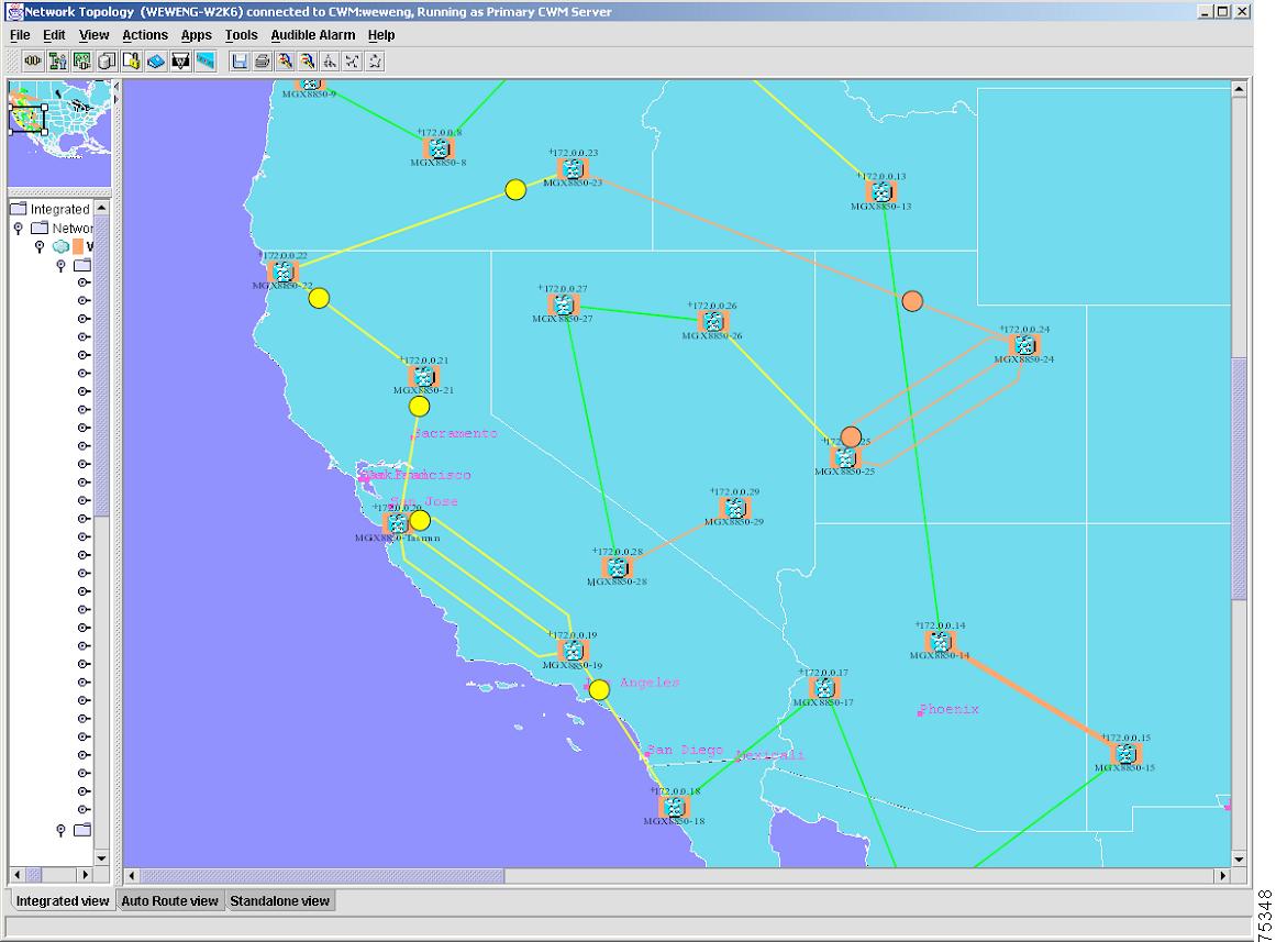
Traffic flow through the network is represented by rotating circles that move in the direction of the network traffic, as shown in Figure 3-41. Traffic flow is not visible unless Connection Trace has been initiated on a connection using the CWM Connection Manager.
Figure 3-41 Connection Trace
Note
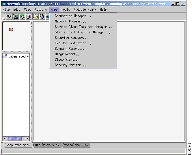
Apps Menu
The Apps menu, shown in Figure 3-42, provides applications that are launched from the main window of the CWM Network Topology, but are external to the network topology application.
Figure 3-42 Apps Menu Options
Connection Manager
The Connection Manager option launches the Connection Manager (CM) application. The CM provides the network manager the ability to add, modify, and delete end-to-end connections. See Chapter 4 for additional information about this application.
Network Browser
The Network Browser option launches the Network Browser application. The Network Browser displays network elements based on either a physical or logical relationship among the various network elements.See Chapter 5 for additional information about this application.
Service Class Template Manager
The Service Class Template Manager option launches the Service Class Template Manager (SCT) application. The SCT allows for creating SCT files which can be loaded to nodes, and associated with interfaces on cards within these nodes. See Chapter 7 for additional information about this application.
Statistics Collection Manager
The Statistics Collection Manager option launches the Statistics Collection Manager (SCM) application. The SCM provides a forms-based interface to establish and modify statistic collection policies for the network. See Chapter 8 for additional information about this application.
Security Manager
The Security Manager option launches the Security Manager application. The Security Manager provides controlled access to multiple users of CWM based on the unique user ID and password. See Chapter 6 for additional information about this application.
CWM Administration
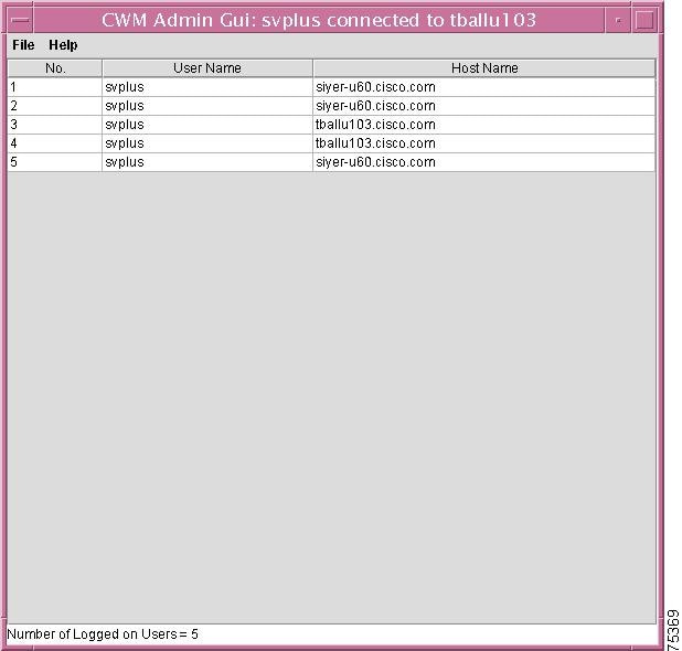
The CWM Administration graphical user interface (GUI), shown in Figure 3-43, is used to monitor the number of users accessing the CWM Desktop at any one time. The CWM Administration feature has the following functions:
•
•
This information is updated dynamically on the GUI, with new users logging in and existing users logging out of the GUI sessions.
Figure 3-43 CWM Administration
Summary Report
The Summary Report option launches the Summary Report application. CWM provides node utilization reports through the Summary Report application. See Chapter 9 for additional information about this application.
Wingz Report
The Wingz Report option launches the Wingz Report application. CWM Statistics Reports are generated through a graphical reporting package based on the Informix Wingz Report application. See Chapter 9 for additional information about this application.
Cisco View
The CiscoView option launches the CiscoView application that allows you to select a device in which to view Telnet, CCO, Cisco Support, Preferences, About, and Help information.
WAN CiscoView is a web-based device management software GUI application that allows you to:
•
•
•
•
WAN CiscoView supports card, line, and port configuration on the MGX 8220, 8230, 8250, Release 1 and 2 of the MGX 8850, IGX 8400 series, BPX 8600 series, and BPX SES PNNI Controller.
See Cisco View, for information on how to over subscribe a port on the MGX 8850 switch; refer to your CiscoView documentation for more details about the Cisco View application.
Gateway Monitor
Release 11 of CWM contains a new gateway monitor feature that provides the user with CWM gateway information including the role of the CWM workstation as Primary CWM, Secondary CWM or Tertiary CWM.The Gateway Monitor option launches the Gateway Monitor dialog window. The gateway feature also tells whether or not the CWM workstation's connection to the Primary CWM is up or down (if it is not the Primary CWM), and what the current sync status is for the CWM workstation. You can also double click on the green lettering in this window to view additional information about the other nodes in the domain.
Tools Menu
The Tools menu, shown in Figure 3-44, provides operations or applications that are launched from the main window of the Network Topology, but are external to the Network Topology application. Notice that a leaf node is highlighted in the left panel of the Network Topology main window.
Figure 3-44 Tools Menu Options
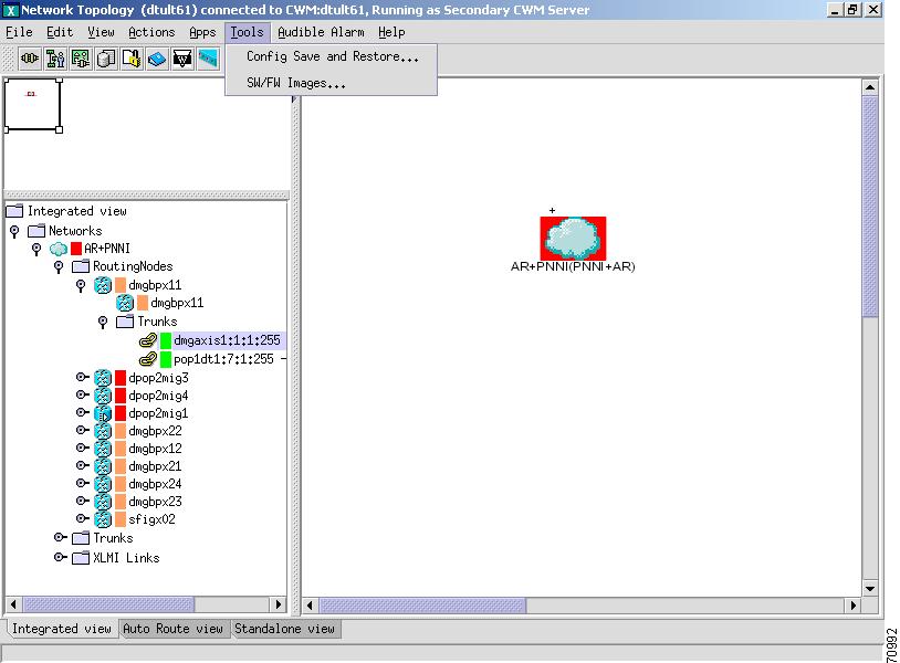
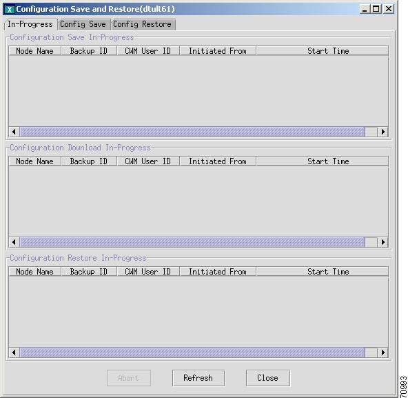
Config Save and Restore
The Config Save and Restore option launches the application shown in Figure 3-45, with In-Progress, Config Save, and Config Restore tabbed windows which allow you to view and change criteria for the selected node in the current submap. See Chapter 13 for additional information about this application.
Figure 3-45 Configuration Save and Restore Window
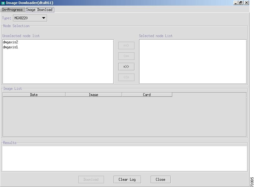
SW/FW Images
The SW/FW (software/firmware) Images option launches the Image Downloader application shown in Figure 3-46. See Chapter 12 for additional information about this application.
Figure 3-46 Image Downloader Window
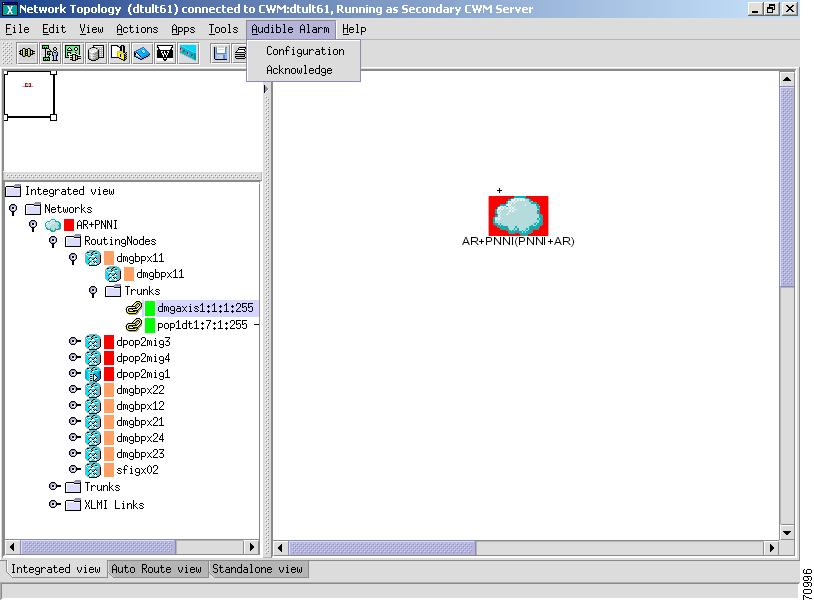
Audible Alarm Menu
The Audible Alarm Menu provides Configuration and Acknowledge alarm menu options, as shown in Figure 3-47.
Figure 3-47 Audible Alarm Menu Options
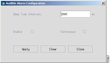
Configuration
Displays an Audible Alarm Configuration window with an editable Beep Time Interval in milliseconds, and Enable and Continuous option settings, as shown in Figure 3-48.
Figure 3-48 Audible Alarm Configuration Window
Acknowledge
Acknowledges the Audible Alarm functionality and configuration.
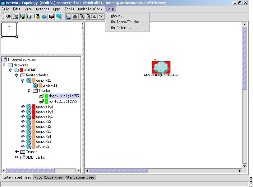
Help Menu
The Help menu, as shown in Figure 3-49, provides submenus with About and Help information that is described below.
Figure 3-49 Help Menu
About
Displays information about this version of the CWM Network Topology GUI.
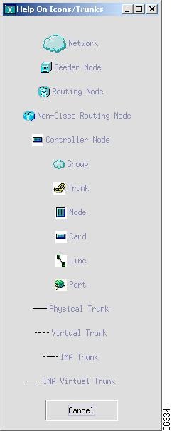
On Icons/Trunks
Displays information about how to interpret the icons and symbols that represent the network elements found in the topology graph window. Figure 3-50 shows the Help On Icons/Trunks window.
Figure 3-50 Help On Icons/Trunks
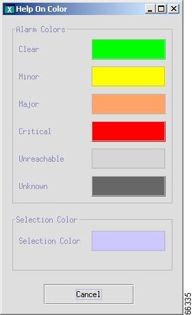
On Color
Information about how to interpret the color of the icons displayed in the topology graph window, as shown in Figure 3-51.
Figure 3-51 Help On Color
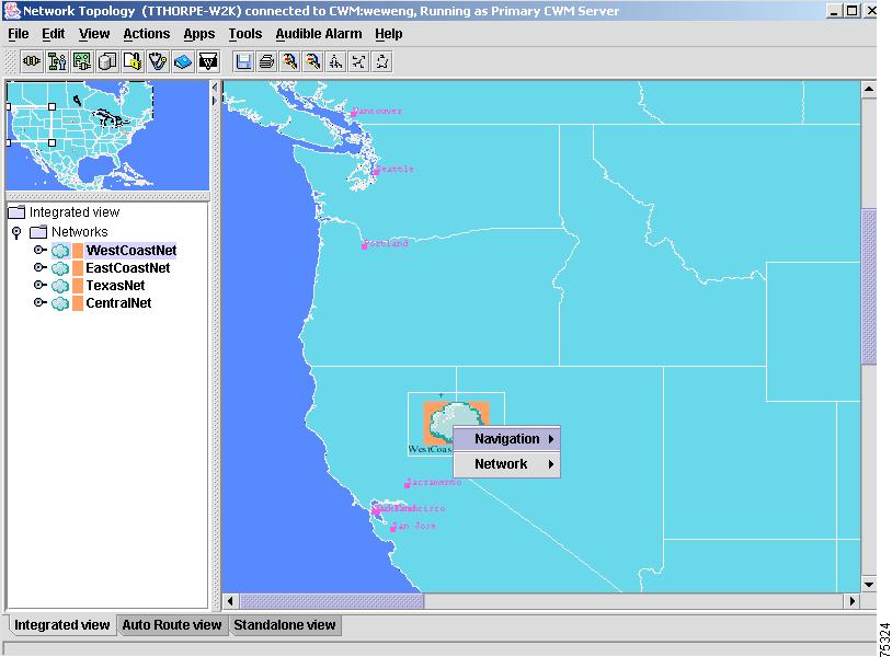
Popup Menus
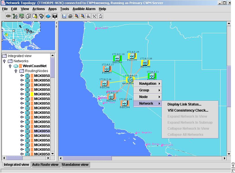
From the right side of the Network Topology's main window, right click on a selected network in order to display Navigation and Network popup menus, as shown in Figure 3-52.
Figure 3-52 Navigation and Network Submenus
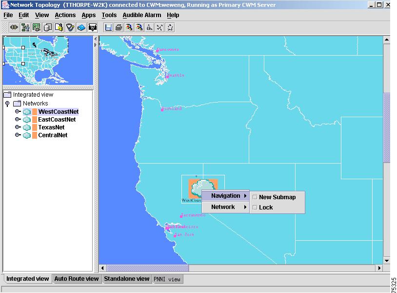
After right clicking on a network to display popup menus, drag your curser to the right in order to view additional menu options for your selected network. The Navigation popup menu includes New Submap, which invokes a new submap window containing an expanded view of the selected network; the Lock option locks the selected network in place. The Navigation popup menus are shown in Figure 3-53.
Note
Figure 3-53 Navigation Submenu Options
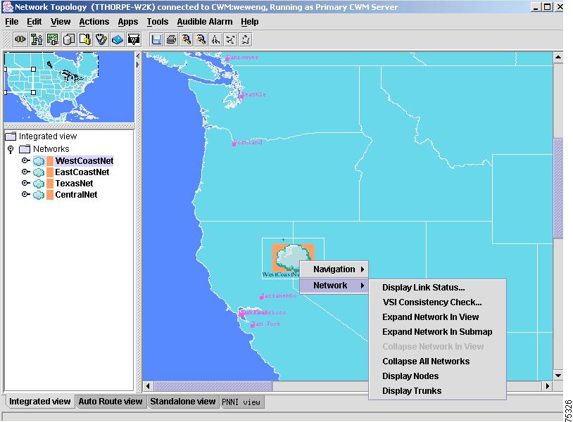
The Network submenu options, shown in Figure 3-54, can also be accessed when selecting a network from the left panel of the Network Topology's main window, and then right clicking on the selected network. The Network submenu options were described earlier in this chapter under "Actions Menu".
Note
Figure 3-54 Network Submenu Options
From the right side of the Network Topology's main window, right click in an area away from the networks, and a window containing Network, Navigation and Background popup menus will appear, as shown in Figure 3-55.
Figure 3-55 Right Click—Network Popup Menus
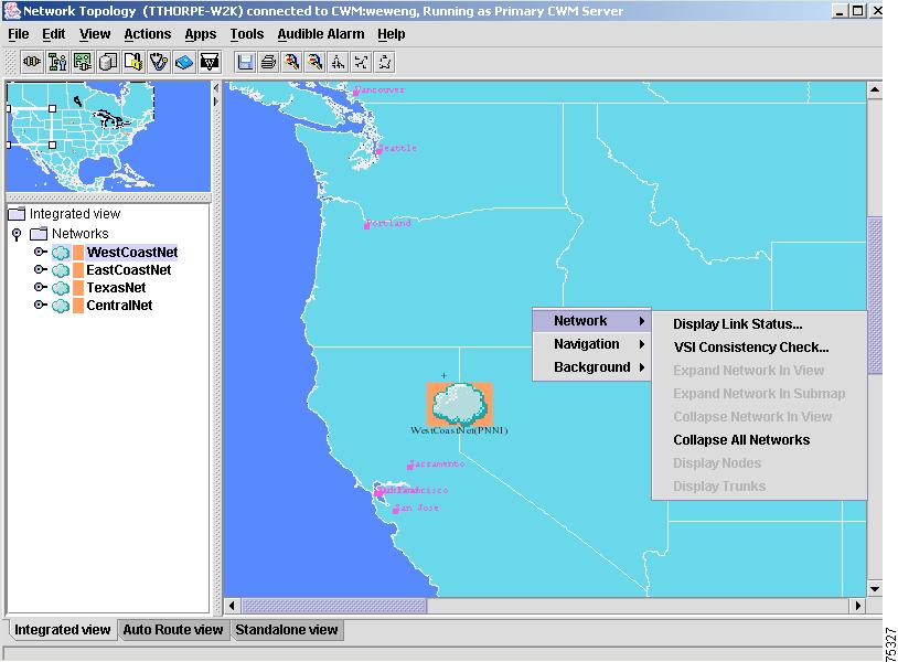
The Network popup menus are the same as those found when right clicking on a network in the right or left panel of the Network Topology's main window.
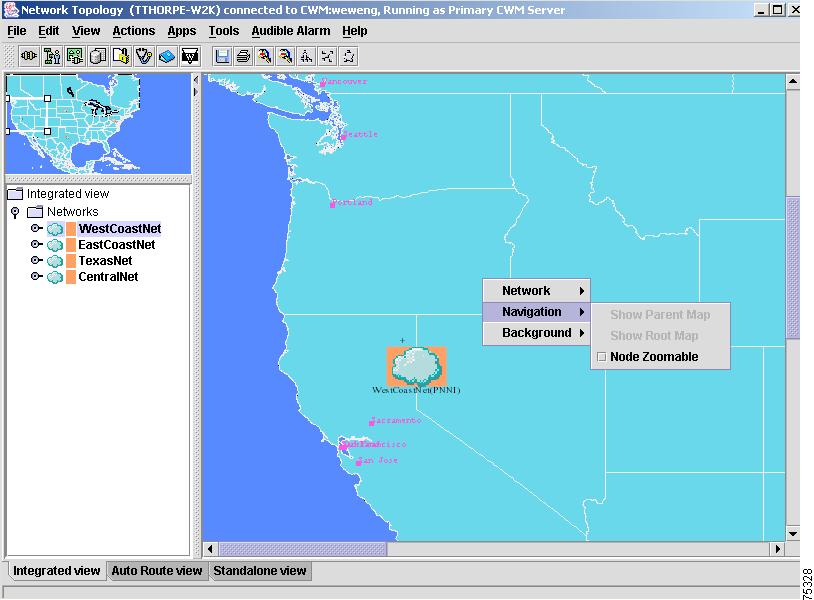
The Navigation popup menus, shown in Figure 3-56, include Show Parent Map, Show Root Map and Node Zoomable. These options are used to display different views of the Network Topology.
Figure 3-56 Navigation Submenu Options
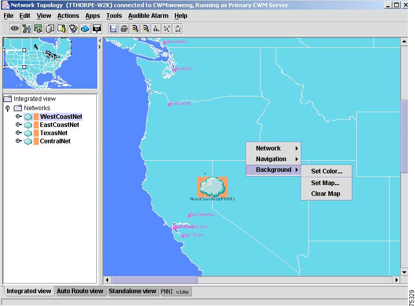
The Background submenu, shown in Figure 3-57, contains the same options that were described earlier in this chapter under "View Menu".
Figure 3-57 Background Submenu Options
Select the Expand Network InView option from the Network popup menu to see an expanded view of the chosen network, including nodes and trunks. Right click on a trunk to view Expand Trunks, Display Trunks and Stop Conn Trace options, as shown in Figure 3-58.
Figure 3-58 Trunk Submenu Options
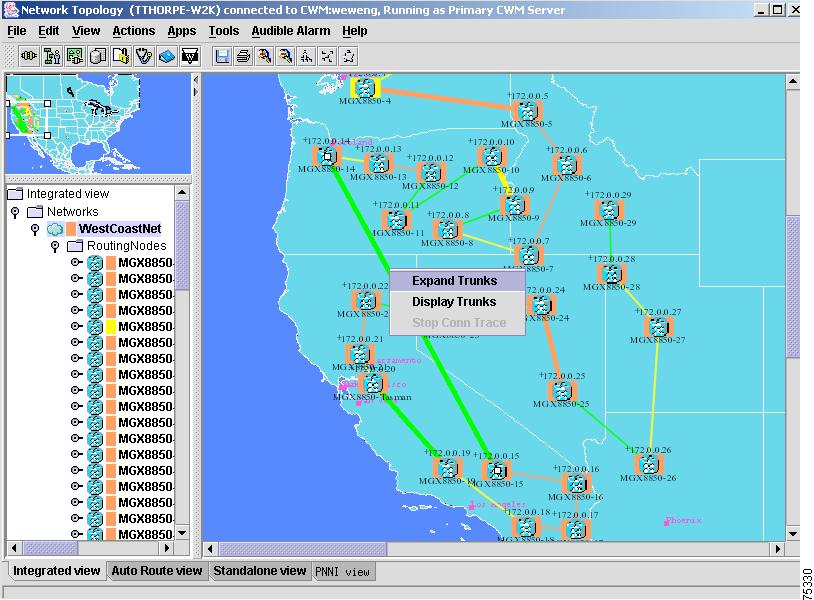
The Expand Trunks and Display Trunks options allow you to view selected trunks; the Stop Conn Trace option stops a connection trace that is already in progress.
If you use the Expand Trunks option to expand the trunk view, the Display Trunks option and Stop Conn Trace option will be the only options available the next time you select a trunk from the Network Topology map, as shown in Figure 3-59.
Note
Figure 3-59 Display Trunks Submenu
Navigation Submenu
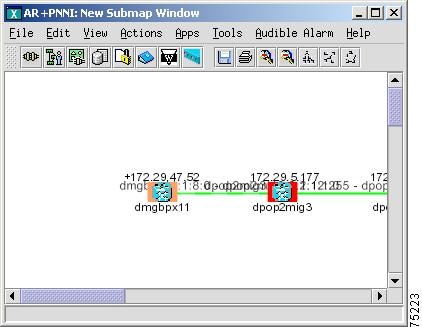
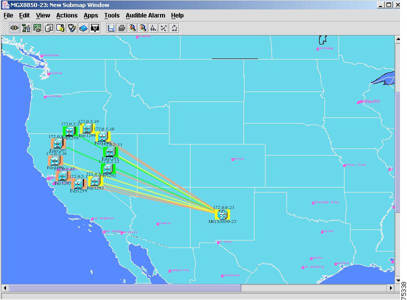
The Navigation submenu provides an additional Network Topology window that appears as a submap on top of the original main window after selecting New Submap from the Navigation dialog window.
Figure 3-60 shows the New Submap window that is launched after selecting New Submap from the Navigation submenu.
Figure 3-60 New Submap Window
Network Submenu
The Network submenu provides the same menu options that are available under the Actions menu's Network submenu: Display Link Status, VSI Consistency Check, Expand Network In View, Expand Network In Submap, Collapse Network In View, Collapse All Networks, Display Nodes and Display Trunks options. See the Actions Menu, for detailed information on all of these options.
Node Submenu
Right click on a node in the left hand panel of the Network Topology main window to display the same menu options that are available under the Actions menu's Node submenu: Display Shelf, Admin, Node Resync, VSI Partition, CiscoView and XPVC Preferred Cnf options. See the Actions Menu, for detailed information on all of these options.
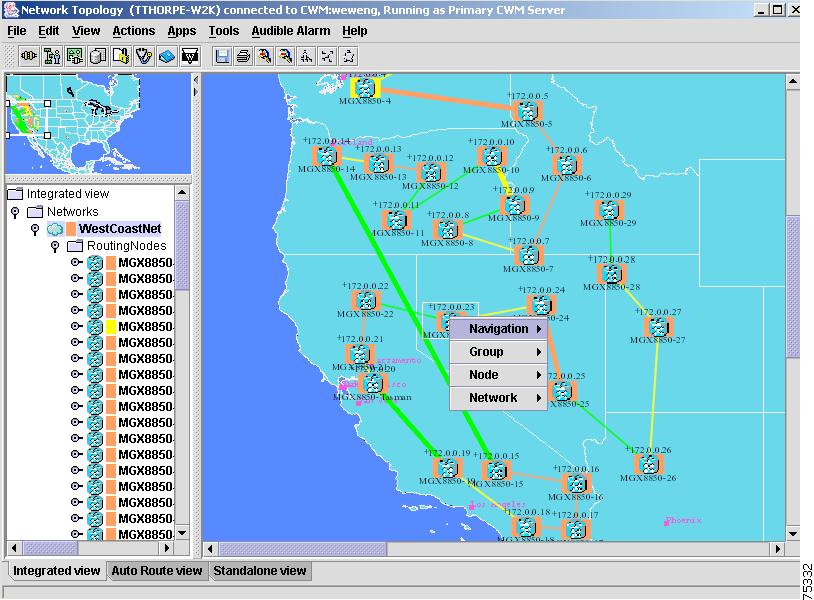
The Navigation, Group, Node and Network menu options are displayed after right clicking in an area outside of the network, as shown in Figure 3-61.
Figure 3-61 Additional Popup Menu Options
Navigation submenu options are shown in Figure 3-62.
Figure 3-62 Navigation Submenu Options
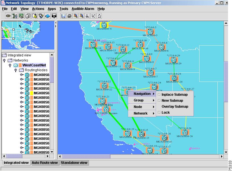
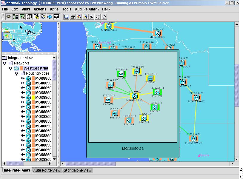
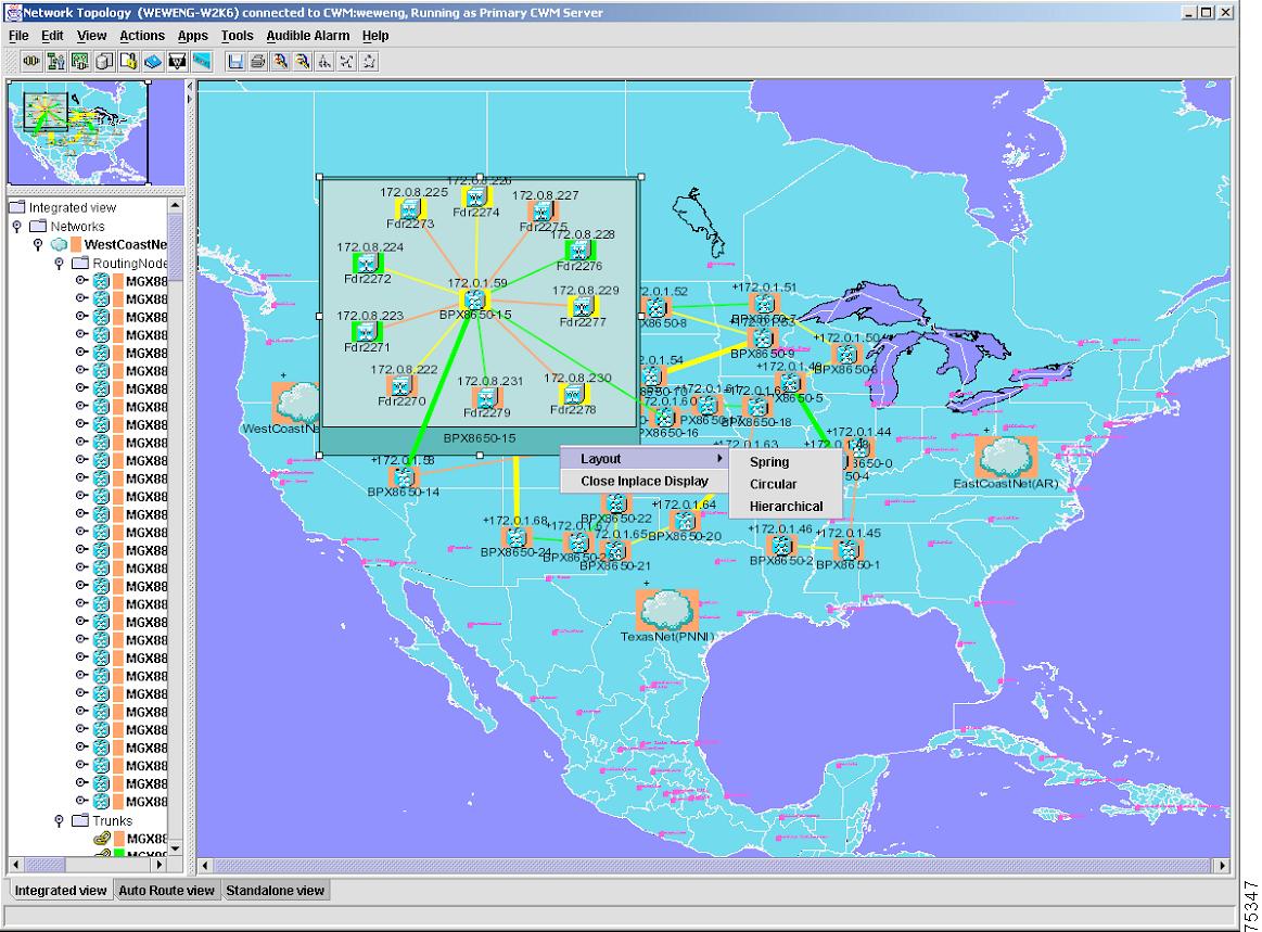
The Inplace submenu option launches a window that shows the selected network in place, as seen in Figure 3-63.
Figure 3-63 Inplace Window
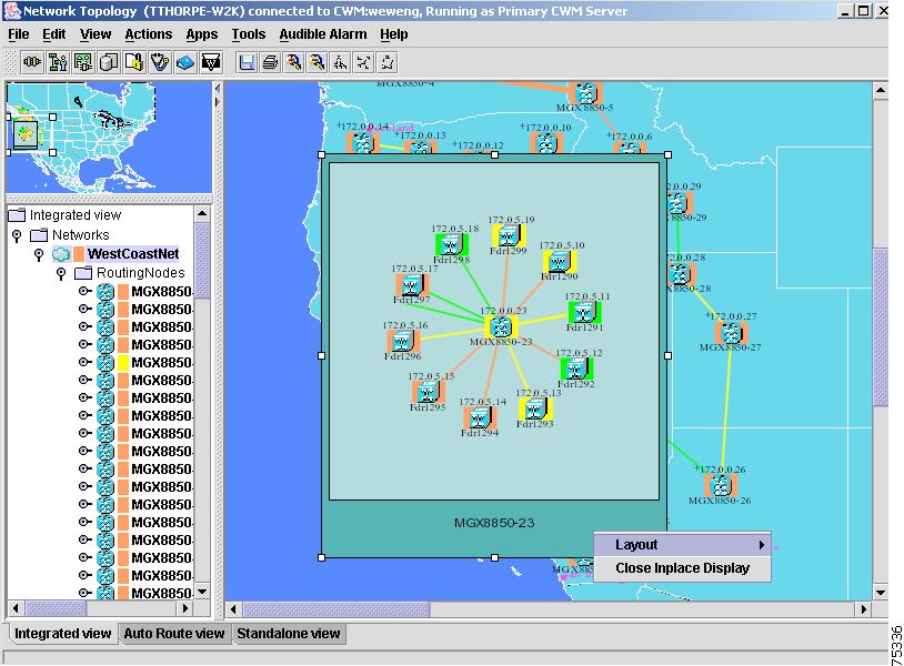
Right click on the border of the Inplace window in order to view additional options, as shown in Figure 3-64.
Figure 3-64 Inplace Submenu Options
The Navigation, New Submap submenu option is shown in Figure 3-65.
Figure 3-65 Navigation Submenu—New Submap
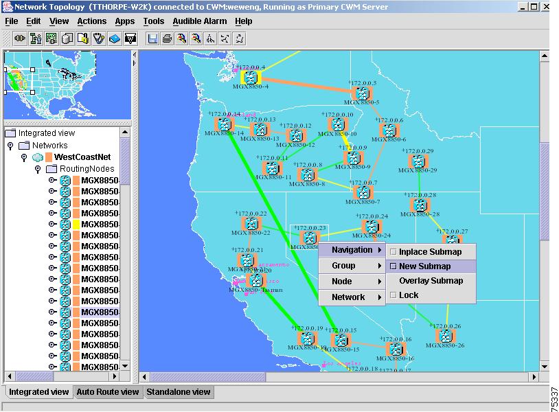
The New Submap window is launched, as shown in Figure 3-66.
Figure 3-66 New Submap
The Navigation, Overlay Submap submenu option is shown in Figure 3-67.
Figure 3-67 Navigation Submenu—Overlay Submap
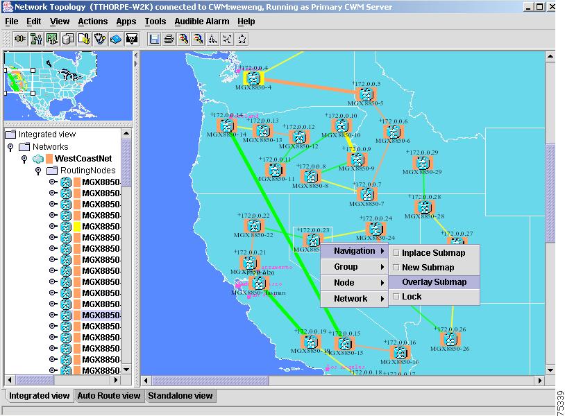
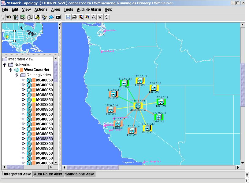
The Overlay Submap window is launched, as shown in Figure 3-68. The Overlay Submap displays a routing node with all of its child nodes. To get out of this image configuration, click on the Network Topology map away from the configuration.
Figure 3-68 Overlay Submap
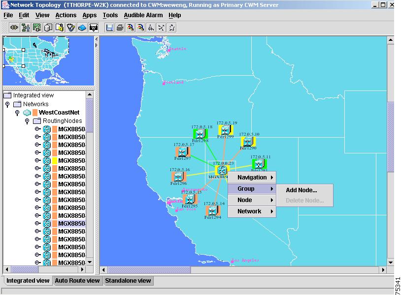
The Group, Add Node submenu option is shown in Figure 3-69.
Figure 3-69 Group Submenu
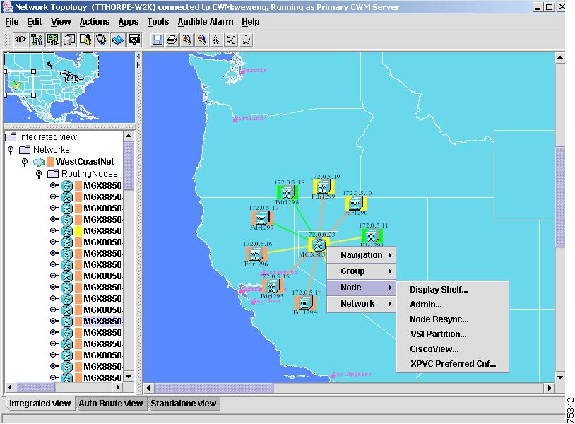
The Node submenu options are shown in Figure 3-70.
Figure 3-70 Node Submenu
The Network submenu options are shown in Figure 3-71.
Figure 3-71 Network Submenu
A magnified trunk view is shown in Figure 3-72.
Figure 3-72 Magnified Trunk View
A Close Inplace display of the network is shown in Figure 3-73.
Figure 3-73 Close Inplace Display of Network
Layout submenu options are shown in Figure 3-74.
Figure 3-74 Layout Submenu Options
Additional Tool Bar Options
Release 11 of CWM provides additional functions that are easily accessed from the CWM Tool bar, as described in the following section.
Save Configuration
The Save Configuration option on the Tool bar provides the same functionality as the Save option found under the File menu.
Print Network Topology
The Print Network Topology option on the Tool bar provides the same functionality as the Print option found under the File menu.
Zoom In
The Zoom In option on the Tool bar shrinks the network into a smaller view, and then displays this new view in both the Network Topology main window and in the upper left panel of the main window.
Zoom Out
The Zoom Out option on the Tool bar expands the network into a larger view, and then displays this new view in both the Network Topology main window and in the upper left panel of the main window.
Layout Tree
The Layout Tree option on the Tool bar displays a new view of the selected node in the upper left panel of the Network Topology main window.
Layout Spring
The Layout Spring option on the Tool bar displays a new view of the selected node in the upper left panel of the Network Topology main window.
Layout Circular
The Layout Circular option on the Tool bar displays a new view of the selected node in the upper left panel of the Network Topology main window.
Network Alarm Colors
CWM uses the following colors to display alarm situations detected by the Network Topology:
•
•
•
•
•
Note
•