Cisco Network Convergence System 6000 Series Routers Hardware Installation Guide
Bias-Free Language
The documentation set for this product strives to use bias-free language. For the purposes of this documentation set, bias-free is defined as language that does not imply discrimination based on age, disability, gender, racial identity, ethnic identity, sexual orientation, socioeconomic status, and intersectionality. Exceptions may be present in the documentation due to language that is hardcoded in the user interfaces of the product software, language used based on RFP documentation, or language that is used by a referenced third-party product. Learn more about how Cisco is using Inclusive Language.
- Updated:
- March 8, 2017
Chapter: Migrating to a Back-to-Back System
Migrating to a Back-to-Back System
The Universal Fabric Card (UFC) supports a back-to-back configuration between two Cisco NCS 6000 LCCs. The back-to-back configuration is supported on Cisco IOS XR release 6.2.1 or later. This appendix describes how to migrate two Cisco NCS 6000 LCC routers from single-chassis to a back-to-back system.
 Note | See the Universal Fabric Card (NC6-FC2-U) section for more information about the UFC. |
- Fabric Overview
- Safety Guidelines
- Prerequisites
- Required Tools and Equipment
- Migrating RACK0 Fabric Planes to Back-to-Back Mode
- Adding RACK1 to Back-to-Back Mode
- Cabling Overview
- Cabling the Ethernet Control Plane
- Cabling the Fabric
- Commands for Router Health Check
Fabric Overview
The Cisco NCS 6000 switch fabric is a three-stage cell based architecture with six fabric planes. The Universal Fabric Card (UFC) in the Cisco NCS 6008 Line Card Chassis LCC implements all 3 stage. The following figure shows a simplified view of the relationship between the line cards and the fabric. The Cisco NCS 6000 back-to-back system has six fabric planes that support data traffic between the lines connected to the LCCs. The fabric planes are numbered 0 through 5.
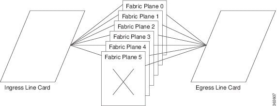
The Line Card Chassis (LCC) has eight line cards (LCs), six UFCs, and 16 CXP modules that connect to the UFCs on the second LCC. The planes do not interconnect with each other but operate independently. Because there are a total of six UFCs in the LCC, the fabric is referred to as having six planes. For example: Slot 0 in LCC0 and LCC1 are all part of plane 0.
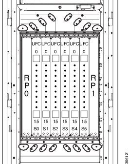
The following figure shows the location of the UFCs in the LCC and how the CXP connectors are labeled. The fabric planes are numbered S0 through S5 and are installed in slot numbers 0 through 5. Each fabric cable connects to one of the UFC connectors (0 through 15), and to a single UFC connector in the second LCC.
Safety Guidelines
Before you perform any procedures, review the safety guidelines in this section to avoid injuring yourself or damaging the equipment. The following guidelines are for your safety and to protect equipment. The guidelines do not include all hazards. Be alert.
-
Review the safety warnings listed in the Regulatory and Compliance Guide for the Cisco NCS 6000 Series Routers before installing, configuring, or troubleshooting any installed card.
-
Never attempt to lift an object that might be too heavy for you to lift by yourself.
-
Keep the work area clear and dust free during and after installation. Do not allow dirt or debris to enter into any laser-based components.
-
Keep tools and router components away from walk areas.
-
Do not wear loose clothing, jewelry, or other items that could get caught in the router while working with cards, modules, and their associated components.
-
Cisco equipment operates safely when used in accordance with its specifications and product-usage instructions.
-
Do not work alone if potentially hazardous conditions exist.
-
The installation must follow national and local electrical codes: in the United States, National Fire Protection Association (NFPA) 70, United States National Electrical Code; in Canada, Canadian Electrical Code, part I, CSA C22.1; in other countries, International Electrotechnical Commission (IEC) 60364, part 1 through part 7.
Prerequisites
-
Before cabling the system, install each line card chassis (LCC) in the planned location. Ensure that you have adequate floor space to cable the back-to-back configuration and an environment that meets the recommended specifications. For more information, see the Cisco Network Convergence System 6000 Series Routers Site Planning Guide.
-
Verify that both single chassis routers (RACK0 and RACK1) are running Cisco IOS XR release 6.2.1 or later (with all applicable SMUs and packages).
-
From each chassis, use the show chassis command from SysAdmin VM and make note of each chassis serial number.
Note
The chassis serial number can also be found on the label on the chassis front/rear face plate. -
Perform the Router Health check on both routers to ensure that any errors or exception are resolved prior to migrating to back-to-back mode. See Commands for Router Health Check.
-
Verify that field-programmable device (FPD) upgrades are completed for all FPDs on both routers by using the show hw-module fpd command. For any FPD components that show status as NEED UPGD, use the upgrade hw-module location location fpd command. For any FPD components that show status as RLOAD REQ, use the hw-module location location reload command.
-
Create a backup of the RACK0 running configuration using the copy running-config command in both System Admin EXEC mode and XR EXEC mode.
Required Tools and Equipment
For a fully-loaded back-to-back configuration, the following Cisco NCS6000 hardware is required:
-
2 Cisco NCS 6000 routers (NCS-6008)
-
4 Fan Trays (NC6-FANTRAY or NC6-FANTRAY-2)

Caution
Both fan trays installed in a chassis must be the same type. Do not install NC6-FANTRAY and NC6-FANTRAY-2 fan trays in the chassis. -
4 Power Trays, with 6 PEM for each Power Tray (NCS-AC-PWRTRAY)
-
4 Route Processors (NC6-RP)
For the Route Processor Ethernet Control connections between RACK0 and RACK1:
-
8 SFP+ optics (SFP-10G-SR)
-
4 LC-to-LC OM3 Multimode cables
-
-
12 Universal Fabric Cards (NC6-FC2-U)
For the Fabric Card connections between RACK0 and RACK1:
-
2 optical module set that includes 96 CXP-100G-SR12 modules each (NCS-FAB-OPT)
-
96 MTP-24 100G Multimode cables
Note
Install a CXP transceiver module or an EMI/dust plug (supplied) in all CXP ports. Do not operate the FC with an open port.
-
-
Supported line cards:
-
NC6-10X100G-M-P—10-port 100Gbps CXP
-
NC6-10X100G-L-P—10-port 100Gbps CXP
-
NC6-10X100G-M-K—10-port 100Gbps CPAK
-
NC6-2/10X100G-L-K—10-port 100Gbps CPAK
-
NC6-60X10GE-L-S—60-port 10Gbps SFP+
-
NC6-60X10GE-M-S—60-port 10Gbps SFP+
Note
The 20-port 100Gbps Line Card (NC6-20X100GE-L-C, NC6-20X100GE-M-C) is not supported in back-to-back configuration. -
Additional required tool and equipment:
-
ESD (Electrostatic Discharge) wrist strap (for inserting a CXP module)
-
Number-2 Phillips screwdriver
-
Cable Director (P/N 2123610-1), to provide support and strain relief for fabric cable connections (provided by Cisco approved vendor Tyco Electronics)
-
Supply of Velcro tie wraps (to bundle cables)
-
Ladder
Migrating RACK0 Fabric Planes to Back-to-Back Mode
Note | This procedure must be completed for each fabric plane, one at a time, on RACK0. |
To migrate to back-to-back mode using the Universal Fabric Cards (UFC), perform the following steps on RACK0:
Review and perform all tasks in the safety guidelines, prerequisites, and required equipment sections before performing this task.
| Step 1 | From SysAdmin VM configuration mode, shut down the fabric plane. Example: sysadmin-vm:0_RP0# config sysadmin-vm:0_RP0(config)# controller fabric plane 0 shutdown sysadmin-vm:0_RP0(config)# commit sysadmin-vm:0_RP0(config)# exit | ||
| Step 2 | Use the show controller fabric plane all detail command to verify that the fabric plane Admin State and Plane State are down. Example: sysadmin-vm:0_RP0# show controller fabric plane all detail Plane Admin Plane Plane up->dn up->mcast Total Down PPU Id State State Mode counter counter Bundles Bundles State ----------------------------------------------------------------- 0 DN DN SC 0 0 16 0 NA 1 UP UP SC 0 0 16 0 NA 2 UP UP SC 0 0 16 0 NA 3 UP UP SC 0 0 16 0 NA 4 UP UP SC 0 0 16 0 NA 5 UP UP SC 0 0 16 0 NA | ||
| Step 3 | From SysAdmin VM configuration mode, power off the fabric card. Example: sysadmin-vm:0_RP0# config sysadmin-vm:0_RP0(config)# hw-module shutdown location 0/FC0 sysadmin-vm:0_RP0(config)# commit sysadmin-vm:0_RP0(config)# exit | ||
| Step 4 | Use the show platform location command to verify that the fabric card is powered off. Example: sysadmin-vm:0_RP0# # show platform location 0/FC0 Mon Dec 5 23:54:02.366 UTC Location Card Type HW State SW State Config State ---------------------------------------------------------------------------- 0/FC0 NC6-FC POWERED_OFF N/A NSHUT | ||
| Step 5 | Remove the legacy fabric card following the steps in the Removing a Fabric Card section. | ||
| Step 6 | Install the UFC following the steps in the Installing a Fabric Card section.
| ||
| Step 7 | From SysAdmin VM configuration mode, change the fabric plane mode to B2B. Example: sysadmin-vm:0_RP0# config sysadmin-vm:0_RP0(config)# controller fabric plane 0 b2b sysadmin-vm:0_RP0(config)# commit sysadmin-vm:0_RP0(config)# exit | ||
| Step 8 | Use the show controller fabric plane all detail command to verify that the fabric plane mode is B2B and that Admin State and Oper State are down. Example: sysadmin-vm:0_RP0# show controller fabric plane all detail Plane Admin Plane Plane up->dn up->mcast Total Down PPU Id State State Mode counter counter Bundles Bundles State ----------------------------------------------------------------- 0 DN DN B2B 0 0 16 0 NA 1 UP UP SC 0 0 16 0 NA 2 UP UP SC 0 0 16 0 NA 3 UP UP SC 0 0 16 0 NA 4 UP UP SC 0 0 16 0 NA 5 UP UP SC 0 0 16 0 NA | ||
| Step 9 | From SysAdmin VM configuration mode, unshut the fabric card. Example: sysadmin-vm:0_RP0# config sysadmin-vm:0_RP0(config)# no hw-module shutdown location 0/FC0 0/RP0/ADMIN0:Dec 5 11:27:52.757 : shelf_mgr[2921]: %INFRA-SHELF_MGR-6-CARD_HW_OPERATIONAL : Card: 0/FC0 hardware state going to Operational 0/RP0/ADMIN0:Dec 5 11:28:09.532 : confd_helper[2900]: %MGBL-CONFD_HELPER-5-SYSADMIN_COMMIT : A sysadmin configuration change has been committed. Use 'show configuration commit list' in admin mode for more details LC/0/0/CPU0:Dec 5 11:28:15.538 : fia_driver[246]: %PLATFORM-CIH-5-ASIC_ERROR_THRESHOLD : fia[2]: A link-err error has occurred. CMIC.CMIC_CMC0_IRQ_STAT3.RTP.Interrupt_Register.LinkMaskChange Threshold has been exceeded LC/0/5/CPU0:Dec 5 11:28:15.740 : fia_driver[216]: %PLATFORM-CIH-5-ASIC_ERROR_THRESHOLD : fia[4]: A link-err error has occurred. CMIC.CMIC_CMC0_IRQ_STAT3.RTP.Interrupt_Register.LinkMaskChange Threshold has been exceeded LC/0/2/CPU0:Dec 5 11:28:15.927 : fia_driver[293]: %PLATFORM-CIH-5-ASIC_ERROR_THRESHOLD : fia[3]: A link-err error has occurred. CMIC.CMIC_CMC0_IRQ_STAT3.RTP.Interrupt_Register.LinkMaskChange Threshold has been exceeded 0/RP0/ADMIN0:Dec 5 11:28:17.401 : fsdbagg[4620]: %FABRIC-FSDB_AGG-5-PLANE_UPDOWN : [4620] : Plane 0 state changed to UP sysadmin-vm:0_RP0(config)# commit sysadmin-vm:0_RP0(config)# exit | ||
| Step 10 | Use the show platform location command to verify that the fabric card is operational. Example: sysadmin-vm:0_RP0# show platform location 0/FC0 Mon Dec 5 23:54:02.366 UTC Location Card Type HW State SW State Config State ---------------------------------------------------------------------------- 0/FC0 NC6-FC2-U OPERATIONAL OPERATIONAL NSHUT | ||
| Step 11 | Use the show hw-module fpd command to verify the status of all FPDs. Verify that no FPD components require an upgrade (as indicated by NEED UPGD in the Status field) and that the Running and Programmed fields display the same version. See the Prerequisites section for FPD upgrade information. | ||
| Step 12 | From SysAdmin VM configuration mode, unshut the fabric plane. Example: sysadmin-vm:0_RP0# config sysadmin-vm:0_RP0(config)# no controller fabric plane 0 shutdown sysadmin-vm:0_RP0(config)# commit sysadmin-vm:0_RP0(config)# exit | ||
| Step 13 | Use the show controller fabric plane all detail command to verify that the Plane Mode is B2B and that Admin State and Plane State are up. Example: sysadmin-vm:0_RP0# show controller fabric plane all detail Plane Admin Plane Plane up->dn up->mcast Total Down PPU Id State State Mode counter counter Bundles Bundles State ----------------------------------------------------------------- 0 UP UP B2B 0 0 16 0 NA 1 UP UP SC 0 0 16 0 NA 2 UP UP SC 0 0 16 0 NA 3 UP UP SC 0 0 16 0 NA 4 UP UP SC 0 0 16 0 NA 5 UP UP SC 0 0 16 0 NA | ||
| Step 14 | Perform the Router Health Check. See Commands for Router Health Check. |
What to Do Next
Repeat these steps for each remaining fabric plane (FC1, FC2, FC3, FC4, and FC5) until all six fabric planes have been migrated to back-to-back mode.
Go to the next section to add RACK1 to back-to-back mode.
Adding RACK1 to Back-to-Back Mode
To add RACK1 to back-to-back mode, perform the following steps:
Review and perform all tasks in the safety guidelines, prerequisites, and required equipment sections before performing this task.
Use the show chassis command and make note of serial number for the chassis.
Perform all steps in the Migrating RACK0 Fabric Planes to Back-to-Back Mode for each fabric plane on RACK0.
| Step 1 | Power off RACK1. |
| Step 2 | Remove all line cards following the steps in the Removing a Line Card section. |
| Step 3 | Remove all legacy fabric cards following the steps in the Removing a Fabric Card section. |
| Step 4 | Install the Universal Fabric Cards (UFCs) following the steps in the Installing a Fabric Card section. |
| Step 5 | Power on RACK1. |
| Step 6 | Use the show hw-module fpd command to verify the status of all FPDs. Verify that no FPD components require an upgrade (as indicated by NEED UPGD in the Status field) and that the Running and Programmed fields display the same version. See the Prerequisites section for FPD upgrade information. |
| Step 7 | Power off RACK1. |
| Step 8 | From SysAdmin VM configuration mode on RACK0, configure the chassis serial numbers. Example: sysadmin-vm:0_RP0# config sysadmin-vm:0_RP0(config)# chassis serial NNN######NA sysadmin-vm:0_RP0(config)# rack 0 sysadmin-vm:0_RP0(config)# chassis serial NNN######NB sysadmin-vm:0_RP0(config)# rack 1 sysadmin-vm:0_RP0(config)# commit |
| Step 9 | Connect the Ethernet Control between RACK0 and RACK1.
See the Cabling the Ethernet Control Plane section. |
| Step 10 | Connect the Fabric between RACK0 and RACK1.
See the Cabling the Fabric section. |
| Step 11 | When all Ethernet Control and Fabric connections have been made, power on RACK1. |
| Step 12 | Use the show platform command to verify that the fabric card is operational. Example: sysadmin-vm:0_RP0# show platform Mon Dec 6 00:54:02.366 UTC Location Card Type HW State SW State Config State --------------------------------------------------------------------------- 0/FC0 NC6-FC OPERATIONAL OPERATIONAL NSHUT 0/FC1 NC6-FC OPERATIONAL OPERATIONAL NSHUT 0/FC2 NC6-FC OPERATIONAL OPERATIONAL NSHUT 0/FC3 NC6-FC OPERATIONAL OPERATIONAL NSHUT 0/FC4 NC6-FC OPERATIONAL OPERATIONAL NSHUT 0/FC5 NC6-FC OPERATIONAL OPERATIONAL NSHUT 0/3 NC6-10X100G-M OPERATIONAL OPERATIONAL NSHUT . . . |
| Step 13 | Perform the Router Health Check. See Commands for Router Health Check. |
| Step 14 | Install the line cards following the steps in the Installing a Line Card section. |
Both RACK0 and RACK1 are in back-to-back mode.
Cabling Overview
Cable Routing Considerations
Cabling Routing
Whether the cables will be run overhead or under the floor, consider the airflow and cable characteristics of the combined cable sets to ensure that your cable management structures support the total capacity of cables for the Cisco NCS 6000 back-to-back system installation.
Raised Floor Installations
To plan cable routing in an installation with a raised floor, consider all the characteristics of each cable required for the installation. Allow slack for cabling so that cables can be pooled under the floor for future expansion without exceeding bend radius or cable length limitations. Riser cables are not rated for installation in air plenum passages, nor are they designed for use in LSZH (low smoke zero halogen) applications.
Cable Characteristics
Plan your cable runs, consider the characteristics of each cable, such as the cable length limitations, combined diameter of bundled cables (such as power cables), weight of the cable groups, and bend radius of the cable or cables. Couple these considerations with the cable infrastructure available (or needed) at your facility. The infrastructure could include structures like the overhead cabling monorail or J-hook system, sleeve and riser diameters, and distances between floors or elements of the Cisco NCS 6000 back-to-back system.
Analyze the cabling infrastructures, risers, and racking available in your facility to determine if the capacity of the cabling management systems at your facility will accommodate the required capacities of the back-to-back system cabling.
Cable Length
The limit of the cables is 100 meters (328 feet). Consider this distance when planning the physical locations of the LCCs. For more information on the range of lengths available for the OM4 fabric cables, contact a Cisco approved vendor such as Tyco Electronics or Molex.
Cable Bend Radius
Exceeding the bend radius allowed for a cable can break the glass in the cable or cause attenuation or loss of signal. Do not bend a cable more than the allowable bend radius.
See the Cisco Network Convergence System 6000 Series Routers Site Planning Guide for information on planning component locations and cable runs.
General Cabling Procedures
Observe these procedures as you attach every cable:
-
Strap the bundles to the horizontal cable management brackets on the chassis.
Four horizontal cable management brackets are preinstalled on the LCC (two on the front side and two on the rear side of each chassis).
-
Handle all fiber-optic cables carefully.
-
Do not allow a fiber-optic cable to bend in a radius smaller than the allowable bend radius specified for that cable type.
-
Fiber-optic cables are glass. Do not step on fiber-optic cables or handle them roughly. Do not twist or stretch the cables.
-
To keep optical connections clean, do not remove the cable dust cover until immediately before you install the cable.
-
After you install a cable, immediately reserve each dust cover for storage by office personnel in a dust-free storage area. After all of the cables have been installed ensure that all the reserved dust covers are stored by office personnel in a dust free area for future use.
-
Install clean dust covers on every unused connection.
-
Consider labeling the chassis interconnection cables or creating a diagram of the cabling to ensure that the cables are connected correctly during system installation.
-
Consider labeling the chassis. Consider whether each chassis need to be physically positioned in sequence. Label each cable with the location of each termination as you install each cable
-
MPO-24 Cable Specifications
Note | Cisco provides the optical modules but does not provide the cables. You can order these cables from a Cisco approved vendor such as Tyco Electronics or Molex. To obtain the optics, please contact your Cisco sales representative for further information. |
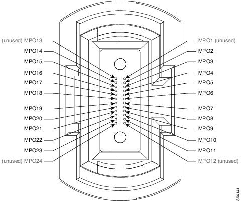
Note | The CXP pluggable transceiver module has 12 dedicated transmit (Tx) channels and 12 receive (Rx) channels per transceiver with data rates up to 10.3125 Gbps and OTN rates up to 11.25 Gbps. The CXP module provides 2-wire serial (I2C) management interface and digital diagnostics, including Tx and Rx optical power monitoring per wavelength. The CXP module uses a 24-fiber MPO connector that supports bidirectional transmission across the fibers (12 Tx + 12 Rx). |
Note | Install a CXP transceiver module or an EMI/dust plug (supplied) in all CXP ports. Do not operate the fabric card with an open port. |
The following figure shows the MPO-24 connector pinouts.
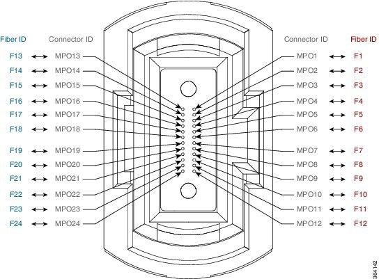
The following figure shows the MPO-24 connector fiber assignments.
The following table lists the 100G to 100G crossover cable connections.
|
MPO Connector |
CXP Module |
Connector |
CXP Module |
||||
|---|---|---|---|---|---|---|---|
|
Connector ID |
Fiber ID |
Pin |
Transmit (TX) Receive (RX) |
Connector ID |
Fiber ID |
Pin |
Transmit (TX) Receive (RX) |
|
MPO1 |
F1 |
1 |
RX |
MPO1 |
F13 |
1 |
RX |
|
MPO2 |
F2 |
2 |
RX |
MPO2 |
F14 |
2 |
RX |
|
MPO3 |
F3 |
3 |
RX |
MPO3 |
F15 |
3 |
RX |
|
MPO4 |
F4 |
4 |
RX |
MPO4 |
F16 |
4 |
RX |
|
MPO5 |
F5 |
5 |
RX |
MPO5 |
F17 |
5 |
RX |
|
MPO6 |
F6 |
6 |
RX |
MPO6 |
F18 |
6 |
RX |
|
MPO7 |
F7 |
7 |
RX |
MPO7 |
F19 |
7 |
RX |
|
MPO8 |
F8 |
8 |
RX |
MPO8 |
F20 |
8 |
RX |
|
MPO9 |
F9 |
9 |
RX |
MPO9 |
F21 |
9 |
RX |
|
MPO10 |
F10 |
10 |
RX |
MPO10 |
F22 |
10 |
RX |
|
MPO11 |
F11 |
11 |
RX |
MPO11 |
F23 |
11 |
RX |
|
MPO12 |
F12 |
12 |
RX |
MPO12 |
F24 |
12 |
RX |
|
MPO13 |
F13 |
13 |
TX |
MPO13 |
F1 |
13 |
TX |
|
MPO14 |
F14 |
14 |
TX |
MPO14 |
F2 |
14 |
TX |
|
MPO15 |
F15 |
15 |
TX |
MPO15 |
F3 |
15 |
TX |
|
MPO16 |
F16 |
16 |
TX |
MPO16 |
F4 |
16 |
TX |
|
MPO17 |
F17 |
17 |
TX |
MPO17 |
F5 |
17 |
TX |
|
MPO18 |
F18 |
18 |
TX |
MPO18 |
F6 |
18 |
TX |
|
MPO19 |
F19 |
19 |
TX |
MPO19 |
F7 |
19 |
TX |
|
MPO20 |
F20 |
20 |
TX |
MPO20 |
F8 |
20 |
TX |
|
MPO21 |
F21 |
21 |
TX |
MPO21 |
F9 |
21 |
TX |
|
MPO22 |
F22 |
22 |
TX |
MPO22 |
F10 |
22 |
TX |
|
MPO23 |
F23 |
23 |
TX |
MPO23 |
F11 |
23 |
TX |
|
MPO24 |
F24 |
24 |
TX |
MPO24 |
F12 |
24 |
TX |
Cabling the Ethernet Control Plane
This section describes how to cable the Ethernet control plane between the RACK0 and RACK1 in mesh configuration to ensure Ethernet control plane failover connectivity across both racks. The Ethernet control plane carries all the signaling, routing updates, system configuration, and management packets for the NCS 6000.
Note | See the Required Tools and Equipment section for more information on the required equipment. |
The following figure shows the Ethernet control plane connections.
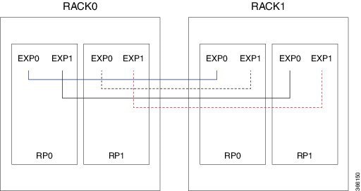
|
RACK0 |
RACK1 |
|---|---|
|
RP0, EXP0 |
RP0, EXP0 |
|
RP0, EXP1 |
RP1, EXP0 |
|
RP1, EXP0 |
RP0, EXP1 |
|
RP1, EXP1 |
RP1, EXP1 |
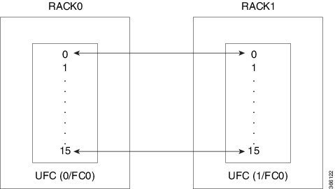
Cabling the Fabric
This section describes how to cable the UFCs between RACK0 and RACK1 for back-to-back mode.
Note | See the Required Tools and Equipment section for more information on the required equipment. |
The fabric provides the data connection for router traffic between all the CXP optical ports in the line card chassis. The fabric cabling must be completed to enable data communications.
The following figure shows the fabric connections for one fabric plane. To complete the configuration, you must repeat the cabling for the remaining five fabric planes until all fabric cards are connected.
|
Plane 0 |
Plane 1 |
< . . . > |
Plane 5 |
|---|---|---|---|
|
RACK0 slot/port to RACK1 slot/port |
|||
|
0/FC0/0 to 1/FC0/0 |
0/FC1/0 to 1/FC1/0 |
< . . . > |
0/FC5/0 to 1/FC5/0 |
|
0/FC0/1 to 1/FC0/1 |
0/FC1/1 to 1/FC1/1 |
< . . . > |
0/FC5/1 to 1/FC5/1 |
|
0/FC0/2 to 1/FC0/2 |
0/FC1/2 to 1/FC1/2 |
< . . . > |
0/FC5/2 to 1/FC5/2 |
|
0/FC0/3 to 1/FC0/3 |
0/FC1/3 to 1/FC1/3 |
< . . . > |
0/FC5/3 to 1/FC5/3 |
|
0/FC0/4 to 1/FC0/4 |
0/FC1/4 to 1/FC1/4 |
< . . . > |
0/FC5/4 to 1/FC5/4 |
|
0/FC0/5 to 1/FC0/5 |
0/FC1/5 to 1/FC1/5 |
< . . . > |
0/FC5/5 to 1/FC5/5 |
|
0/FC0/6 to 1/FC0/6 |
0/FC1/6 to 1/FC1/6 |
< . . . > |
0/FC5/6 to 1/FC5/6 |
|
0/FC0/7 to 1/FC0/7 |
0/FC1/7 to 1/FC1/7 |
< . . . > |
0/FC5/7 to 1/FC5/7 |
|
0/FC0/8 to 1/FC0/8 |
0/FC1/8 to 1/FC1/8 |
< . . . > |
0/FC5/8 to 1/FC5/8 |
|
0/FC0/9 to 1/FC0/9 |
0/FC1/9 to 1/FC1/9 |
< . . . > |
0/FC5/9 to 1/FC5/9 |
|
0/FC0/10 to 1/FC0/10 |
0/FC1/10 to 1/FC1/10 |
< . . . > |
0/FC5/10 to 1/FC5/10 |
|
0/FC0/11 to 1/FC0/11 |
0/FC1/11 to 1/FC1/11 |
< . . . > |
0/FC5/11 to 1/FC5/11 |
|
0/FC0/12 to 1/FC0/12 |
0/FC1/12 to 1/FC1/12 |
< . . . > |
0/FC5/12 to 1/FC5/12 |
|
0/FC0/13 to 1/FC0/13 |
0/FC1/13 to 1/FC1/13 |
< . . . > |
0/FC5/13 to 1/FC5/13 |
|
0/FC0/14 to 1/FC0/14 |
0/FC1/14 to 1/FC1/14 |
< . . . > |
0/FC5/14 to 1/FC5/14 |
|
0/FC0/15 to 1/FC0/15 |
0/FC1/15 to 1/FC1/15 |
< . . . > |
0/FC5/15 to 1/FC5/15 |
Commands for Router Health Check
Use the commands in the following table in System Admin EXEC mode to ensure that any errors or exception are resolved prior to and after migration of back-to-back configuration.
|
Command |
Description |
||
|---|---|---|---|
|
show chassis |
Verify that both Data Plane and Control Plane are connected. |
||
|
show platform |
Verify that all nodes are operational. |
||
|
show vm |
Verify that all VMs are running (both Sysadmin and XR). |
||
|
show install active |
Verify that the packages are active on all nodes. |
||
|
show install committed |
Verify that the packages are committed on all nodes. |
||
|
show controller switch reachable |
Verify that all RPs and LCs inserted in the router are listed. |
||
|
show controller switch mlap reachable |
Verify that all RPs are listed. |
||
|
show controller switch mlap statistics location location
|
Verify that all connected ports are in Active or Standby state; any ports in UP protocol state are unexpected. |
||
|
show controller switch summary location location |
Verify that the Physical and Admin State of all the connected ports are UP. |
||
|
show controller fabric plane all detail |
Verify the Fabric Plane state and Bundle state. |
||
|
show controller switch summary |
Verify the state of Exp Eth 0 and Exp Eth 1 ports. One port must be in Active (Forwarding) state, and one port must be in Standby (Blocking) state.
Verify that the connected ports are in up, active, and forwarding state. If the states are not displayed correctly, check the control Ethernet cabling. |
||
|
show controller fabric plane all statistics |
Check for CE, UCE, and Parity Errors. |
||
|
show controller fabric sfe s13 all |
Check the S13 ASIC state. |
||
|
show controller fabric sfe fia all |
Check the FIA ASIC states. |
||
|
show controller sfe driver rack rack_number |
Check the software state of the UFC. |
||
|
show sdr default-sdr pairing |
Provides info on which is the SDR lead.
|
||
|
show context location all |
Checks for any crashes that might have occurred. |
Use the commands in the following table in XR EXEC mode to ensure that any errors or exception are resolved prior to and after migration of back-to-back configuration.
|
Command |
Description |
||
|---|---|---|---|
|
show platform |
Verify that each node CPU displays IOS XR RUN, and that the config state is NSHUT. Verify that all the slices of line cards (if present) are in UP state. |
||
|
show redundancy summary |
Verify Node and NSR status is Ready. |
||
|
show processes blocked location node_ID |
Check for blocked processes.
|
||
|
show processes cpu location node_ID |
Check the CPU utilization. |
||
|
show controllers fia driver locationnode_ID |
Check the software state of FIA. |
||
|
show controllers pse summary location node_ID |
Check the PPE Utilization, Block Initialization, and Alignment Status.
|
Use the commands in the following table in System Admin EXEC mode to check the state of the fabric.
 Feedback