Troubleshooting Overview
This section describes the methods used in troubleshooting the router. The troubleshooting methods are organized according to the major subsystems in the router.
If you are unable to solve a problem on your own, you can contact a Cisco customer service representative for assistance. When you call, have this information ready:
- Date you received the router and the chassis serial number (located on a label on the back of the chassis).
- Installed line card and Cisco
software release number:
- Use the show version command to determine the Cisco software release number.
- Brief description of the symptoms and steps you have taken to isolate and solve the issue.
- Maintenance agreement or warranty information.
Troubleshooting Using a Subsystem Approach
To solve a system problem, try to isolate the problem to a specific subsystem. Compare the current router behavior with the expected router behavior. Because a startup issue is usually attributable to one component, it is most efficient to examine each subsystem, rather than trying to troubleshoot each router component.
For troubleshooting purposes in this chapter, the router consists of these subsystems:
-
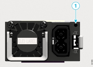
Power subsystem—Router chassis is shipped with up to two AC-input or DC-input power supply modules installed in the chassis.

Note
The Cisco ASR 9902 router is not shipped with power supply modules installed in the chassis. However, the power modules are packed along with the chassis.
-
Chassis backplane power distribution—System transfers +12 VDC power from the power modules to the chassis backplane and distributes it to all the cards through the backplane connectors. The fan tray receives power from the chassis backplane and communicate to the RP CAN Bus controller.
-
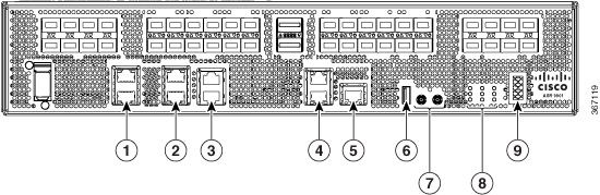
Processor subsystem—Includes the active Route Processor (RP) card with line card. The RP is equipped with onboard processors. The RP downloads a copy of the Cisco software image to the line card processor.
-
Cooling subsystem—The fan trays circulate cooling air through the chassis.
-
Cisco ASR 9001 Router has one fan tray (with 14 fans).
-
Cisco ASR 9901 Router has three fan trays.
-
Cisco ASR 9903 Router has four fan trays.
-
Cisco ASR 9902 Router has three fan trays.
-
Normal Router Startup Sequence
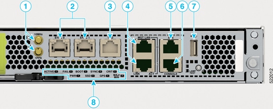
You can generally determine when and where the router failed during the startup sequence by checking the status LEDs on the power modules and RP.
In a normal router startup sequence, this sequence of events and conditions occur:
Procedure
|
Step 1 |
The fan in each power module receives power and begins drawing air through the power supply. |
|
Step 2 |
The fans in the fan tray receive power and begin drawing air through the chassis. The fan tray OK indicator is on. |
|
Step 3 |
As the power-on and boot process progresses for the RP, the status of the RP appears on the front panel of the card. |
Identifying Startup Issues
The following table shows the LED states on the power modules (AC or DC), RP, and the fan tray after a successful system startup.
|
Component |
Type of Indicator |
Display Contents/LED Status and Meaning |
|---|---|---|
|
Line Card |
Status LED |
Green: The line card is enabled and ready for use. |
|
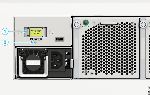
AC Power Modules |
Power status LEDs |
Green (ON): Input AC power OK. Amber (OFF): No fault is present. The correct power module voltages are present and no faults have been detected. |
|
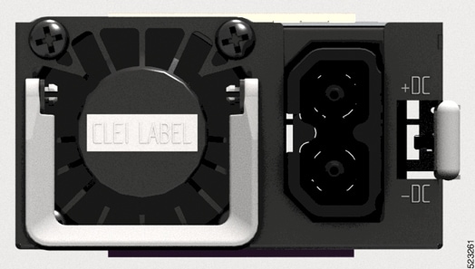
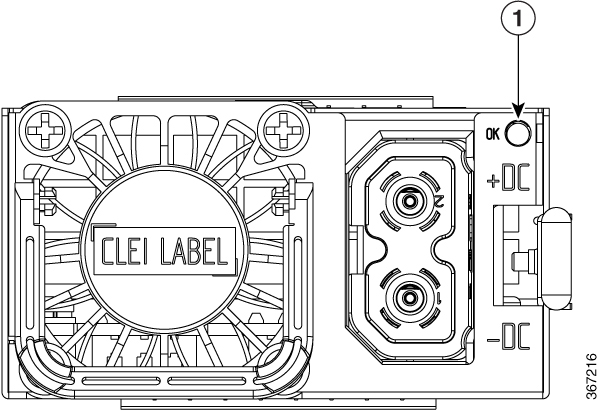
DC Power Modules |
Power status LEDs |
Green (ON): Input DC power OK. Amber (OFF): No fault is present. The correct power module voltages are present and no faults have been detected. |
|
Fan Tray |
Fan tray status LED |
Green (ON): Fan Tray OK. The fan tray fans are operating correctly. |
 Feedback