- Zone-based Policy Firewall
- VRF Aware Cisco IOS Firewall
- Cisco Firewall�SIP Enhancements: ALG
- Configuring Firewall Stateful Inter-Chassis Redundancy
- vTCP for ALG Support
- Firewall Stateful Inspection of ICMP
- Configuring the VRF-Aware Service Infrastructure
- Configuring Firewall Resource Management
- Configuring Firewall TCP SYN Cookie
Security Configuration Guide: Zone-Based Policy Firewall Cisco IOS XE Release 3S
Bias-Free Language
The documentation set for this product strives to use bias-free language. For the purposes of this documentation set, bias-free is defined as language that does not imply discrimination based on age, disability, gender, racial identity, ethnic identity, sexual orientation, socioeconomic status, and intersectionality. Exceptions may be present in the documentation due to language that is hardcoded in the user interfaces of the product software, language used based on RFP documentation, or language that is used by a referenced third-party product. Learn more about how Cisco is using Inclusive Language.
- Updated:
- October 9, 2009
Chapter: VRF Aware Cisco IOS Firewall
- Finding Feature Information
- Contents
- Prerequisites for VRF Aware Cisco IOS XE Firewall
- Restrictions for VRF Aware Cisco IOS XE Firewall
- Information About VRF Aware Cisco IOS XE Firewall
VRF Aware Cisco IOS XE Firewall
The VRF-Aware Cisco IOS XE Firewall applies the Cisco IOS XE Firewall functionality to VPN Routing and Forwarding (VRF) interfaces when the firewall is configured on a service provider (SP) or large enterprise edge routers. SPs provide managed services to small and medium business markets.
The VRF-Aware Cisco IOS XE Firewall supports VRF-lite (also known as Multi-VRF CE) and Application Inspection and Control (AIC) for various protocols.
 |
Note |
Finding Feature Information
Your software release may not support all the features documented in this module. For the latest feature information and caveats, see the release notes for your platform and software release. To find information about the features documented in this module, and to see a list of the releases in which each feature is supported, see the "Feature Information for VRF Aware Cisco IOS XE Firewall" section.
Use Cisco Feature Navigator to find information about platform support and Cisco software image support. To access Cisco Feature Navigator, go to http://www.cisco.com/go/cfn. An account on Cisco.com is not required.
Contents
•![]() Prerequisites for VRF Aware Cisco IOS XE Firewall
Prerequisites for VRF Aware Cisco IOS XE Firewall
•![]() Restrictions for VRF Aware Cisco IOS XE Firewall
Restrictions for VRF Aware Cisco IOS XE Firewall
•![]() Information About VRF Aware Cisco IOS XE Firewall
Information About VRF Aware Cisco IOS XE Firewall
•![]() How to Configure VRF Aware Cisco XE IOS Firewall
How to Configure VRF Aware Cisco XE IOS Firewall
•![]() Configuration Examples for VRF Aware Cisco IOS XE Firewall
Configuration Examples for VRF Aware Cisco IOS XE Firewall
•![]() Feature Information for VRF Aware Cisco IOS XE Firewall
Feature Information for VRF Aware Cisco IOS XE Firewall
Prerequisites for VRF Aware Cisco IOS XE Firewall
•![]() Understand Cisco IOS XE firewalls.
Understand Cisco IOS XE firewalls.
•![]() Configure VRFs.
Configure VRFs.
Restrictions for VRF Aware Cisco IOS XE Firewall
•![]() If two VPN networks have overlapping addresses, VRF-aware Network Address Translation (NAT) is required for them to support VRF-aware firewalls. NAT does not support inter-VRF routing. You can use the VRF-aware software infrastructure (VASI) for the inter-VRF routing functionality.
If two VPN networks have overlapping addresses, VRF-aware Network Address Translation (NAT) is required for them to support VRF-aware firewalls. NAT does not support inter-VRF routing. You can use the VRF-aware software infrastructure (VASI) for the inter-VRF routing functionality.
•![]() When crypto tunnels that belong to multiple VPNs terminate on a single interface, you cannot apply per-VRF firewall policies.
When crypto tunnels that belong to multiple VPNs terminate on a single interface, you cannot apply per-VRF firewall policies.
•![]() The same zone cannot be applied to interfaces that are configured on different VRFs.
The same zone cannot be applied to interfaces that are configured on different VRFs.
Information About VRF Aware Cisco IOS XE Firewall
•![]() VRF-Aware Cisco IOS XE Firewall
VRF-Aware Cisco IOS XE Firewall
•![]() VRF
VRF
•![]() VRF-Aware Software Infrastructure
VRF-Aware Software Infrastructure
•![]() VRF Aware Cisco IOS XE Firewall Deployment
VRF Aware Cisco IOS XE Firewall Deployment
VRF-Aware Cisco IOS XE Firewall
A VRF-aware firewall inspects IP packets that are sent or received within a VRF. VRF allows multiple instances of routing tables to coexist within a single router. This allows VPN segregation and the ability to have independent overlapping of IP address spaces. VRF allows traffic from the customers of one service provider to be isolated from another. The Cisco IOS XE VRF support splits the router into multiple routing domains, with each routing domain consisting of its own set of interfaces and routing and forwarding tables. Each routing domain is referenced by a unique identifier called the table ID. The global routing domain and the default routing domain (that is not associated with any VRF) is addressed with the table ID, zero. VRF supports overlapping of IP address space, thereby allowing the traffic from nonintersecting VRFs to have the same IP address.
The VRF-Aware Cisco IOS XE Firewall provides the following benefits:
•![]() Scalable deployment--Scales to meet any networkâ??s bandwidth and performance requirements.
Scalable deployment--Scales to meet any networkâ??s bandwidth and performance requirements.
•![]() VPN support--Provides a complete VPN solution based on Cisco IOS XE IPsec and other software-based technologies, including Layer 2 Tunneling Protocol (L2TP) tunneling, and quality of service (QoS).
VPN support--Provides a complete VPN solution based on Cisco IOS XE IPsec and other software-based technologies, including Layer 2 Tunneling Protocol (L2TP) tunneling, and quality of service (QoS).
•![]() AIC support--Provides policy maps for the Internet Control Message Protocol (ICMP), Internet Message Access Protocol (IMAP), Post Office Protocol 3 (POP3), Simple Mail Transfer Protocol (SMTP), and Sun Remote Procedure Call (SUN RPC)
AIC support--Provides policy maps for the Internet Control Message Protocol (ICMP), Internet Message Access Protocol (IMAP), Post Office Protocol 3 (POP3), Simple Mail Transfer Protocol (SMTP), and Sun Remote Procedure Call (SUN RPC)
•![]() Allows users to configure a per-VRF firewall. The firewall inspects IP packets that are sent and received within a VRF. The firewall also inspects traffic between two different VRFs (intersecting VRFs).
Allows users to configure a per-VRF firewall. The firewall inspects IP packets that are sent and received within a VRF. The firewall also inspects traffic between two different VRFs (intersecting VRFs).
•![]() Allows SPs to deploy the firewall on the provider edge (PE) router.
Allows SPs to deploy the firewall on the provider edge (PE) router.
•![]() Supports overlapping IP address space, thereby allowing traffic from nonintersecting VRFs to have the same IP address.
Supports overlapping IP address space, thereby allowing traffic from nonintersecting VRFs to have the same IP address.
•![]() Supports VRF (not global) firewall command parameters and Denial-of-Service (DoS) parameters so that the VRF-aware firewall can run as multiple instances (with VRF instances) that are allocated to various VPN customers.
Supports VRF (not global) firewall command parameters and Denial-of-Service (DoS) parameters so that the VRF-aware firewall can run as multiple instances (with VRF instances) that are allocated to various VPN customers.
•![]() Generates high-speed logging (HSL) messages that contain the VRF ID; however these messages are collected by a single collector.
Generates high-speed logging (HSL) messages that contain the VRF ID; however these messages are collected by a single collector.
The VRF-aware firewall allows you to limit the number of firewall sessions. If the firewall sessions are not limited, it would be difficult for VRFs to share router resources because one VRF may consume a maximum amount of resources, leaving few resources for other VRFs and thereby causing the denial of service to other VRFs.
Address Space Overlap
A VRF splits the router into multiple routing domains. Each of these routing domains contain their own set of interfaces and routing tables. A routing table is referenced by using a per-VRF unique table ID. Zero is the default routing table ID that is not associated with any VRF.
Nonintersecting VRFs are allowed to have overlapping address spaces (that is, the IP address of one VRF may be contained in others). Firewall sessions are bidirectional and contain normalized keys that are made up of 7-tuple. A tuple is an ordered list of elements. The 7-tuple normalized key consists of the source IP address, destination IP address, protocol, and the Layer 4 source, destination ports normalized so that the IP addresses are numerically sorted within the key, and the source and destination VRF IDs.
VRF
VRF allows multiple instances of routing tables to coexit within a single router. A VRF contains a template of a VRF table in a PE router.
The overlapping addresses, usually resulting from the use of private IP addresses in customer networks, are one of the major obstacles to the successful deployment of a peer-to-peer VPN implementation. You can use the MPLS VPN technology to overcome the overlapping addresses issue.
Each VPN has its own routing and forwarding table in the router so that any customer or site that belongs to a VPN is provided access only to the set of routes contained within that table. Any PE router in the MPLS VPN network therefore contains a number of per-VPN routing tables and a global routing table that is used to reach other routers in the service provider network. Effectively, a number of virtual routers are created in a single physical router.
VRF-Lite
The VRF-Lite Aware Firewall feature, also called the VRF without MPLS-aware firewall, allows a firewall zone to be applied to non-MPLS-enabled VRF interfaces.
The VRF-Lite Aware Firewall feature enables a service provider to support two or more VPNs, in which IP addresses can be overlapped among the VPNs. VRF-lite uses input interfaces to distinguish routes for different VPNs and forms virtual packet-forwarding tables by associating one or more Layer 3 interfaces with each VRF. Interfaces in a VRF can be physical, such as Ethernet ports, or logical, such as VLAN switched virtual interfaces (SVIs). However, a Layer 3 interface cannot belong to more than one VRF at a time.
|
Note |
VRF-lite includes the following devices:
Customer edge (CE) devices provide customers access to the service provider network over a data link. The CE device advertises the siteâ??s local routes to the PE router and learns about the remote VPN routes from the PE router.
PE routers exchange routing information with CE devices by using static routing or a routing protocol such as Border Gateway Protocol (BGP), Routing Information Protocol Version 1 (RIPv1), or RIPv2.
Provider routers (or core routers) are any routers in the service provider network that are not attached to CE devices.
A PE router is only required to maintain VPN routes for those VPNs to which it is directly attached, eliminating the need for the PE router to maintain all the service provider VPN routes. Each PE router maintains a VRF for each of its directly connected sites. Multiple interfaces on a PE router can be associated with a single VRF, if all of these sites are part of the same VPN. Each VPN is mapped to a specified VRF. After learning local VPN routes from CE routers, a PE router exchanges VPN routing information with other PE routers by using internal BGP (iBPG).
With VRF-lite, multiple customers can share one CE router, and only one physical link is used between the CE router and the PE router. The shared CE router maintains a separate VRF table for each customer, and switches or routes packets for each customer based on its own routing table. VRF-lite extends the limited PE router functionality to a CE device, giving it the ability to maintain separate VRF tables to extend the privacy and security of a VPN to the branch office.
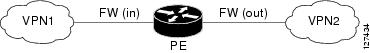
In a VRF-to-VRF situation, if firewall policies are applied on both ingress and egress interfaces as shown in the Figure 1, the firewall on the ingress interface takes precedence over the firewall on the egress interface. If the incoming packets do not match the firewall rules (that is, the inspection protocols) configured on the ingress interface, the firewall rules on the egress interface is applied to the packet.
Figure 1 Firewall in a VRF-to-VRF Scenario
MPLS VPN
The MPLS VPN feature allows multiple sites to interconnect transparently through a service provider network. One service provider network can support several IP VPNs. Each VPN appears to its users as a private network, separate from all other networks. Within a VPN, each site can send IP packets to any other site in the same VPN.
Each VPN is associated with one or more VPN VRF instances. A VRF consists of an IP routing table, a derived Cisco Express Forwarding table, and a set of interfaces that use the forwarding table.
The router maintains a separate routing and Cisco Express Forwarding tables for each VRF. This prevents information from being sent outside the VPN and allows the same subnet to be used in several VPNs without causing duplicate IP address problems.
The router using Multiprotocol BGP (MP-BGP) distributes the VPN routing information using the MP-BGP extended communities.
VRF-Aware NAT
Network Address Translation (NAT) allows a single device, such as a router, to act as an agent between the Internet (or public network) and a local (or private) network. Although NAT systems can provide broad levels of security advantages, their main objective is to economize on address space.
NAT allows organizations to resolve the problem of IP address depletion when they have existing networks and need to access the Internet. Sites that do not possess NIC-registered IP addresses must acquire them. Cisco IOS XE NAT eliminates the concern of NIC-registered IP addresses by dynamically mapping thousands of hidden internal addresses to a range of easy-to-get addresses.
A NAT system makes it difficult for an attacker to determine the following:
•![]() The number of systems running on a network.
The number of systems running on a network.
•![]() Type of machines and operating systems they are running.
Type of machines and operating systems they are running.
•![]() Network topology and arrangement.
Network topology and arrangement.
NAT integration with MPLS VPNs allows multiple MPLS VPNs to be configured on a single device to work together. NAT can differentiate the MPLS VPNs from which it receives the IP traffic, even if all the MPLS VPN use the same IP addressing scheme. This enables multiple MPLS VPN customers to share services while ensuring that each MPLS VPN is completely separate from the other.
To provide value-added services, such as, Internet connectivity, domain name servers (DNS), and VoIP service to customers, the MPLS service providers must use NAT. NAT helps the MPLS VPN customers to use overlapped IP addresses in their network.
NAT can be implemented on a CE router or on a PE router. The NAT integration with the MPLS VPNs feature enables the implementation of NAT on a PE router in an MPLS cloud.
VRF-Aware ALG
An application-layer gateway (ALG) is an application that translates the IP address information inside the payload of an application packet. The ALGs identify the address information in the packet payload that needs to be overwritten by NAT and supply the address information to NAT and firewall to create subordinate flows or pinholes to allow data to flow properly (an example of data flow is FTP data flow). A pinhole is a port that is opened through NAT or firewall to allow a particular application to gain controlled access to a network.
VRF-Aware IPsec
The VRF-Aware IPsec feature maps an IPsec tunnel to an MPLS VPN. Using the VRF-Aware IPsec feature, you can map IPsec tunnels to VRF instances using a single public-facing IP address.
Each IPsec tunnel is associated with two VRF domains. The outer encapsulated packet belongs to a VRF domain called the Front Door VRF (FVRF). The inner, protected IP packet belongs to a domain called the Inside VRF (IVRF). In other words, the local endpoint of the IPsec tunnel belongs to the FVRF, whereas the source and destination addresses of the inside packet belong to the IVRF.
One or more IPsec tunnels can terminate on a single interface. The FVRF of all these tunnels is the same and is set to the VRF that is configured on that interface. The IVRF of these tunnels can be different and depends on the VRF that is defined in the Internet Security Association and Key Management Protocol (ISAKMP) profile that is attached to a crypto map entry.
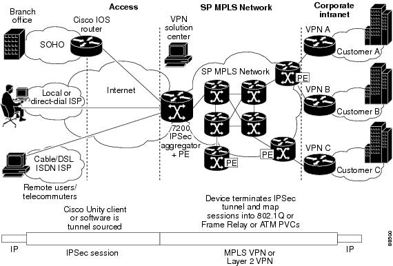
Figure 2 illustrates a scenario showing IPsec to MPLS and Layer 2 VPNs.
Figure 2 IPsec-to-MPLS and Layer 2 VPNs
VRF-Aware Software Infrastructure
The VRF-Aware Software Infrastructure (VASI) allows you to apply services such as access control lists (ACLs), NAT, policing, and zone-based firewalls to traffic that is flowing across two different VRF instances. The VASI interfaces support redundancy of the Route Processor (RP) and Forwarding Processor (FP). This feature supports IPv4 and IPv6 unicast traffic on VASI interfaces.
VASI is implemented by using virtual interface pairs, where each of the interfaces in the pair is associated with a different VRF. The VASI virtual interface is the next hop interface for any packet that needs to be switched between these two VRFs. VASI interfaces provide the framework necessary to support NAT between two VRFs.
Security Zones
A security zone is a group of interfaces to which a policy can be applied.
Grouping interfaces into zones involves two procedures:
•![]() Creating a zone so that interfaces can be attached to it.
Creating a zone so that interfaces can be attached to it.
•![]() Configuring an interface to be a member of a given zone.
Configuring an interface to be a member of a given zone.
By default, traffic flows among interfaces that are members of the same zone.
When an interface is a member of a security zone, all traffic (except traffic going to the router or initiated by the router) between that interface and an interface within a different zone is dropped by default. To permit traffic to and from a zone-member interface and another interface, you must make that zone part of a zone pair and apply a policy to that zone pair. If the policy permits traffic (through inspect or pass actions), traffic can flow through the interface.
Basic rules to consider when setting up zones are as follows:
•![]() Traffic from a zone interface to a nonzone interface or from a nonzone interface to a zone interface is always dropped; unless default zones are enabled (default zone is a nonzone interface).
Traffic from a zone interface to a nonzone interface or from a nonzone interface to a zone interface is always dropped; unless default zones are enabled (default zone is a nonzone interface).
•![]() Traffic between two zone interfaces is inspected if there is a zone-pair relationship for each zone and if there is a configured policy for that zone pair.
Traffic between two zone interfaces is inspected if there is a zone-pair relationship for each zone and if there is a configured policy for that zone pair.
•![]() By default, all traffic between two interfaces in the same zone is always allowed.
By default, all traffic between two interfaces in the same zone is always allowed.
•![]() A zone pair can be configured with a zone as both the source and the destination zones. An inspect policy can be configured on this zone pair to inspect or drop the traffic between two interfaces in the same zone.
A zone pair can be configured with a zone as both the source and the destination zones. An inspect policy can be configured on this zone pair to inspect or drop the traffic between two interfaces in the same zone.
For traffic to flow among all the interfaces in a router, all interfaces must be members of security zones or the default zone.
It is not necessary for all router interfaces to be members of security zones.
The Figure 3 illustrates the following:
Figure 3 Security Zone Restrictions
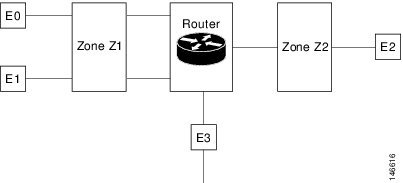
•![]() Interfaces E0 and E1 are members of security zone Z1.
Interfaces E0 and E1 are members of security zone Z1.
•![]() Interface E2 is a member of security zone Z2.
Interface E2 is a member of security zone Z2.
•![]() Interface E3 is not a member of any security zone.
Interface E3 is not a member of any security zone.
VRF Aware Cisco IOS XE Firewall Deployment
A firewall can be deployed at many points within the network to protect VPN sites from Shared Service (or the Internet) and vice versa. The following firewall deployments are described:
•![]() Distributed Network Inclusion of VRF Aware Cisco IOS Firewall
Distributed Network Inclusion of VRF Aware Cisco IOS Firewall
•![]() Hub-and-Spoke Network Inclusion of VRF Aware Cisco IOS XE Firewall
Hub-and-Spoke Network Inclusion of VRF Aware Cisco IOS XE Firewall
Distributed Network Inclusion of VRF Aware Cisco IOS Firewall
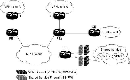
The Figure 4 illustrates a typical situation in which an SP offers firewall services to VPN customers VPN1 and VPN2, thereby protecting VPN sites from the external network (for example, shared services and the Internet) and vice versa.
Figure 4 Distributed Network
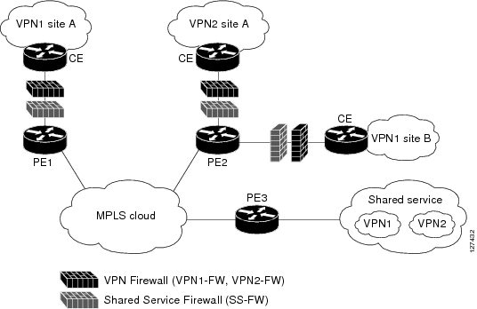
In this example, VPN1 has two sites, Site A and Site B, that span across the MPLS core. Site A is connected to PE1, and Site B is connected to PE2. VPN2 has only one site that is connected to PE2. Each VPN has a VLAN segment in the shared service that is connected to the corresponding VLAN subinterface on PE3.
Each of the VPNs (VPN1 and VPN2) has two firewall rules--one to protect the VPN site from the shared service and another to protect the shared service from the VPN site. The firewall that protects the VPN site from the shared service is called the VPN firewall, and the firewall that protects the shared service from the VPN site is called the Shared Service firewall. Both the firewall rules are applied on the VRF interface of each ingress PE that is connected to the VPN site. The VPN firewall rule is applied in the ingress direction, because the VRF interface is ingress to the VPN site; and the Shared Service Firewall rule is applied in the egress direction, because the VRF interface is egress to the shared service.
The benefits of using a distributed network are as follows:
•![]() Because the firewall deployment is distributed across an MPLS cloud, the firewall processing load is distributed to all ingress PEs.
Because the firewall deployment is distributed across an MPLS cloud, the firewall processing load is distributed to all ingress PEs.
•![]() The shared service is protected from VPN sites at the ingress PE, and hence malicious packets from VPN sites will be filtered at the ingress PE before they enter the MPLS cloud.
The shared service is protected from VPN sites at the ingress PE, and hence malicious packets from VPN sites will be filtered at the ingress PE before they enter the MPLS cloud.
•![]() VPN firewall features can be deployed in the ingress direction.
VPN firewall features can be deployed in the ingress direction.
Hub-and-Spoke Network Inclusion of VRF Aware Cisco IOS XE Firewall
Figure 5 The figure below illustrates a hub-and-spoke network where the firewalls for all VPN sites are applied on the egress PE router, PE3, which is connected to the shared service.
Figure 5 Hub-and-Spoke Network
Typically each VPN has a VLAN and/or VRF subinterface connected to the Shared Service. When a packet arrives from an MPLS interface, the inner tag represents the VPN-ID. MPLS routes the packet to the corresponding subinterface that is connected to Shared Service.
Typically, each VPN has a VLAN and/or a VRF subinterface that is connected to the shared service. When a packet arrives at an MPLS interface, MPLS routes the packet to the corresponding subinterface that is connected to the shared service. The firewall policies on each VPN are applied on the corresponding subinterface (VRF interface) as shown in the above figure. The VPN firewall rule is applied in the egress direction because the subinterface is egress to the VPN site. And the Shared Service firewall rule is applied in the ingress direction because the subinterface is ingress to the shared service.
The benefits of a hub-and-spoke network are as follows:
•![]() Because the firewall deployment is centralized to the egress PE (PE3), deploying and managing the firewall is easy.
Because the firewall deployment is centralized to the egress PE (PE3), deploying and managing the firewall is easy.
•![]() The Shared Service firewall features can be applied in the ingress direction.
The Shared Service firewall features can be applied in the ingress direction.
•![]() The VPN site is protected from the shared service at the egress PE, and hence malicious packets from the shared service are filtered at the PE before they enter the MPLS cloud.
The VPN site is protected from the shared service at the egress PE, and hence malicious packets from the shared service are filtered at the PE before they enter the MPLS cloud.
How to Configure VRF Aware Cisco XE IOS Firewall
•![]() Defining VRFs, Class Maps, and Policy Maps (required)
Defining VRFs, Class Maps, and Policy Maps (required)
•![]() Defining Zones and Zone Pairs (required)
Defining Zones and Zone Pairs (required)
•![]() Applying Zones to Interfaces and Defining Routes (required)
Applying Zones to Interfaces and Defining Routes (required)
Defining VRFs, Class Maps, and Policy Maps
SUMMARY STEPS
1. ![]() enable
enable
2. ![]() configure terminal
configure terminal
3. ![]() ip vrf vrf-name
ip vrf vrf-name
4. ![]() rd route-distinguisher
rd route-distinguisher
5. ![]() route-target export route-target-ext-community
route-target export route-target-ext-community
6. ![]() route-target import route-target-ext-community
route-target import route-target-ext-community
7. ![]() exit
exit
8. ![]() class-map type inspect match-any class-map-name
class-map type inspect match-any class-map-name
9. ![]() match protocol tcp
match protocol tcp
10. ![]() match protocol h323
match protocol h323
11. ![]() exit
exit
12. ![]() policy-map type inspect policy-map-name
policy-map type inspect policy-map-name
13. ![]() class type inspect class-map-name
class type inspect class-map-name
14. ![]() inspect [parameter-map-name]
inspect [parameter-map-name]
15. ![]() exit
exit
16. ![]() class class-default
class class-default
17. ![]() end
end
DETAILED STEPS
Defining Zones and Zone Pairs
SUMMARY STEPS
1. ![]() enable
enable
2. ![]() configure terminal
configure terminal
3. ![]() zone security security-zone-name
zone security security-zone-name
4. ![]() exit
exit
5. ![]() zone security security-zone-name
zone security security-zone-name
6. ![]() exit
exit
7. ![]() zone-pair security zone-pair-name source source-zone destination destination-zone
zone-pair security zone-pair-name source source-zone destination destination-zone
8. ![]() service-policy type inspect policy-map-name
service-policy type inspect policy-map-name
9. ![]() end
end
DETAILED STEPS
Applying Zones to Interfaces and Defining Routes
SUMMARY STEPS
1. ![]() enable
enable
2. ![]() configure terminal
configure terminal
3. ![]() interface type number
interface type number
4. ![]() ip vrf forwarding name
ip vrf forwarding name
5. ![]() ip address ip-address mask
ip address ip-address mask
6. ![]() zone-member security zone-name
zone-member security zone-name
7. ![]() negotiation auto
negotiation auto
8. ![]() exit
exit
9. ![]() interface type number
interface type number
10. ![]() ip address ip-address mask
ip address ip-address mask
11. ![]() zone-member security zone-name
zone-member security zone-name
12. ![]() negotiation auto
negotiation auto
13. ![]() exit
exit
14. ![]() ip route vrf vrf-name destination-ip-address destination-prefix interface-type number [global]
ip route vrf vrf-name destination-ip-address destination-prefix interface-type number [global]
15. ![]() end
end
DETAILED STEPS
Configuration Examples for VRF Aware Cisco IOS XE Firewall
•![]() Example: Defining VRFs, Class Maps, and Policy Maps
Example: Defining VRFs, Class Maps, and Policy Maps
•![]() Example: Defining Zones and Zone Pairs
Example: Defining Zones and Zone Pairs
•![]() Example: Applying Zones to Interfaces and Defining Routes
Example: Applying Zones to Interfaces and Defining Routes
Example: Defining VRFs, Class Maps, and Policy Maps
Router# configure terminal
Router(config)# ip vrf vrf1
Router(config-vrf)# rd 10:1
Router(config-vrf)# route-target export 10:1
Router(config-vrf)# route-target import 10:1
Router(config-vrf)# exit
Router(config)# class-map type inspect match-any class-map1
Router(config-cmap)# match protocol tcp
Router(config-cmap)# match protocol h323
Router(config-cmap)# exit
Router(config)# policy-map type inspect global-vpn1-pmap
Router(config-pmap)# class type inspect match-acl-111
Router(config-pmap-c)# inspect match-acl-111
Router(config-pmap-c)# exit
Router(config-pmap)# class class-default
Router(config-pmap)# end
Example: Defining Zones and Zone Pairs
Router# configure terminal
Router(config)# zone security vpn1-zone
Router(config-sec-zone)# exit
Router(config)# zone security global-zone
Router(config-sec-zone)# exit
Router(config)# zone-pair security vpn1-global-zone-pair source vpn1-zone destination
global-zone
Router(config-sec-zone-pair)# service-policy type inspect vpn1-global-pmap
Router(config-sec-zone-pair)# end
Example: Applying Zones to Interfaces and Defining Routes
Router# configure terminal
Router(config)# interface gigabitethernet 0/0/0
Router(config-if)# ip vrf forwarding vrf1
Router(config-if)# ip address 10.1.1.1 255.255.255.0
Router(config-if)# zone-member security vpn1-zone
Router(config-if)# negotiation auto
Router(config-if)# exit
Router(config)# interface gigabitethernet 1/1/1
Router(config-if)# ip address 10.111.111.111 255.255.255.0
Router(config-if)# zone-member security global-zone
Router(config-if)# negotiation auto
Router(config-if)# exit
Router(config)# ip route vrf vpn1 10.111.111.0 255.255.255.0 gigabitethernet 1/1/1 global
Router(config)# end
Additional References
Related Documents
|
|
|
|---|---|
Cisco IOS commands |
|
Security commands |
• • • |
NAT |
|
MPLS VPN |
|
Zone-based Policy Firewall |
Standards and RFCs
|
|
|
|---|---|
No new or modified standards or RFCs are supported, and support for existing standards has not been modified. |
— |
MIBs
Technical Assistance
Feature Information for VRF Aware Cisco IOS XE Firewall
Table 1 lists the features in this module and provides links to specific configuration information.
Use Cisco Feature Navigator to find information about platform support and software image support. Cisco Feature Navigator enables you to determine which software images support a specific software release, feature set, or platform. To access Cisco Feature Navigator, go to http://www.cisco.com/go/cfn. An account on Cisco.com is not required.
|
Note |
Glossary
CE router—customer edge router. A router that is part of a customer network and that interfaces to a provider edge (PE) router.
data authentication—Refers to one or both of the following: data integrity, which verifies that data has not been altered, or data origin authentication, which verifies that the data was actually sent by the claimed sender.
data confidentiality—A security service where the protected data cannot be observed.
edge router—A router that turns unlabeled packets into labeled packets, and vice versa.
firewall—A router or access server, or several routers or access servers, designated as a buffer between any connected public networks and a private network. A firewall router uses access lists and other methods to ensure the security of the private network.
IPsec—IP Security Protocol. A framework of open standards developed by IETF. IPsec provides security for transmission of sensitive data over unprotected networks such as the Internet.
managed security services—A comprehensive set of programs that enhance service providers' abilities to meet the growing demands of their enterprise customers. Services based on Cisco solutions include managed firewall, managed VPN (network based and premises based), and managed intrusion detection.
NAT—Network Address Translation. Translates a private IP address used inside the corporation to a public, routable address for use outside of the corporation, such as the Internet. NAT is considered a one-to-one mapping of addresses from private to public.
PE router—provider edge router. A router that is part of a service provider's network and is connected to a customer edge (CE) router.
UDP— User Datagram Protocol. Connectionless transport layer protocol in the TCP/IP protocol stack. UDP is a simple protocol that exchanges datagrams without acknowledgments or guaranteed delivery, requiring that error processing and retransmission be handled by other protocols.
VPN—Virtual Private Network. Enables IP traffic to travel securely over a public TCP/IP network by encrypting all traffic from one network to another. A VPN uses "tunneling" to encrypt all information at the IP level.
vrf—A VPN routing/forwarding instance. A VRF consists of an IP routing table, a derived forwarding table, a set of interfaces that use the forwarding table, and a set of rules and routing protocols that determine what goes into the forwarding table. In general, a VRF includes the routing information that defines a customer VPN site that is attached to a provider edge (PE) router.
VRF table—A table that stores routing data for each VPN. The VRF table defines the VPN membership of a customer site attached to the network access server (NAS). Each VRF table comprises an IP routing table, a derived Cisco Express Forwarding table, and guidelines and routing protocol parameters that control the information that is included in the routing table.
 Feedback