- MPLS LDP Graceful Restart
- NSF/SSO - MPLS LDP and LDP Graceful Restart
- ISSU MPLS Clients
- MPLS Traffic Engineering�RSVP Graceful Restart
- NSF/SSO�MPLS TE and RSVP Graceful Restart
- Configuring NSF/SSO�MPLS VPN
- SSO and ISSU - MPLS VPN 6VPE and 6PE
- AToM Graceful Restart
- NSF/SSO�Any Transport over MPLS and AToM Graceful Restart
- L2VPN Pseudowire Redundancy
MPLS: High Availability Configuration Guide, Cisco IOS XE Release 3S
Bias-Free Language
The documentation set for this product strives to use bias-free language. For the purposes of this documentation set, bias-free is defined as language that does not imply discrimination based on age, disability, gender, racial identity, ethnic identity, sexual orientation, socioeconomic status, and intersectionality. Exceptions may be present in the documentation due to language that is hardcoded in the user interfaces of the product software, language used based on RFP documentation, or language that is used by a referenced third-party product. Learn more about how Cisco is using Inclusive Language.
- Updated:
- April 14, 2009
Chapter: L2VPN Pseudowire Redundancy
- Finding Feature Information
- Contents
- Prerequisites for L2VPN Pseudowire Redundancy
- Restrictions for L2VPN Pseudowire Redundancy
- Information About L2VPN Pseudowire Redundancy
- How to Configure L2VPN Pseudowire Redundancy
- Configuration Examples for L2VPN Pseudowire Redundancy
- Additional References
- Feature Information for L2VPN Pseudowire Redundancy
L2VPN Pseudowire Redundancy
The L2VPN Pseudowire Redundancy feature enables you to configure your network to detect a failure in the network and reroute the Layer 2 (L2) service to another endpoint that can continue to provide service. This feature provides the ability to recover from a failure either of the remote provider edge (PE) router or of the link between the PE and customer edge (CE) routers. This feature also provides the ability to set up multiple backup pseudowires.
Finding Feature Information
For the latest feature information and caveats, see the release notes for your platform and software release. To find information about the features documented in this module, and to see a list of the releases in which each feature is supported, see the "Feature Information for L2VPN Pseudowire Redundancy" section.
Use Cisco Feature Navigator to find information about platform support and Cisco IOS XE software image support. To access Cisco Feature Navigator, go to http://www.cisco.com/go/cfn. An account on Cisco.com is not required.
Contents
•![]() Prerequisites for L2VPN Pseudowire Redundancy
Prerequisites for L2VPN Pseudowire Redundancy
•![]() Restrictions for L2VPN Pseudowire Redundancy
Restrictions for L2VPN Pseudowire Redundancy
•![]() Information About L2VPN Pseudowire Redundancy
Information About L2VPN Pseudowire Redundancy
•![]() How to Configure L2VPN Pseudowire Redundancy
How to Configure L2VPN Pseudowire Redundancy
•![]() Configuration Examples for L2VPN Pseudowire Redundancy
Configuration Examples for L2VPN Pseudowire Redundancy
•![]() Feature Information for L2VPN Pseudowire Redundancy
Feature Information for L2VPN Pseudowire Redundancy
Prerequisites for L2VPN Pseudowire Redundancy
•![]() This feature module requires that you understand how to configure basic L2 Virtual Private Networks (VPNs).
This feature module requires that you understand how to configure basic L2 Virtual Private Networks (VPNs).
•![]() The L2VPN Pseudowire Redundancy feature requires that the following mechanisms be in place to enable you to detect a failure in the network:
The L2VPN Pseudowire Redundancy feature requires that the following mechanisms be in place to enable you to detect a failure in the network:
–![]() Label-switched paths (LSP) Ping/Traceroute and Any Transport over MPLS Virtual Circuit Connection Verification (AToM VCCV)
Label-switched paths (LSP) Ping/Traceroute and Any Transport over MPLS Virtual Circuit Connection Verification (AToM VCCV)
–![]() Local Management Interface (LMI)
Local Management Interface (LMI)
–![]() Operation, Administration, and Maintenance (OAM)
Operation, Administration, and Maintenance (OAM)
Restrictions for L2VPN Pseudowire Redundancy
•![]() The default Label Distribution Protocol (LDP) session hold-down timer will enable the software to detect failures in about 180 seconds. That time can be configured so that the software can detect failures more quickly. See the mpls ldp holdtime command for more information.
The default Label Distribution Protocol (LDP) session hold-down timer will enable the software to detect failures in about 180 seconds. That time can be configured so that the software can detect failures more quickly. See the mpls ldp holdtime command for more information.
•![]() Pseudowire redundancy is not supported for Layer 2 Tunnel Protocol Version 3 (L2TPv3) xconnect configurations.
Pseudowire redundancy is not supported for Layer 2 Tunnel Protocol Version 3 (L2TPv3) xconnect configurations.
•![]() The primary and backup pseudowires must run the same type of transport service. The primary and backup pseudowires must be configured with AToM.
The primary and backup pseudowires must run the same type of transport service. The primary and backup pseudowires must be configured with AToM.
•![]() Only static, on-box provisioning is supported in this release.
Only static, on-box provisioning is supported in this release.
•![]() If you use L2VPN Pseudowire Redundancy with L2VPN Interworking, the interworking method must be the same for the primary and backup pseudowires.
If you use L2VPN Pseudowire Redundancy with L2VPN Interworking, the interworking method must be the same for the primary and backup pseudowires.
•![]() L2VPN Pseudowire Redundancy does support setting the experimental (EXP) bit on the Multiprotocol Label Switching (MPLS) pseudowire.
L2VPN Pseudowire Redundancy does support setting the experimental (EXP) bit on the Multiprotocol Label Switching (MPLS) pseudowire.
•![]() L2VPN Pseudowire Redundancy does not support different pseudowire encapsulation types on the MPLS pseudowire.
L2VPN Pseudowire Redundancy does not support different pseudowire encapsulation types on the MPLS pseudowire.
•![]() The mpls l2transport route command is not supported. Use the xconnect command instead.
The mpls l2transport route command is not supported. Use the xconnect command instead.
•![]() The ability to have the backup pseudowire fully operational at the same time that the primary pseudowire is operational is not supported. The backup pseudowire becomes active only after the primary pseudowire fails.
The ability to have the backup pseudowire fully operational at the same time that the primary pseudowire is operational is not supported. The backup pseudowire becomes active only after the primary pseudowire fails.
•![]() The AToM VCCV feature is supported only on the active pseudowire.
The AToM VCCV feature is supported only on the active pseudowire.
•![]() In Cisco IOS XE Release 2.3, only one backup pseudowire is supported. In Cisco IOS XE Release 2.4 and later releases, up to three backup pseudowires are supported.
In Cisco IOS XE Release 2.3, only one backup pseudowire is supported. In Cisco IOS XE Release 2.4 and later releases, up to three backup pseudowires are supported.
•![]() A primary pseudowire in L2VPN Pseudowire Redundancy feature cannot be backed up by a Layer 2 local switched interface.
A primary pseudowire in L2VPN Pseudowire Redundancy feature cannot be backed up by a Layer 2 local switched interface.
•![]() In Cisco IOS XE Release 2.4, the L2VPN Pseudowire Redundancy: Multiple Backup Pseudowires feature supports only ATM interfaces.
In Cisco IOS XE Release 2.4, the L2VPN Pseudowire Redundancy: Multiple Backup Pseudowires feature supports only ATM interfaces.
Information About L2VPN Pseudowire Redundancy
•![]() Introduction to L2VPN Pseudowire Redundancy
Introduction to L2VPN Pseudowire Redundancy
Introduction to L2VPN Pseudowire Redundancy
L2VPNs can provide pseudowire resiliency through their routing protocols. When connectivity between end-to-end PE routers fails, an alternative path to the directed LDP session and the user data can take over. However, there are some parts of the network where this rerouting mechanism does not protect against interruptions in service. Figure 1 shows those parts of the network that are vulnerable to an interruption in service.
Figure 1 Points of Potential Failure in an L2VPN Network
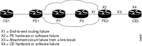
The L2VPN Pseudowire Redundancy feature provides the ability to ensure that the CE2 router in Figure 1 can always maintain network connectivity, even if one or all the failures in the figure occur.
The L2VPN Pseudowire Redundancy feature enables you to set up backup pseudowires. You can configure the network with redundant pseudowires (PWs) and redundant network elements, which are shown in Figure 2, Figure 3, and Figure 4.
Figure 2 shows a network with redundant pseudowires and redundant attachment circuits.
Figure 2 L2 VPN Network with Redundant PWs and Attachment Circuits
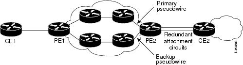
Figure 3 shows a network with redundant pseudowires, attachment circuits, and CE routers.
Figure 3 L2 VPN Network with Redundant PWs, Attachment Circuits, and CE Routers
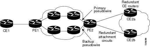
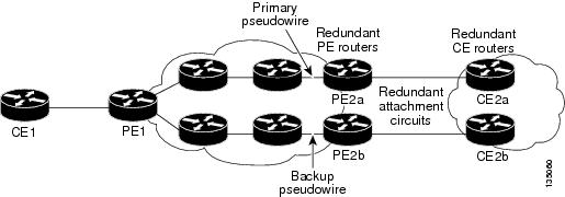
Figure 4 shows a network with redundant pseudowires, attachment circuits, CE routers, and PE routers.
Figure 4 L2 VPN Network with Redundant PWs, Attachment Circuits, CE Routers, and PE Routers
How to Configure L2VPN Pseudowire Redundancy
The L2VPN Pseudowire Redundancy feature enables you to configure a backup pseudowire in case the primary pseudowire fails. When the primary pseudowire fails, the PE router can switch to the backup pseudowire. You can have the primary pseudowire resume operation after it comes back up.

Note ![]() In Cisco IOS XE Release 2.3, only one backup pseudowire is supported. In Cisco IOS XE Release 2.4 and later releases, up to three backup pseudowires are supported.
In Cisco IOS XE Release 2.3, only one backup pseudowire is supported. In Cisco IOS XE Release 2.4 and later releases, up to three backup pseudowires are supported.
•![]() Configuring the Pseudowire Attributes (required)
Configuring the Pseudowire Attributes (required)
•![]() Configuring a Single Backup Pseudowire (required)
Configuring a Single Backup Pseudowire (required)
•![]() Configuring Multiple Backup Pseudowires (required)
Configuring Multiple Backup Pseudowires (required)
•![]() Forcing a Manual Switchover to the Backup Pseudowire VC (optional)
Forcing a Manual Switchover to the Backup Pseudowire VC (optional)
•![]() Verifying the L2VPN Pseudowire Redundancy Configuration (optional)
Verifying the L2VPN Pseudowire Redundancy Configuration (optional)
Configuring the Pseudowire Attributes
The successful transmission of the Layer 2 frames between PE routers is due to the configuration of the PE routers. You set up the connection, called a pseudowire, between the routers.
The pseudowire-class configuration group specifies the characteristics of the tunneling mechanism, which are:
•![]() Encapsulation type
Encapsulation type
•![]() Control protocol
Control protocol
•![]() Payload-specific options
Payload-specific options
You must specify the encapsulation mpls command as part of the pseudowire class for the AToM VCs to work properly. If you omit the encapsulation mpls command as part of the xconnect command, you receive the following error:
% Incomplete command.
Perform this task to configure a pseudowire class.
SUMMARY STEPS
1. ![]() enable
enable
2. ![]() configure terminal
configure terminal
3. ![]() pseudowire-class name
pseudowire-class name
4. ![]() encapsulation mpls
encapsulation mpls
5. ![]() interworking {ethernet | ip}
interworking {ethernet | ip}
DETAILED STEPS
Configuring a Single Backup Pseudowire
In Cisco IOS XE Release 2.3, only one backup pseudowire is supported. In Cisco IOS XE Release 2.4 and later releases, up to three backup pseudowires are supported. Use the following steps to configure a single backup pseudowire.
Prerequisites
For each transport type, the xconnect command is configured slightly differently. The following configuration steps use Ethernet VLAN over MPLS, which is configured in subinterface configuration mode. See Any Transport over MPLS to determine how to configure the xconnect command for other transport types.
SUMMARY STEPS
1. ![]() enable
enable
2. ![]() configure terminal
configure terminal
3. ![]() interface gigabitethernet slot/subslot/interface.[subinterface]
interface gigabitethernet slot/subslot/interface.[subinterface]
4. ![]() encapsulation dot1q vlan-id
encapsulation dot1q vlan-id
5. ![]() xconnect peer-router-id vcid {encapsulation mpls | pw-class pw-class-name}
xconnect peer-router-id vcid {encapsulation mpls | pw-class pw-class-name}
6. ![]() backup peer peer-router-ip-addr vcid [pw-class pw-class-name]
backup peer peer-router-ip-addr vcid [pw-class pw-class-name]
7. ![]() backup delay enable-delay {disable-delay | never}
backup delay enable-delay {disable-delay | never}
DETAILED STEPS
Configuring Multiple Backup Pseudowires
In Cisco IOS XE Release 2.4 and later releases, up to three backup pseudowires are supported. You can assign priorities to the backup pseudowires to specify which pseudowire to use first if the primary pseudowire fails. Use the following steps to configure multiple backup pseudowires.
Restrictions
In Cisco IOS XE Release 2.4, the L2VPN Pseudowire Redundancy: Multiple Backup Pseudowires feature supports only ATM interfaces.
SUMMARY STEPS
1. ![]() enable
enable
2. ![]() configure terminal
configure terminal
3. ![]() interface atm slot/port
interface atm slot/port
4. ![]() pvc vpi/vci l2transport
pvc vpi/vci l2transport
5. ![]() encapsulation layer-type
encapsulation layer-type
6. ![]() xconnect peer-router-id vcid {encapsulation mpls | pw-class pw-class-name}
xconnect peer-router-id vcid {encapsulation mpls | pw-class pw-class-name}
7. ![]() backup peer peer-router-ip-addr vcid [pw-class pw-class-name] [priority value]
backup peer peer-router-ip-addr vcid [pw-class pw-class-name] [priority value]
8. ![]() backup delay enable-delay {disable-delay | never}
backup delay enable-delay {disable-delay | never}
DETAILED STEPS
Forcing a Manual Switchover to the Backup Pseudowire VC
To force the router switch over to the backup or primary pseudowire, you can enter the xconnect backup force switchover command in privileged EXEC mode. You can specify either the interface of the primary attachment circuit (AC) to switch to or the IP-address and VC ID of the peer router.
A manual switchover can be made only if the interface or peer specified in the command is actually available and the xconnect will move to the fully active state when the command is entered.
SUMMARY STEPS
1. ![]() enable
enable
2. ![]() xconnect backup force-switchover interface {type number| peer ip-address vcid}
xconnect backup force-switchover interface {type number| peer ip-address vcid}
DETAILED STEPS
Verifying the L2VPN Pseudowire Redundancy Configuration
SUMMARY STEPS
1. ![]() show mpls l2transport vc
show mpls l2transport vc
2. ![]() show xconnect all
show xconnect all
3. ![]() xconnect logging redundancy
xconnect logging redundancy
DETAILED STEPS
Step 1 ![]() show mpls l2transport vc
show mpls l2transport vc
In this example, the primary attachment circuit is up. The backup attachment circuit is available, but not currently selected. The show output displays as follows:
Router# show mpls l2transport vc
Local intf Local circuit Dest address VC ID Status
------------- ----------------------- --------------- ---------- ----------
Fe0/0/0.1 Fe VLAN 101 10.0.0.2 101 UP
Fe0/0/0.1 Fe VLAN 101 10.0.0.3 201 STANDBY
Router# show mpls l2transport vc detail
Local interface: fe0/0/0.1 up, line protocol up, fe VLAN 101 up
Destination address 10.0.0.2 VC ID: 101, VC status UP
.
.
.
Local interface: fe0/0/0.1 down, line protocol down, fe VLAN 101 down
Destination address 10.0.0.3 VC ID: 201, VC status down
.
.
.
Step 2 ![]() show xconnect all
show xconnect all
In this example, the topology is Attachment Circuit 1 to Pseudowire 1 with a Pseudowire 2 as a backup:
Router# show xconnect all
Legend: XC ST=Xconnect State, S1=Segment1 State, S2=Segment2 State
UP=Up, DN=Down, AD=Admin Down, IA=Inactive, NH=No Hardware
XC ST Segment 1 S1 Segment 2 S2
------+---------------------------------+--+---------------------------------+--
UP pri ac fe0/0/0(FastEthernet) UP mpls 10.55.55.2:1000 UP
IA sec ac fe0/0/0(FastEthernet) UP mpls 10.55.55.3:1001 DN
In this example, the topology is Attachment Circuit 1 to Attachment Circuit 2 with a Pseudowire backup for Attachment Circuit 2:
Router# show xconnect all
Legend: XC ST=Xconnect State, S1=Segment1 State, S2=Segment2 State
UP=Up, DN=Down, AD=Admin Down, IA=Inactive, NH=No Hardware
XC ST Segment 1 S1 Segment 2 S2
------+---------------------------------+--+---------------------------------+--
UP pri ac Se6/0/0:150(FR DLCI) UP ac Se8/0:150(FR DLCI) UP
IA sec ac Se6/0/0:150(FR DLCI) UP mpls 10.55.55.3:7151 DN
Step 3 ![]() xconnect logging redundancy
xconnect logging redundancy
In addition to the show mpls l2transport vc command and the show xconnect command, you can use the xconnect logging redundancy command to track the status of the xconnect redundancy group:
Router(config)# xconnect logging redundancy
When this command is configured, the following messages will be generated during switchover events:
Activating the primary member:
00:01:07: %XCONNECT-5-REDUNDANCY: Activating primary member 10.55.55.2:1000
Activating the backup member:
00:01:05: %XCONNECT-5-REDUNDANCY: Activating secondary member 10.55.55.3:1001
Configuration Examples for L2VPN Pseudowire Redundancy
The following sections show the L2VPN Pseudowire Redundancy feature examples. These configuration examples show how the L2VPN Pseudowire Redundancy feature can be configured with the AToM (like-to-like) and L2VPN Interworking features.
•![]() Example: L2VPN Pseudowire Redundancy and AToM (Like-to-Like)
Example: L2VPN Pseudowire Redundancy and AToM (Like-to-Like)
•![]() Example: L2VPN Pseudowire Redundancy and L2VPN Interworking
Example: L2VPN Pseudowire Redundancy and L2VPN Interworking
•![]() Example: L2VPN Pseudowire Redundancy—Multiple Backup Pseudowires
Example: L2VPN Pseudowire Redundancy—Multiple Backup Pseudowires
Each of the configuration examples refers to one of the following pseudowire classes:
•![]() AToM (like-to-like) pseudowire class:
AToM (like-to-like) pseudowire class:
pseudowire-class mpls
encapsulation mpls
•![]() L2VPN IP interworking:
L2VPN IP interworking:
pseudowire-class mpls-ip
encapsulation mpls
interworking ip
Example: L2VPN Pseudowire Redundancy and AToM (Like-to-Like)
The following example shows a High-Level Data Link Control (HDLC) attachment circuit xconnect with a backup pseudowire:
interface Serial4/0/0
xconnect 10.55.55.2 4000 pw-class mpls
backup peer 10.55.55.3 4001 pw-class mpls
The following example shows a Frame Relay attachment circuit xconnect with a backup pseudowire:
connect fr-fr-pw Serial6/0/0 225 l2transport
xconnect 10.55.55.2 5225 pw-class mpls
backup peer 10.55.55.3 5226 pw-class mpls
Example: L2VPN Pseudowire Redundancy and L2VPN Interworking
The following example shows a Fast Ethernet attachment circuit xconnect with L2VPN IP interworking and a backup pseudowire:
interface FastEthernet0/0/0
xconnect 10.55.55.2 1000 pw-class mpls-ip
backup peer 10.55.55.3 1001 pw-class mpls-ip
The following example shows an Fast Ethernet VLAN attachment circuit xconnect with L2VPN IP interworking and a backup pseudowire:
interface FastEthernet1/0/0.1
encapsulation dot1Q 200
no ip directed-broadcast
xconnect 10.55.55.2 5200 pw-class mpls-ip
backup peer 10.55.55.3 5201 pw-class mpls-ip
Example: L2VPN Pseudowire Redundancy—Multiple Backup Pseudowires
The following example shows a pseudowire with two backup pseudowires:
interface ATM4/0.1 point-to-point
pvc 0/100 l2transport
encapsulation aal5snap
xconnect 10.1.1.1 100 pw-class mpls
backup peer 10.1.1.1 101
backup peer 10.10.1.1 110 priority 2
backup peer 10.20.1.1 111 priority 9
Additional References
Related Documents
|
|
|
|---|---|
Cisco IOS commands |
|
Description of commands associated with MPLS and MPLS applications |
|
Any Transport over MPLS |
|
High Availability for AToM |
Standards
|
|
|
|---|---|
No new or modified standards are supported, and support for existing standards has not been modified by this feature. |
— |
MIBs
RFCs
|
|
|
|---|---|
No new or modified RFCs are supported, and support for existing RFCs has not been modified. |
— |
Technical Assistance
Feature Information for L2VPN Pseudowire Redundancy
Table 1 lists the release history for this feature and provides links to specific configuration information.
Use Cisco Feature Navigator to find information about platform support and software image support. Cisco Feature Navigator enables you to determine which Cisco IOS XE software images support a specific software release, feature set, or platform. To access Cisco Feature Navigator, go to http://www.cisco.com/go/cfn. An account on Cisco.com is not required.
Note ![]() Table 1 lists only the Cisco IOS XE software release that introduced support for a given feature in a given Cisco IOS XE software release train. Unless noted otherwise, subsequent releases of that Cisco IOS XE software release train also support that feature.
Table 1 lists only the Cisco IOS XE software release that introduced support for a given feature in a given Cisco IOS XE software release train. Unless noted otherwise, subsequent releases of that Cisco IOS XE software release train also support that feature.
|
|
|
|
|---|---|---|
L2VPN Pseudowire Redundancy |
Cisco IOS XE Release 2.3 |
This feature enables you to set up your network to detect a failure in the network and reroute the Layer 2 service to another endpoint that can continue to provide service. The following sections provide information about this feature: • • • • • The following commands were introduced or modified: backup delay (L2VPN local switching), backup peer, show xconnect, xconnect backup force-switchover, xconnect logging redundancy. |
L2VPN Pseudowire Redundancy: Multiple Backup Pseudowires |
Cisco IOS XE Release 2.4 |
This feature enables multiple backup pseudowires. The following command was modified: backup peer. |
 Feedback