-
- Cisco Express Forwarding Features Roadmap
- Cisco Express Forwarding Overview
- Configuring Basic Cisco Express Forwarding for Improved Performance, Scalability, and Resiliency in Dynamic Networks
- Enabling or Disabling Cisco Express Forwarding or Distributed Cisco Express Forwarding to Customize Switching/Forwarding for Dynamic Networks
- Configuring a Load-Balancing Scheme for Cisco Express Forwarding Traffic
- Configuring Epochs to Clear and Rebuild Cisco Express Forwarding and Adjacency Tables
- Configuring Cisco Express Forwarding Consistency Checkers for Route Processors and Line Cards
- Configuring Cisco Express Forwarding Network Accounting
- Customizing the Display of Cisco Express Forwarding Event Trace Messages
- Cisco Express Forwarding - SNMP CEF-MIB Support
IP Switching Configuration Guide, Cisco IOS XE Release 3S
Bias-Free Language
The documentation set for this product strives to use bias-free language. For the purposes of this documentation set, bias-free is defined as language that does not imply discrimination based on age, disability, gender, racial identity, ethnic identity, sexual orientation, socioeconomic status, and intersectionality. Exceptions may be present in the documentation due to language that is hardcoded in the user interfaces of the product software, language used based on RFP documentation, or language that is used by a referenced third-party product. Learn more about how Cisco is using Inclusive Language.
- Updated:
- May 5, 2009
Chapter: Configuring Cisco Express Forwarding Network Accounting
- Finding Feature Information
- Contents
- Prerequisites for Configuring Cisco Express Forwarding Network Accounting
- Information About Configuring Cisco Express Forwarding Network Accounting
- Cisco Platform Support for Central Cisco Express Forwarding and Distributed Cisco Express Forwarding
- Traffic Matrix Statistics That You Can Collect and View
- TMS and Cisco Express Forwarding Nonrecursive Accounting in Backbone Routers
- How Backbone Routers Collect TMS
- TMS Viewing Options
- Statistics in the timestats_ascii File
- Statistics in the tmsasinfo File
- How to Configure Cisco Express Forwarding Network Accounting
- Configuring Cisco Express Forwarding Network Accounting
- Enabling a Backbone Router to Collect TMS
- Interpreting the Statistics in the tmstats_ascii File
- Viewing Information in the tmsasinfo File: BGP Neighbor Autonomous Systems for IGP Destinations
- Verifying Cisco Express Forwarding Network Accounting Information
- Configuration Examples for Configuring Cisco Express Forwarding Network Accounting
- Additional References
- Feature Information for Configuring Cisco Express Forwarding Network Accounting
- Glossary
Configuring Cisco Express Forwarding Network Accounting
This module contains information about and instructions for configuring network accounting for Cisco Express Forwarding. Accounting produces the statistics that enable you to better understand Cisco Express Forwarding patterns in your network. For example, you might want to find out the number of packets and bytes switched to a destination or the number of packets switched through a destination.
Cisco Express Forwarding is an advanced Layer 3 IP switching technology. It optimizes network performance and scalability for all kinds of networks: those that carry small amounts of traffic and those that carry large amounts of traffic in complex patterns, such as the Internet and networks characterized by intensive web-based applications or interactive sessions.
Finding Feature Information
For the latest feature information and caveats, see the release notes for your platform and software release. To find information about the features documented in this module, and to see a list of the releases in which each feature is supported, see the "Feature Information for Configuring Cisco Express Forwarding Network Accounting" section.
Use Cisco Feature Navigator to find information about platform support and Cisco IOS XE software image support. To access Cisco Feature Navigator, go to http://www.cisco.com/go/cfn. An account on Cisco.com is not required.
Contents
•![]() Prerequisites for Configuring Cisco Express Forwarding Network Accounting
Prerequisites for Configuring Cisco Express Forwarding Network Accounting
•![]() Information About Configuring Cisco Express Forwarding Network Accounting
Information About Configuring Cisco Express Forwarding Network Accounting
•![]() How to Configure Cisco Express Forwarding Network Accounting
How to Configure Cisco Express Forwarding Network Accounting
•![]() Configuration Examples for Configuring Cisco Express Forwarding Network Accounting
Configuration Examples for Configuring Cisco Express Forwarding Network Accounting
•![]() Feature Information for Configuring Cisco Express Forwarding Network Accounting
Feature Information for Configuring Cisco Express Forwarding Network Accounting
Prerequisites for Configuring Cisco Express Forwarding Network Accounting
Cisco Express Forwarding must be up and running on the networking device before you can configure network accounting for Cisco Express Forwarding. See the "Cisco Platform Support for Central Cisco Express Forwarding and Distributed Cisco Express Forwarding" section for information on how to determine if Cisco Express Forwarding is enabled on your networking device.
Information About Configuring Cisco Express Forwarding Network Accounting
Before you configure Cisco Express Forwarding network accounting, you should understand the following information:
•![]() Cisco Platform Support for Central Cisco Express Forwarding and Distributed Cisco Express Forwarding
Cisco Platform Support for Central Cisco Express Forwarding and Distributed Cisco Express Forwarding
•![]() Traffic Matrix Statistics That You Can Collect and View
Traffic Matrix Statistics That You Can Collect and View
•![]() TMS and Cisco Express Forwarding Nonrecursive Accounting in Backbone Routers
TMS and Cisco Express Forwarding Nonrecursive Accounting in Backbone Routers
•![]() How Backbone Routers Collect TMS
How Backbone Routers Collect TMS
•![]() Statistics in the timestats_ascii File
Statistics in the timestats_ascii File
•![]() Statistics in the tmsasinfo File
Statistics in the tmsasinfo File
For links to information about other Cisco Express Forwarding and distributed Cisco Express Forwarding features that you can configure, go to the "Additional References" section.
Cisco Platform Support for Central Cisco Express Forwarding and Distributed Cisco Express Forwarding
Cisco Express Forwarding is enable by default on the Cisco ASR 1000 Series Aggregation Services Routers.
To find out if Cisco Express Forwarding is enabled on your platform, enter the show ip cef command. If Cisco Express Forwarding is enabled, you receive output that looks like this:
Router# show ip cef
Prefix Next Hop Interface
[...]
10.2.61.8/24 192.168.100.1 FastEthernet1/0/0
192.168.101.1 FastEthernet2/1/0
[...]
If Cisco Express Forwarding is not enabled on your platform, the output for the show ip cef command looks like this:
Router# show ip cef
%CEF not running
Distributed Cisco Express Forwarding is enabled by default on the Cisco ASR 1000 Series Aggregation Services Routers. When distributed Cisco Express Forwarding is enabled on your platform, the line cards perform the express forwarding.
If Cisco Express Forwarding is not enabled on your platform, use the ip cef command to enable (central) Cisco Express Forwarding or the ip cef distributed command to enable distributed Cisco Express Forwarding.
Central Cisco Express Forwarding or distributed Cisco Express Forwarding has the following restrictions:
•![]() The Cisco ASR 1000 Series Routers operate only in distributed Cisco Express Forwarding mode. On these routers, you must not disable distributed Cisco Express Forwarding on an interface.
The Cisco ASR 1000 Series Routers operate only in distributed Cisco Express Forwarding mode. On these routers, you must not disable distributed Cisco Express Forwarding on an interface.
•![]() If you enable Cisco Express Forwarding and then create an access list that uses the log keyword, the packets that match the access list are not Cisco Express Forwarding switched. They are process switched. Logging disables Cisco Express Forwarding.
If you enable Cisco Express Forwarding and then create an access list that uses the log keyword, the packets that match the access list are not Cisco Express Forwarding switched. They are process switched. Logging disables Cisco Express Forwarding.
See the "Additional References" section for links to more information on the features and functionality of Cisco Express Forwarding.
Traffic Matrix Statistics That You Can Collect and View
The traffic matrix statistics (TMS) feature allows an administrator to gather the following data:
•![]() The number of packets and number of bytes that travel across the backbone from internal and external sources. The counts of packets and bytes are called TMS and are useful for determining how much traffic a backbone handles. You can analyze TMS using the following methods:
The number of packets and number of bytes that travel across the backbone from internal and external sources. The counts of packets and bytes are called TMS and are useful for determining how much traffic a backbone handles. You can analyze TMS using the following methods:
–![]() Collecting and viewing TMS through the application of the Network Data Analyzer (NDA)
Collecting and viewing TMS through the application of the Network Data Analyzer (NDA)
–![]() Reading the TMS that reside on the backbone router
Reading the TMS that reside on the backbone router
•![]() The neighbor autonomous systems of a Border Gateway Protocol (BGP) destination. You can view these systems by reading the tmasinfo_ascii file on the backbone router.
The neighbor autonomous systems of a Border Gateway Protocol (BGP) destination. You can view these systems by reading the tmasinfo_ascii file on the backbone router.
The following sections explain how to collect and view the TMS using the command-line interface (CLI) and the NDA. For detailed instructions on using the NDA, see the Network Data Analyzer Installation and User Guide.
TMS and Cisco Express Forwarding Nonrecursive Accounting in Backbone Routers
TMS enables an administrator to capture and analyze data on traffic entering a backbone that is running BGP. The TMS feature also allows an administrator to determine the neighbor autonomous systems of a BGP destination. TMS are counted during packet forwarding by Cisco Express Forwarding nonrecursive accounting.
By enabling a backbone router to gather TMS, you can determine the amount of traffic that enters the backbone from sites outside of the backbone. You can also determine the amount of traffic that is generated within the backbone. This information helps you optimize and manage traffic across the backbone.
The following paragraphs explain how Cisco Express Forwarding nonrecursive accounting aggregates packet statistics for Interior Gateway Protocol (IGP) routes and their dependent BGP routes.
A BGP network deployed by a service provider might have the following components:
•![]() IGP routes that describe the next hop to which traffic should be sent
IGP routes that describe the next hop to which traffic should be sent
•![]() BGP routes that specify an intermediate address to which traffic should be sent
BGP routes that specify an intermediate address to which traffic should be sent
The intermediate address specified for the BGP route might be several hops away from the provider edge (PE) router. The next hop for the BGP route is the next hop for the intermediate address of the BGP route. The BGP route is called recursive, because it points through an intermediate address to an IGP route that provides the next hop for forwarding. However, a route lookup results in a next hop that is not directly reachable, as is the case with the BGP route's intermediate address. A recursive lookup to an IGP route is used to decide how to reach the indirect next hop.
Cisco Express Forwarding represents IGP routes as nonrecursive entries and BGP routes as recursive entries that resolve through nonrecursive entries.
Cisco Express Forwarding nonrecursive accounting counts the packets for all of the Cisco Express Forwarding recursive entries (from BGP routes) that resolve through a Cisco Express Forwarding nonrecursive entry and the packets for the nonrecursive entry (from IGP routes). The number of packets is totalled in one location.
The packets forwarded based on a nonrecursive Cisco Express Forwarding entry can be split into two bins based on whether the input interface of the backbone router is configured as internal or external. Thus, all packets that arrive on external interfaces (external to the region of interest) and are forwarded based on a given IGP route (either directly or through a recursive BGP route) are counted together.
The following example shows how Cisco Express Forwarding nonrecursive accounting counts packets when BGP routes resolve to one IGP route and when they do not.
A multiaccess network access point (NAP) has BGP routes referring to hosts on the NAP network.
•![]() If the network is advertised as a single IGP route, all of the BGP routes to the various hosts at that NAP resolve to a single IGP route. Cisco Express Forwarding nonrecursive accounting counts the number of packets sent to all BGP destinations.
If the network is advertised as a single IGP route, all of the BGP routes to the various hosts at that NAP resolve to a single IGP route. Cisco Express Forwarding nonrecursive accounting counts the number of packets sent to all BGP destinations.
•![]() If a network administrator instead advertises individual host routes from the NAP network to the IGP, Cisco Express Forwarding nonrecursive accounting counts packets to those hosts separately.
If a network administrator instead advertises individual host routes from the NAP network to the IGP, Cisco Express Forwarding nonrecursive accounting counts packets to those hosts separately.
How Backbone Routers Collect TMS
You can determine the amount of traffic that enters the backbone from sites outside of the backbone if you enable a backbone router to gather TMS. You can also determine the amount of traffic that is generated within the backbone. This information helps you optimize and manage traffic across the backbone. Figure 1 and Figure 2 help illustrate the traffic statistics you can gather using TMS.
Figure 1 shows a sample network with backbone routers and links. The traffic that travels through the backbone is the area of interest for TMS collection. TMS are collected during packet forwarding. The backbone is represented by the darkly shaded routers and bold links. The lighter shaded and unshaded routers are outside the backbone.
Figure 1 Sample Network with Backbone Routers and Links
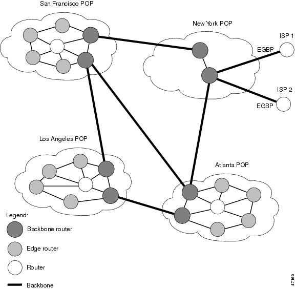
Figure 2 shows an exploded view of the backbone router that links the Los Angeles point of presence (POP) in Figure 1 to the Atlanta POP. The bold line represents the backbone link going to the Atlanta POP.
Figure 2 shows the following types of traffic that travel through the backbone router:
•![]() The dotted line marked A represents traffic entering the backbone from a router that is not part of the backbone. This is called external traffic.
The dotted line marked A represents traffic entering the backbone from a router that is not part of the backbone. This is called external traffic.
•![]() The dotted lines marked B and D represent traffic that is exiting the backbone. This is called internal traffic.
The dotted lines marked B and D represent traffic that is exiting the backbone. This is called internal traffic.
•![]() The dotted line marked C represents traffic that is not using the backbone and is not of interest to TMS.
The dotted line marked C represents traffic that is not using the backbone and is not of interest to TMS.
Figure 2 Types of Traffic That Travel Through a Backbone Router

You can determine the amount of traffic the backbone handles by enabling a backbone router to track the number of packets and bytes that travel through the backbone router. You can separate the traffic into the categories "internal" and "external." You separate the traffic by designating incoming interfaces on the backbone router as internal or external.
Once you enable a backbone router to collect TMS, the router starts counters, which dynamically update when network traffic passes through the backbone router. You can retrieve a snapshot of the TMS, either through a command to the backbone router or through the NDA.
External traffic (path A in Figure 2) is the most important for determining the amount of traffic that travels through a backbone router. Internal traffic (paths B and D in Figure 2) is useful for ensuring that you are capturing all of the TMS data. When you receive a snapshot of the TMS, the packets and bytes are displayed in internal and external categories.
TMS Viewing Options
Once TMS are collected, you have three options for viewing the data:
•![]() Viewing the data in a graphical format, using the NDA Display module. The Display module is useful for graphing the traffic matrix data and comparing statistics. See the "TMS Displayed with the NDA Display Module" section for more information.
Viewing the data in a graphical format, using the NDA Display module. The Display module is useful for graphing the traffic matrix data and comparing statistics. See the "TMS Displayed with the NDA Display Module" section for more information.
•![]() Entering the more system:vfiles/tmstats_ascii command on the backbone router. This command displays a TMS table. See the "Interpreting the Statistics in the tmstats_ascii File" section for more information.
Entering the more system:vfiles/tmstats_ascii command on the backbone router. This command displays a TMS table. See the "Interpreting the Statistics in the tmstats_ascii File" section for more information.
•![]() Entering the show ip cef command on the backbone router. This command displays nonrecursive accounting data for the backbone router. Included in the output are the numbers of packets and bytes of internal and external traffic that have been collected. See the "Nonrecursive Accounting Information Displayed with the show ip cef Command" section for more information.
Entering the show ip cef command on the backbone router. This command displays nonrecursive accounting data for the backbone router. Included in the output are the numbers of packets and bytes of internal and external traffic that have been collected. See the "Nonrecursive Accounting Information Displayed with the show ip cef Command" section for more information.
This section contains the following information about the display of accounting data:
•![]() TMS Displayed with the NDA Display Module
TMS Displayed with the NDA Display Module
•![]() Nonrecursive Accounting Information Displayed with the show ip cef Command
Nonrecursive Accounting Information Displayed with the show ip cef Command
TMS Displayed with the NDA Display Module
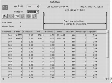
The NDA collects TMS from the backbone router and displays the data through the NDA Display module. The TMS can look similar to the data shown in Figure 3 and Figure 4. The display format depends on the aggregation scheme you select. See the Network Data Analyzer Installation and User Guide for more information.
(The view of data that the NDA Display module provides is wide. Slide the scroll bar to the right and left to see all of the data. Figure 3 and Figure 4 taken together show all of the columns of data.)
Figure 3 Displaying TMS Through the NDA (Part 1)
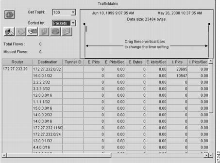
Figure 4 Displaying TMS Through the NDA (Part 2)
Nonrecursive Accounting Information Displayed with the show ip cef Command
You can use the show ip cef command to display nonrecursive accounting information, including the counts of internal and external packets and bytes that have traveled through the IP prefix address/mask (in the format a.b.c.d/len) for an IGP route. Here is an example that shows 0 packets and 0 bytes of external traffic and 1144 packets and 742 bytes of internal traffic for the router with the IP address 10.102.102.102:
Router# show ip cef 10.102.102.102
10.102.102.10/32, version 34, epoch 0, per-destination sharing
0 packets, 0 bytes
tag information set
local tag: 19
via 10.1.1.100, FastEthernet0/0/0, 0 dependencies
next hop 10.1.1.100, FastEthernet0/0/0
valid adjacency
tag rewrite with FE0/0/0, 10.1.1.100, tags imposed {17}
0 packets, 0 bytes switched through the prefix
tmstats: external 0 packets, 0 bytes
internal 1144 packets, 742 bytes
30 second output rate 0 Kbits/sec
Statistics in the timestats_ascii File
Before you perform the task to interpret the statistics in the tmstats_ascii file (an optional procedure described in the "Interpreting the Statistics in the tmstats_ascii File" section), you need to understand the following:
•![]() Virtual Files on the Backbone Router
Virtual Files on the Backbone Router
•![]() tmstats_ascii File Header Description
tmstats_ascii File Header Description
•![]() Destination Prefix Record Description
Destination Prefix Record Description
•![]() Tunnel Midpoint Record Description
Tunnel Midpoint Record Description
Virtual Files on the Backbone Router
You can read TMS that reside on the backbone router and are stored in the following virtual files:
•![]() tmstats_ascii—TMS in ASCII (human readable) format
tmstats_ascii—TMS in ASCII (human readable) format
•![]() tmstats_binary—TMS in binary (space-efficient) format
tmstats_binary—TMS in binary (space-efficient) format
The binary file tmstats_binary contains the same information as the ASCII file, except in a space-efficient format. You can copy this file from the router and read it with any utility that accepts files in binary format.
tmstats_ascii File Header Description
The tmstats_ascii file header provides the address of the backbone router and information about how much time the router used to collect and export the TMS data. The header occupies one line and uses the following format:
VERSION 1|ADDR<address>|AGGREGATIONTrafficMatrix.ascii|SYSUPTIME<seconds>|
routerUTC<routerUTC>|NTP<synchronized|unsynchronized>|DURATION<aggregateTime>|
Table 1 describes the fields in the file header of the tmstats_ascii file.
Destination Prefix Record Description
The destination prefix record displays the internal and external packets and bytes for the IGP route and uses the following format:
p|<destPrefix/Mask>|<creationSysUpTime>|<internalPackets>|
<internalBytes>|<externalPackets>|<externalBytes>
The per-prefix records display information only about label switched traffic data. Label forwarding across a backbone router or switch, is based on either dynamic label switching or traffic engineered paths.
Table 2 describes the fields in the destination prefix record.
Tunnel Midpoint Record Description
The tunnel midpoint record displays the internal and external packets and bytes for the tunnel head and uses the following format:
t|<headAddr><tun_id>|<creationSysUpTime>|
<internalPackets>|<internalBytes>|<externalPackets>|<externalBytes>
Table 3 describes the fields in the tunnel midpoint record.
Statistics in the tmsasinfo File
Before viewing the statistics in thetmsasinfo file (an optional procedure described in the "Viewing Information in the tmsasinfo File: BGP Neighbor Autonomous Systems for IGP Destinations" section), you need to understand the following:
•![]() Header Format for the tmsasinfo File
Header Format for the tmsasinfo File
•![]() Neighbor AS Record in the tmsasinfo File
Neighbor AS Record in the tmsasinfo File
Header Format for the tmsasinfo File
The file header provides the address of the router and indicates how much time the router used to collect and export the data. The file header uses the following format:
VERSION 1|ADDR<address>|AGGREGATION ASList.ascii|SYSUPTIME<seconds>|routerUTC
<routerUTC>|DURATION<aggregateTime>|
Table 4 describes the fields in the file header.
Neighbor AS Record in the tmsasinfo File
The neighbor AS record displays the neighbor AS and the underlying prefix/mask for each BGP route. The record uses the following format:
<nonrecursivePrefix/Mask>|<AS>|<destinationPrefix/Mask>
Table 5 describes the fields in the neighbor AS record.
How to Configure Cisco Express Forwarding Network Accounting
Perform the following tasks to configure Cisco Express Forwarding network accounting:
•![]() Configuring Cisco Express Forwarding Network Accounting (required)
Configuring Cisco Express Forwarding Network Accounting (required)
•![]() Enabling a Backbone Router to Collect TMS (optional)
Enabling a Backbone Router to Collect TMS (optional)
•![]() Interpreting the Statistics in the tmstats_ascii File (optional)
Interpreting the Statistics in the tmstats_ascii File (optional)
•![]() Viewing Information in the tmsasinfo File: BGP Neighbor Autonomous Systems for IGP Destinations (optional)
Viewing Information in the tmsasinfo File: BGP Neighbor Autonomous Systems for IGP Destinations (optional)
•![]() Verifying Cisco Express Forwarding Network Accounting Information (optional)
Verifying Cisco Express Forwarding Network Accounting Information (optional)
Configuring Cisco Express Forwarding Network Accounting
Perform the following task to enable network accounting for Cisco Express Forwarding.
When you enable network accounting for Cisco Express Forwarding from the global configuration mode, accounting information is collected on the RP.
When you enable network accounting for distributed Cisco Express Forwarding from the global configuration mode, accounting information grouped by IP prefix (recursive or nonrecursive) is not sent to the RP, but is collected on the line card.
After accounting information is collected for Cisco Express Forwarding or distributed Cisco Express Forwarding, you can display the statistics using the show ip cef command. To verify the statistics on a line card, use the show cef interface statistics command.
SUMMARY STEPS
1. ![]() enable
enable
2. ![]() configure terminal
configure terminal
3. ![]() ip cef accounting {[non-recursive] [per-prefix] [prefix-length]}
ip cef accounting {[non-recursive] [per-prefix] [prefix-length]}
4. ![]() exit
exit
DETAILED STEPS
Enabling a Backbone Router to Collect TMS
This section contains information about and instructions for enabling a backbone router to collect TMS for Cisco Express Forwarding. Enabling a backbone router to collect TMS requires enabling nonrecursive accounting and setting the interfaces on the router to collect internal or external TMS. The internal and external settings are used only for TMS collection. The interfaces are set to internal by default.

Note ![]() Make sure you configure the collection of internal and external TMS on the incoming interface of the backbone router.
Make sure you configure the collection of internal and external TMS on the incoming interface of the backbone router.
You can perform these tasks either through the CLI or through the NDA. The following sections explain each procedure:
•![]() Using the CLI to Enable a Backbone Router to Collect TMS (optional)
Using the CLI to Enable a Backbone Router to Collect TMS (optional)
•![]() Enabling the NDA to Collect TMS on a Backbone Router (optional)
Enabling the NDA to Collect TMS on a Backbone Router (optional)
Using the CLI to Enable a Backbone Router to Collect TMS
Perform the following task to use the CLI to enable a backbone router to collect TMS.
SUMMARY STEPS
1. ![]() enable
enable
2. ![]() configure terminal
configure terminal
3. ![]() ip cef
ip cef
4. ![]() ip cef accounting {[non-recursive [per-prefix] [prefix-length]}
ip cef accounting {[non-recursive [per-prefix] [prefix-length]}
5. ![]() interface type slot/subslot/port [.subinterface-number]
interface type slot/subslot/port [.subinterface-number]
6. ![]() ip cef accounting non-recursive
ip cef accounting non-recursive
7. ![]() exit
exit
8. ![]() Repeat Steps 5, 6, and 7 for each incoming interface that you want to configure for TMS.
Repeat Steps 5, 6, and 7 for each incoming interface that you want to configure for TMS.
9. ![]() end
end
DETAILED STEPS
Enabling the NDA to Collect TMS on a Backbone Router
Perform the following task to enable the NDA to collect TMS on a backbone router.
You can use the NDA to enable TMS collection and to set the incoming interfaces on the backbone router to collect internal or external traffic data.
SUMMARY STEPS
1. ![]() Open the Traffic Matrix Statistics Control window in the NDA.
Open the Traffic Matrix Statistics Control window in the NDA.
2. ![]() Click the New button in the Traffic Matrix Statistics Control window.
Click the New button in the Traffic Matrix Statistics Control window.
3. ![]() Specify the new TMS collection parameters, using the Traffic Matrix Statistics Control window.
Specify the new TMS collection parameters, using the Traffic Matrix Statistics Control window.
4. ![]() Click OK in the New Collection panel.
Click OK in the New Collection panel.
5. ![]() Select the TMS tab in the Router Configuration window in the NDA.
Select the TMS tab in the Router Configuration window in the NDA.
6. ![]() Set internal and external interfaces on the router.
Set internal and external interfaces on the router.
7. ![]() Click Apply in the Router Configuration window.
Click Apply in the Router Configuration window.
DETAILED STEPS
Step 1 ![]() Open the Traffic Matrix Statistics Control window in the NDA.
Open the Traffic Matrix Statistics Control window in the NDA.
For specific instructions, refer to the Network Data Analyzer Installation and User Guide.
Step 2 ![]() Click the New button in the Traffic Matrix Statistics Control window.
Click the New button in the Traffic Matrix Statistics Control window.
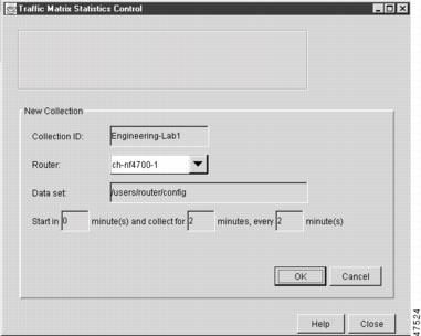
If a valid directory of router configuration files exists on a designated UtilityServer host in the network, the Traffic Matrix Statistics Control window shown in Figure 5 appears.
Step 3 ![]() Specify the new TMS collection parameters, using the Traffic Matrix Statistics Control window.
Specify the new TMS collection parameters, using the Traffic Matrix Statistics Control window.
The window incorporates a New Collection panel that enables you to define a new TMS collection process. To use the NDA for TMS collection, you must specify the following information:
•![]() The name of the collection (Collection ID)—Enter an alphanumeric name of any length without embedded spaces for the TMS collection process on the selected router (see next bullet).
The name of the collection (Collection ID)—Enter an alphanumeric name of any length without embedded spaces for the TMS collection process on the selected router (see next bullet).
•![]() The router from which you want to collect TMS—Use the drop-down box to choose the name of a network device where you want to collect TMS.
The router from which you want to collect TMS—Use the drop-down box to choose the name of a network device where you want to collect TMS.
•![]() How often and how long to collect TMS—Specify each of the following in minutes:
How often and how long to collect TMS—Specify each of the following in minutes:
–![]() How much time is to elapse before the TMS collection process begins ("Start in" field)
How much time is to elapse before the TMS collection process begins ("Start in" field)
–![]() The overall duration of the TMS collection process ("collect for" field)
The overall duration of the TMS collection process ("collect for" field)
–![]() How often "snapshots" of the traffic counters in the selected router are to be exported to the designated TMS data repository ("every" field)
How often "snapshots" of the traffic counters in the selected router are to be exported to the designated TMS data repository ("every" field)
The window for entering this information on the NDA is similar to the one shown in Figure 5.
Figure 5 Setting the NDA Traffic Matrix Statistics Control Window Collection Parameters
Step 4 ![]() Click OK in the New Collection panel.
Click OK in the New Collection panel.
The Traffic Matrix Statistics Control window confirms the information you entered, and the new collection name appears at the top left corner of the window.
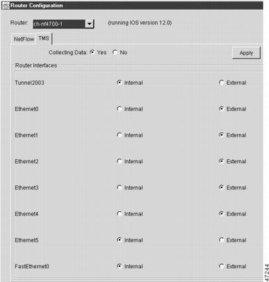
Step 5 ![]() Select the TMS tab in the Router Configuration window in the NDA.
Select the TMS tab in the Router Configuration window in the NDA.
The TMS Router Configuration panel shown in Figure 6 appears. This panel enables you to configure network devices to export TMS data. (For instructions on locating the Router Configuration window, refer to the Network Data Analyzer Installation and User Guide.)
Step 6 ![]() Set internal and external interfaces on the router.
Set internal and external interfaces on the router.
The Router Configuration window allows you to set the interfaces on the backbone router to collect internal and external packet and byte data. By default, all interfaces are set to collect internal data. Single-selection buttons allow you to associate the interface with either internal data or external data. You can select only one radio button for an interface at one time. Set the interface to collect internal or external data by clicking the appropriate radio button.
The window for selecting this information on the NDA is similar to the one shown in Figure 6.
Figure 6 Setting the NDA Configuration Window
Step 7 ![]() Click Apply in the Router Configuration window.
Click Apply in the Router Configuration window.
Any changes that you have made to the configuration parameters in the TMS Router Configuration panel are applied to the currently selected device. The Apply button affects only changes made in the panel where the button is located.
When the NDA asks if you want to enable Cisco Express Forwarding, click Yes.
Interpreting the Statistics in the tmstats_ascii File
This section contains instructions for interpreting the statistics in the tmstats_ascii file. For conceptual information about the tmstats_ascii file, see the "Statistics in the timestats_ascii File" section.
SUMMARY STEPS
1. ![]() more system:/vfiles/tmstats_ascii
more system:/vfiles/tmstats_ascii
2. ![]() Interpret the header and record information in the tmstats_ascii file.
Interpret the header and record information in the tmstats_ascii file.
DETAILED STEPS
Step 1 ![]() more system:/vfiles/tmstats_ascii
more system:/vfiles/tmstats_ascii
Enter this command on the backbone router to view the statistics in the ASCII file. For example:
Router# more system:/vfiles/tmstats_ascii
VERSION 1|ADDR 172.27.32.24|AGGREGATION TrafficMatrix.ascii|SYSUPTIME 41428|routerUTC
3104467160|NTP unsynchronized|DURATION 1|
p|10.1.0.0/16|242|1|50|2|100
p|172.27.32.0/22|242|0|0|0|0
This is an example of a tmstats_ascii file. The example contains a header information and two records. The header information and each record begin on a separate line. A bar (|) separates consecutive fields within a header or record. The first field in a record specifies the type of record.
Step 2 ![]() Interpret the header and record information in the tmstats_ascii file.
Interpret the header and record information in the tmstats_ascii file.
Each tmstats_ascii file displayed consists of header information and records. The file in the example in Step 1 contains header information and two destination prefix records.
Refer to the following sections for a description of header and record information:
•![]() Header information—"tmstats_ascii File Header Description" section
Header information—"tmstats_ascii File Header Description" section
•![]() Destination prefix record (dynamic label switching or traffic engineering (TE) tunnel data)—"Destination Prefix Record Description" section
Destination prefix record (dynamic label switching or traffic engineering (TE) tunnel data)—"Destination Prefix Record Description" section
•![]() Tunnel midpoint record (TE tunnel midpoint data)—"Tunnel Midpoint Record Description" section
Tunnel midpoint record (TE tunnel midpoint data)—"Tunnel Midpoint Record Description" section
Viewing Information in the tmsasinfo File: BGP Neighbor Autonomous Systems for IGP Destinations
Perform the following task to view information in the tmsasinfo file about BGP neighbor autonomous systems (ASs) for IGP destinations.
The TMS feature also displays the BGP neighbor ASs associated with each IGP destination. You can display all the neighbor ASs for any IGP destination. The tmsasinfo file is in ASCII format. It is the only format provided for this data.
For conceptual information about the tmsasinfofile, see the "Statistics in the tmsasinfo File" section.
SUMMARY STEPS
1. ![]() more system:/vfiles/tmsasinfo
more system:/vfiles/tmsasinfo
2. ![]() View the header and record information in the tmsasinfo file.
View the header and record information in the tmsasinfo file.
DETAILED STEPS
Step 1 ![]() more system:/vfiles/tmsasinfo
more system:/vfiles/tmsasinfo
Enter this command on the backbone router to view the statistics in the tmsasinfo ASCII file. For example:
Router# more system:/vfiles/tmsasinfo
VERSION 1|ADDR 10.10.10.10|AGGREGATION ASList.ascii|SYSUPTIME 619855|routerUTC
3334075555|DURATION 0
10.1.1.2/32|65535|192.168.1.0/24
This is an example of a tmsasinfo file. The example contains a header information and one
record. The header information and each record begin on a separate line. A bar (|)
separates consecutive fields within a header or record.
Step 2 ![]() View the header and record information in the tmasinfo file.
View the header and record information in the tmasinfo file.
Refer to the following sections for a description of header and record information:
•![]() Header information—"Header Format for the tmsasinfo File" section.
Header information—"Header Format for the tmsasinfo File" section.
•![]() Neighbor AS Record—"Neighbor AS Record in the tmsasinfo File" section. The file displays BGP ASs associated with each IGP destination.
Neighbor AS Record—"Neighbor AS Record in the tmsasinfo File" section. The file displays BGP ASs associated with each IGP destination.
Verifying Cisco Express Forwarding Network Accounting Information
Perform the following task to verify that Cisco Express Forwarding networking accounting information is as you expected.
SUMMARY STEPS
1. ![]() enable
enable
2. ![]() show ip cef summary
show ip cef summary
3. ![]() show ip cef interface-type slot/subslot/port[.subinterface-number] detail
show ip cef interface-type slot/subslot/port[.subinterface-number] detail
4. ![]() disable
disable
DETAILED STEPS
Step 1 ![]() enable
enable
Use this command to enable privileged EXEC mode. Enter your password if prompted. For example:
Router> enable
Router#
Step 2 ![]() show ip cef summary
show ip cef summary
Use this command to display the collected Cisco Express Forwarding network accounting information. For example:
Router# show ip cef summary
IP CEF with switching (Table Version 19), flags=0x0
19 routes, 0 reresolve, 0 unresolved (0 old, 0 new), peak 1
19 leaves, 17 nodes, 19960 bytes, 58 inserts, 39 invalidations
0 load sharing elements, 0 bytes, 0 references
universal per-destination load sharing algorithm, id E3296D5B
3(1) CEF resets, 0 revisions of existing leaves
Resolution Timer: Exponential (currently 1s, peak 1s)
0 in-place/0 aborted modifications
refcounts: 4628 leaf, 4608 node
Adjacency Table has 7 adjacencies
This command shows sample accounting information on a router with Central Cisco Express Forwarding enabled. In this example, the Cisco Express Forwarding table contains a total or 19 entries, 0 entries need to be reresolved, 0 entries do not have resolved recursions, and the highest number of unresolved entries is 1. The Cisco Express Forwarding Trie contains 19 leaves and 17 nodes, which take up 19960 bytes of memory. The number of routes inserted into the table is 58 and 39 routes have been invalidated. This command shows no load sharing elements. The per-destination load sharing algorithm is configured and the identifier is E3296D5D.
The following command is sample output for a router with distributed Cisco Express Forwarding enabled:
Router# show ip cef summary
IP Distributed CEF with switching (Table Version 36), flags=0x0
16 routes, 0 reresolve, 0 unresolved (0 old, 0 new), peak 1
19 leaves, 17 nodes, 19960 bytes, 39 inserts, 20 invalidations
0 load sharing elements, 0 bytes, 0 references
universal per-destination load sharing algorithm, id E3296D5B
2(0) CEF resets, 0 revisions of existing leaves
Resolution Timer: Exponential (currently 1s, peak 1s)
0 in-place/0 aborted modifications
refcounts: 4628 leaf, 4608 node
Step 3 ![]() show ip cef interface-type slot/subslot/port[.subinterface-number] detail
show ip cef interface-type slot/subslot/port[.subinterface-number] detail
Use this command to show detailed Cisco Express Forwarding network accounting information for a specified interface type and number. The following is sample output from the show ip cef detail command for interface FastEthernet 0/0/0. It shows all the prefixes resolving through adjacency pointing to next hop interface FastEthernet 0/0/0 and next hop interface IP address 172.29.233.33.
For example, for FastEthernet interface 0/0/0, IP address 172.29.233.33:
Router# show ip cef fastethernet 0/0/0 detail
IP Distributed CEF with switching (Table Version 136808)
45800 routes, 8 unresolved routes (0 old, 8 new)
45800 leaves, 2868 nodes, 8444360 bytes,
136808 inserts, 91008 invalidations
1 load sharing elements, 208 bytes, 1 references
1 CEF resets, 1 revisions of existing leaves
refcounts: 527343 leaf, 465638 node
172.29.233.33/32, version 7417, cached adjacency 172.29.233.33
0 packets, 0 bytes,
Adjacency-prefix
via 172.29.233.33, FastEthernet0/0/0, 0 dependencies
next hop 172.29.233.33, FastEthernet0/0/0
valid cached adjacency
0 packets, 0 bytes switched through the prefix
tmstats: external 0 packets, 0 bytes
internal 0 packets, 0 bytes
Step 4 ![]() disable
disable
Use this command to exit to user EXEC mode. For example:
Router# disable
Router>
Configuration Examples for Configuring Cisco Express Forwarding Network Accounting
The following sections contain configuration examples for Cisco Express Forwarding accounting:
•![]() Example: Configuring Cisco Express Forwarding Network Accounting
Example: Configuring Cisco Express Forwarding Network Accounting
•![]() Example: Enabling a Backbone Router to Collect TMS Data
Example: Enabling a Backbone Router to Collect TMS Data
•![]() Example: IP Cisco Express Forwarding Nonrecursive Accounting Configuration
Example: IP Cisco Express Forwarding Nonrecursive Accounting Configuration
•![]() Example: Interpreting the Statistics in the tmstats_ascii File
Example: Interpreting the Statistics in the tmstats_ascii File
Example: Configuring Cisco Express Forwarding Network Accounting
The following example shows how to enable the collection of Cisco Express Forwarding accounting information:
configure terminal
!
ip cef accounting
end
Example: Enabling a Backbone Router to Collect TMS Data
The following example shows how to enable a backbone router to collect TMS data:
configure terminal
!
ip cef
ip cef accounting non-recursive
!
interface fe1/0/0
ip cef accounting non-recursive external
end
For a sample backbone configuration, see the "Example: IP Cisco Express Forwarding Nonrecursive Accounting Configuration" section.
Example: IP Cisco Express Forwarding Nonrecursive Accounting Configuration
The following example shows an IP Cisco Express Forwarding accounting configuration. The example shows how to enable routers to count the number of internal and external packets and bytes that travel through the backbone routers. Figure 7 shows the sample backbone configuration.
Figure 7 Sample Backbone Configuration
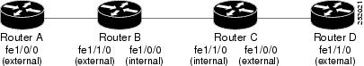
Router A Configuration
Router(config)# ip cef
Router(config)# ip cef accounting non-recursive
Router(config)# interface fe1/0/0
Router(config-if)# ip cef accounting non-recursive external
Router B Configuration: fe1/1/0
Router(config)# ip cef
Router(config)# ip cef accounting non-recursive
Router(config)# interface fe1/1/0
Router(config-if)# ip cef accounting non-recursive external
Router B Configuration: fe1/0/0:
Router(config)# interface fe1/0/0
Router(config-if)# ip cef accounting non-recursive internal
Router C Configuration: fe1/1/0:
Router(config)# ip cef
Router(config)# ip cef accounting non-recursive
Router(config)# interface fe1/1/0
Router(config-if)# ip cef accounting non-recursive internal
Router C Configuration: fe1/0/0:
Router(config)# interface fe1/0/0
Router(config-if)# ip cef accounting non-recursive external
Router D Configuration
Router(config)# ip cef
Router(config)# ip cef accounting non-recursive
Router(config)# interface fe1/1/0
Router(config-if)# ip cef accounting non-recursive external
Example: Interpreting the Statistics in the tmstats_ascii File
The following example shows the contents of tmstats_ascii file:
Router# more system:/vfiles/tmstats_ascii
VERSION 1|ADDR 172.27.32.24|AGGREGATION TrafficMatrix.ascii|SYSUPTIME 41428|routerUTC
3104467160|NTP unsynchronized|DURATION 1|
p|10.1.0.0/16|242|1|50|2|100
p|172.27.32.0/22|242|0|0|0|0
This example contains header information and two destination prefix records. The records represent dynamic label switching or traffic engineering (TE) tunnel data indicated by the initial "p."
Additional References
Related Documents
|
|
|
|---|---|
Cisco IOS commands |
|
List of the features documented in the Cisco Express Forwarding modules |
|
Overview of the Cisco Express Forwarding feature |
|
Tasks for enabling or disabling Cisco Express Forwarding or distributed Cisco Express Forwarding |
|
Tasks for configuring load-balancing schemes for Cisco Express Forwarding |
Configuring a Load-Balancing Scheme for Cisco Express Forwarding Traffic |
Tasks for configuring Cisco Express Forwarding consistency checkers |
Configuring Cisco Express Forwarding Consistency Checkers for Route Processors and Line Cards |
Tasks for configuring epochs for Cisco Express Forwarding tables |
Configuring Epochs to Clear and Rebuild Cisco Express Forwarding and Adjacency Tables |
Commands for configuring and managing Cisco Express Forwarding |
|
Tasks for customizing the display of Cisco Express Forwarding event trace messages |
Customizing the Display of Cisco Express Forwarding Event Trace Messages |
Standards
|
|
|
|---|---|
No new or modified standards are supported by this feature, and support for existing standards has not been modified by this feature. |
— |
MIBs
RFCs
|
|
|
|---|---|
No new or modified RFCs are supported by this feature, and support for existing RFCs has not been modified by this feature. |
— |
Technical Assistance
Feature Information for Configuring Cisco Express Forwarding Network Accounting
Table 6 lists the features in this module.
Use Cisco Feature Navigator to find information about platform support and software image support. Cisco Feature Navigator enables you to determine which Cisco IOS XE software images support a specific software release, feature set, or platform. To access Cisco Feature Navigator, go to http://www.cisco.com/go/cfn. An account on Cisco.com is not required.
Note ![]() Table 6 lists only the Cisco IOS XE software release that introduced support for a given feature in a given Cisco IOS XE software release train. Unless noted otherwise, subsequent releases of that Cisco IOS XE software release train also support that feature.
Table 6 lists only the Cisco IOS XE software release that introduced support for a given feature in a given Cisco IOS XE software release train. Unless noted otherwise, subsequent releases of that Cisco IOS XE software release train also support that feature.
Glossary
AS—autonomous system. A collection of networks under a common administration sharing a common routing strategy. Autonomous systems are subdivided by areas. An autonomous system must be assigned a unique 16-bit number by the Internet Assigned Numbers Authority (IANA).
adjacency—A relationship formed between selected neighboring routers and end nodes for the purpose of exchanging routing information. Adjacency is based upon the use of a common media segment by the routers and nodes involved.
BGP—Border Gateway Protocol. An interdomain routing protocol that replaces Exterior Gateway Protocol (EGP). BGP exchanges reachability information with other BGP systems. It is defined by RFC 1163.
Cisco Express Forwarding—A Layer 3 switching technology. Cisco Express Forwarding can also refer to central Cisco Express Forwarding mode, one of two modes of Cisco Express Forwarding operation. Cisco Express Forwarding enables a Route Processor to perform express forwarding. Distributed Cisco Express Forwarding is the other mode of Cisco Express Forwarding operation.
distributed Cisco Express Forwarding—A type of Cisco Express Forwarding switching in which line cards maintain identical copies of the Forwarding Information Base (FIB) and adjacency tables. The line cards perform the express forwarding between port adapters; this relieves the Route Processor of involvement in the switching operation.
FIB—forwarding information base. A component of Cisco Express Forwarding. The router uses the FIB lookup table to make destination-based switching decisions during Cisco Express Forwarding operation. The router maintains a mirror image of the forwarding information in an IP routing table.
IGP— Interior Gateway Protocol. An internet protocol used to exchange routing information within an autonomous system. Examples of common Internet IGPs include Interior Gateway Routing Protocol (IGRP), Open Shortest Path First (OSPF), and Routing Information Protocol (RIP).
label—A short fixed-length data construct that tells switching nodes how to forward data (packets or cells).
line card—A general term for an interface processor that can be used in various Cisco products.
prefix—The network address portion of an IP address. A prefix is specified by a network and mask and is generally represented in the format network/mask. The mask indicates which bits are the network bits. For example, 1.0.0.0/16 means that the first 16 bits of the IP address are masked, making them the network bits. The remaining bits are the host bits. In this example, the network number is 10.0.
RP—Route Processor. The processor module in the routers that contains the CPU, system software, and most of the memory components that are used in the router. It is sometimes called a supervisory processor.
TE—traffic engineering. Techniques and processes that cause routed traffic to travel through the network on a path other than the one that would have been chosen if standard routing methods were used.
traffic engineering tunnel—A label-switched tunnel that is used for traffic engineering. Such a tunnel is set up through means other than normal Layer 3 routing; it is used to direct traffic over a path different from the one that Layer 3 routing could cause the tunnel to take.
TMS—Traffic Matrix Statistics. An IOS feature that enables an administrator to capture and analyze traffic data entering a backbone that is running the Border Gateway Protocol (BGP). This feature also allows an administrator to determine the neighbor autonomous systems of a BGP destination
VPN—Virtual Private Network. The result of a router configuration that enables IP traffic to use tunneling to travel securely over a public TCP/IP network.
VRF—A Virtual Private Network (VPN) routing/forwarding instance. A VRF consists of an IP routing table, a derived forwarding table, a set of interfaces that use the forwarding table, and a set of rules and routing protocols that determine what goes into the forwarding table. In general, a VRF includes the routing information that defines a customer VPN site that is attached to a PE router.
 Feedback