-
- Managing Configuration Files
- Exclusive Configuration Change Access (Configuration Lock) and Access Session Locking
- Configuration Generation Performance Enhancement
- Configuration Replace and Configuration Rollback
- Contextual Configuration Diff Utility
- Configuration Change Notification and Logging
- Configuration Partitioning
Cisco IOS XE Configuration Fundamentals Configuration Guide, Release 2
Bias-Free Language
The documentation set for this product strives to use bias-free language. For the purposes of this documentation set, bias-free is defined as language that does not imply discrimination based on age, disability, gender, racial identity, ethnic identity, sexual orientation, socioeconomic status, and intersectionality. Exceptions may be present in the documentation due to language that is hardcoded in the user interfaces of the product software, language used based on RFP documentation, or language that is used by a referenced third-party product. Learn more about how Cisco is using Inclusive Language.
- Updated:
- January 22, 2009
Chapter: Using AutoInstall to Remotely Configure Cisco Networking Devices
- Finding Feature Information
- Contents
- Information About Using AutoInstall to Remotely Configure Cisco Networking Devices
- AutoInstall
- Services and Servers Used By AutoInstall: Dynamic Assignment of IP Addresses
- Services and Servers Used By AutoInstall: IP-to-Hostname Mapping
- Services and Servers Used By AutoInstall: Storage and Transmission of Configuration Files
- Networking Devices Used by AutoInstall
- Configuration Files Used by AutoInstall
- Configuration Options for AutoInstall
- The AutoInstall Process
- Benefits of Using AutoInstall to Remotely Configure a Cisco Networking Device
- AutoInstall
- Using AutoInstall to Set Up Devices Connected to LANs: Example
- Determining the Value for the DHCP Client Identifier Manually
- Determining the Value for the DHCP Client Identifier Automatically
- Creating a Private DHCP Pool for Each of The Routers
- Creating Configuration Files for Each Router
- Creating the network-confg file
- Setting Up the Routers with AutoInstall
- Saving the Configuration Files on The Routers
- Removing the Private DHCP Address Pools from R1
- Using AutoInstall to Set Up Devices Connected to WANs: Example
Using AutoInstall to Remotely Configure Cisco Networking Devices
AutoInstall enables remote, automatic configuration of networking devices. AutoInstall is typically used to set up new networking devices remotely. You can, however, use AutoInstall to configure existing networking devices after you remove the configuration file from their NVRAM. The AutoInstall process uses pre-existing configuration files that are stored on a TFTP server.
In this module the term networking device means a router that runs Cisco IOS XE software. Also, the following terms are used interchangeably:
•![]() initial configuration and startup configuration
initial configuration and startup configuration
•![]() set up and configure
set up and configure
Finding Feature Information
For the latest feature information and caveats, see the release notes for your platform and software release. To find information about the features documented in this module, and to see a list of the releases in which each feature is supported, see the"Feature Information for Using AutoInstall to Remotely Configure a Cisco Networking Device" section.
Use Cisco Feature Navigator to find information about platform support and Cisco IOS XE software image support. To access Cisco Feature Navigator, go to http://www.cisco.com/go/cfn. An account on Cisco.com is not required.
Contents
•![]() Information About Using AutoInstall to Remotely Configure Cisco Networking Devices
Information About Using AutoInstall to Remotely Configure Cisco Networking Devices
•![]() How to Use AutoInstall to Remotely Configure Cisco Networking Devices
How to Use AutoInstall to Remotely Configure Cisco Networking Devices
•![]() Configuration Examples for Using AutoInstall to Remotely Configure Cisco Networking Devices
Configuration Examples for Using AutoInstall to Remotely Configure Cisco Networking Devices
•![]() Feature Information for Using AutoInstall to Remotely Configure a Cisco Networking Device
Feature Information for Using AutoInstall to Remotely Configure a Cisco Networking Device
Information About Using AutoInstall to Remotely Configure Cisco Networking Devices
Before you configure or use AutoInstall, you should understand the following information:
•![]() Benefits of Using AutoInstall to Remotely Configure a Cisco Networking Device
Benefits of Using AutoInstall to Remotely Configure a Cisco Networking Device
AutoInstall
AutoInstall can be used to load a final full configuration, or a partial temporary configuration, on to a networking device that is being configured with AutoInstall.

Tip ![]() When you use AutoInstall to load a partial temporary configuration, you must finish configuring the device manually.
When you use AutoInstall to load a partial temporary configuration, you must finish configuring the device manually.
The requirements for provisioning your network for AutoInstall, and the configuration options for provisioning AutoInstall are explained in these sections:
•![]() Services and Servers Used By AutoInstall: Dynamic Assignment of IP Addresses
Services and Servers Used By AutoInstall: Dynamic Assignment of IP Addresses
•![]() Services and Servers Used By AutoInstall: IP-to-Hostname Mapping
Services and Servers Used By AutoInstall: IP-to-Hostname Mapping
•![]() Services and Servers Used By AutoInstall: Storage and Transmission of Configuration Files
Services and Servers Used By AutoInstall: Storage and Transmission of Configuration Files
•![]() Networking Devices Used by AutoInstall
Networking Devices Used by AutoInstall
•![]() Configuration Files Used by AutoInstall
Configuration Files Used by AutoInstall
•![]() Configuration Options for AutoInstall
Configuration Options for AutoInstall
Services and Servers Used By AutoInstall: Dynamic Assignment of IP Addresses
The network must be able to provide the dynamic assignment of an IP address to the networking device that is being configured with AutoInstall. The type of IP address assignment server that is used depends on the type of connection that the networking that is being configured with AutoInstall has to the network.
AutoInstall uses these types of IP address servers:
DHCP Servers
Networking devices using AutoInstall over a LAN connection require a DHCP server to provide an IP address dynamically. This requirement applies to Fast Ethernet, Token Ring, and FDDI interfaces. The network must be configured to provide IP connectivity between the DHCP server and any devices that are using AutoInstall over LAN connections.
DHCP (defined in RFC 2131) is an extension of the functionality provided by the Bootstrap Protocol (defined in RFC 951). DHCP provides the framework for passing configuration information to hosts on a TCP/IP network. DHCP adds the capability of automatic allocation of reusable network addresses and additional configuration options such as a router (gateway) IP address, a TFTP server IP address, the name of a boot file to load, and the domain name to use. DHCP servers can be configured on routers, UNIX servers, Microsoft Windows-based servers, and other platforms.
DHCP servers typically assign IP addresses from a pool of IP addresses randomly. It is possible for a device that uses DHCP to obtain its IP address to have a different IP address every time it is connected to the network. This creates a problem for the AutoInstall process when you want to ensure that a particular device is assigned a specific hostname during the AutoInstall process. For example, if you are installing routers on different floors in a remote site and each router is supposed to be assigned a name that indicates its location, such as ChicagoHQ-1st and ChicagoHQ-2nd, you need to ensure that each device gets the IP address that will be mapped to its correct hostname.
The process of ensuring that a device is assigned a specific IP address is referred to as creating a reservation. A reservation is a manually configured relationship between an IP address and a physical layer address of a LAN interface on the device. Many Cisco IOS XE-based devices do not use their MAC address when they request an IP address via DHCP. They use a much longer client identifier instead. Due to the complexity of identifying the client identifier so that you can preconfigure a reservation, and the complexity of finding out if the new device uses its MAC address or the client identifier, we recommend that you allow a new device to obtain an IP address without using a DHCP reservation first in order to discover if the device is using its MAC address or a client identifier. When you have learned how the new device is identifying itself to the DHCP server, you can make a note of the format and create a reservation for it. The next time the new device is rebooted it should obtain the IP address that you reserved to ensure that the new device is assigned the correct hostname. Refer to the information on creating DHCP reservations that was provided with your DHCP server software. The process for creating reservations using Cisco IOS XE based DHCP servers is explained in the "Using AutoInstall to Set Up Devices Connected to LANs: Example" section. This section includes instructions for identifying the client identifier before the device is connected to the network so that you can preconfigure the DHCP reservations.

Note ![]() This document uses a Cisco router as the DHCP server for using AutoInstall to configure LAN-connected networking devices. If you are using a different device as your DHCP server ensure that you have the user documentation for it available in the event that you need help configuring it.
This document uses a Cisco router as the DHCP server for using AutoInstall to configure LAN-connected networking devices. If you are using a different device as your DHCP server ensure that you have the user documentation for it available in the event that you need help configuring it.
Note ![]() There are several configuration parameters such as TFTP server addresses, DNS server addresses, domain names and so on, that can be provided to LAN-connected clients by DHCP servers during the process of assigning IP addresses to clients. These parameters are not required by AutoInstall, therefore they are not included in this document. If you know how to use these parameters you can include them in your DHCP server configuration when you are using AutoInstall to setup your networking devices.
There are several configuration parameters such as TFTP server addresses, DNS server addresses, domain names and so on, that can be provided to LAN-connected clients by DHCP servers during the process of assigning IP addresses to clients. These parameters are not required by AutoInstall, therefore they are not included in this document. If you know how to use these parameters you can include them in your DHCP server configuration when you are using AutoInstall to setup your networking devices.
For more information on DHCP services visit the IETF RFC site (http://www.ietf.org/rfc.html) and look for RFCs about DHCP. Most server operating systems support DHCP servers. Refer to the documentation that was provided with your operating system for more information.
SLARP Servers
A router that is being configured with AutoInstall over a serial interface using HDLC encapsulation will send a Serial Line ARP (SLARP) request for an IP address over the serial interface that is connected to the staging router.
The serial interface of the staging router must be configured with an IP address in which the host portion is 1 or 2, such as 192.168.10.1 or 192.168.10.2. The staging router will send a SLARP response to the router that is being configured with AutoInstall that contains the value that the staging router is not using. For example, if the interface on the staging router that is connected to the router that is being configured with AutoInstall is using 192.168.10.1 as its IP address, the staging router will send a SLARP response with a value of 192.168.10.2 to the router that is being configured with AutoInstall.
Tip ![]() If you are using a mask of 255.255.255.252 on the serial interface of the staging router SLARP will assign the available IP host address to the new device. For example, if you assign IP address 198.162.10.5 255.255.255.252 to serial 0 on the staging router, SLARP will assign 198.162.10.6 to the new device. If you assign IP addresses 198.162.10.6 255.255.255.252 to serial 0 on the staging router SLARP will assign 198.162.10.5 to the new device.
If you are using a mask of 255.255.255.252 on the serial interface of the staging router SLARP will assign the available IP host address to the new device. For example, if you assign IP address 198.162.10.5 255.255.255.252 to serial 0 on the staging router, SLARP will assign 198.162.10.6 to the new device. If you assign IP addresses 198.162.10.6 255.255.255.252 to serial 0 on the staging router SLARP will assign 198.162.10.5 to the new device.
Figure 2 shows an example of SLARP.
In Figure 1, the IP address of serial interface 0 on the staging router (R2) is 192.168.10.1. SLARP therefore assigns the IP address 192.168.10.2 to serial interface 0 on the new device.
Figure 1 Using SLARP to Assign an IP Address to a New Device
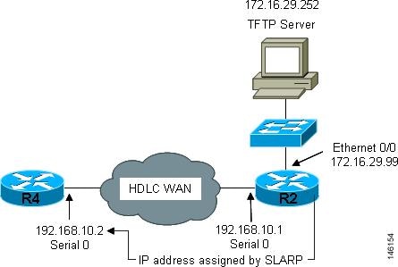
Note ![]() AutoInstall over a serial interface using HDLC can be performed only over the first serial port on a new device (serial interface 0 or serial interface x/0). The staging router and new device must be directly connected using the first serial interface port on the new device; for example, serial 0/0 or if the first serial port is in the second slot of the device, serial 2/0.
AutoInstall over a serial interface using HDLC can be performed only over the first serial port on a new device (serial interface 0 or serial interface x/0). The staging router and new device must be directly connected using the first serial interface port on the new device; for example, serial 0/0 or if the first serial port is in the second slot of the device, serial 2/0.
Tip ![]() The IP address that is assigned to the router that is being configured with AutoInstall by SLARP from the staging router is the IP address that you must use in the ip host hostname ip-address command in the AutoInstall network-confg or cisconet.cfg file to ensure that the router that is being configured with AutoInstall is assigned the correct hostname so that it can request its host-specific configuration file.
The IP address that is assigned to the router that is being configured with AutoInstall by SLARP from the staging router is the IP address that you must use in the ip host hostname ip-address command in the AutoInstall network-confg or cisconet.cfg file to ensure that the router that is being configured with AutoInstall is assigned the correct hostname so that it can request its host-specific configuration file.
BOOTP Servers
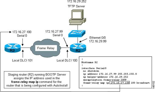
A router that is being configured with AutoInstall over a serial interface using Frame Relay encapsulation will send a BOOTP request for an IP address over the serial interface that is connected to the staging router.
The staging router learns the correct IP address to provide in its BOOTP response to the router that is being configured with AutoInstall by examining the frame-relay map ip ip-address dlci command that is configured on the interface that it is using to connect to the router that is being configured with AutoInstall.
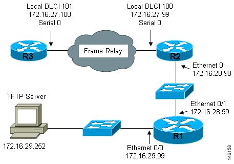
In Figure 2 R2 is the staging router. R2 has the frame-relay map ip 172.16.27.100 100 broadcast command configured on interface serial 0. When R2 receives the BOOTP request for an IP address from R3 during the AutoInstall process, R3 will reply with 172.16.27.100.
Figure 2 Example of Using BOOTP for Autoinstall Over a Frame Relay Network
Tip ![]() The limitation imposed by SLARP in which the IP addresses for the new device and the staging router must end in either .1 or .2 does not apply to BOOTP. BOOTP for AutoInstall over Frame Relay supports all host addresses for the IP address subnet that is assigned to the Frame Relay circuit between the router that is being configured with AutoInstall and the staging router.
The limitation imposed by SLARP in which the IP addresses for the new device and the staging router must end in either .1 or .2 does not apply to BOOTP. BOOTP for AutoInstall over Frame Relay supports all host addresses for the IP address subnet that is assigned to the Frame Relay circuit between the router that is being configured with AutoInstall and the staging router.
Tip ![]() The IP address that is assigned to the router that is being configured with AutoInstall by BOOTP from the staging router is the IP address that you must use in the ip host hostname ip-address command in the AutoInstall network-confg or cisconet.cfg file to ensure that the router that is being configured with AutoInstall is assigned the correct hostname so that it can request its host-specific configuration file.
The IP address that is assigned to the router that is being configured with AutoInstall by BOOTP from the staging router is the IP address that you must use in the ip host hostname ip-address command in the AutoInstall network-confg or cisconet.cfg file to ensure that the router that is being configured with AutoInstall is assigned the correct hostname so that it can request its host-specific configuration file.
Note ![]() AutoInstall over a serial interface using Frame Relay encapsulation can be performed only over the first serial port on a new device (serial interface 0 or serial interface x/0). The staging router and new device must be directly connected using the first serial interface port on the new device; for example, serial 0/0 or if the first serial port is in the second slot of the device, serial 2/0.
AutoInstall over a serial interface using Frame Relay encapsulation can be performed only over the first serial port on a new device (serial interface 0 or serial interface x/0). The staging router and new device must be directly connected using the first serial interface port on the new device; for example, serial 0/0 or if the first serial port is in the second slot of the device, serial 2/0.
Services and Servers Used By AutoInstall: IP-to-Hostname Mapping
If you want the networking device to load a full configuration file during the AutoInstall process, the networking device must be able to determine its hostname so that it can request the configuration file that you created specifically for it.
The following caveats apply to the provisioning of IP address to hostname mapping for AutoInstall:
•![]() Any networking device that is being configured with AutoInstall can determine its hostname by loading one of the AutoInstall network configuration files (network-confg or cisconet.cfg) from the TFTP server that contain the ip host hostname ip-address commands. For example, to map host R3 to IP address 198.162.100.3, the network-confg or cisconet.cfg file must contain the ip host r3 198.162.100.3 command.
Any networking device that is being configured with AutoInstall can determine its hostname by loading one of the AutoInstall network configuration files (network-confg or cisconet.cfg) from the TFTP server that contain the ip host hostname ip-address commands. For example, to map host R3 to IP address 198.162.100.3, the network-confg or cisconet.cfg file must contain the ip host r3 198.162.100.3 command.
•![]() A networking device that is being configured with AutoInstall over a LAN interface can also determine its hostname by querying a DNS server. If the DNS server is not connected to the same LAN the device must learn the IP address of the DNS server from the DHCP server during the process of obtaining its dynamically assigned IP address from the DHCP server.
A networking device that is being configured with AutoInstall over a LAN interface can also determine its hostname by querying a DNS server. If the DNS server is not connected to the same LAN the device must learn the IP address of the DNS server from the DHCP server during the process of obtaining its dynamically assigned IP address from the DHCP server.
DNS Servers
DNS servers are used to provide a network service that maps hostnames to IP addresses and IP addresses to hostnames (reverse DNS lookups). Anytime that you use a hostname to initiate an IP connection to a host, your PC must determine the IP address that is assigned to the hostname that you want to contact. For example, when you visit Cisco's website (http://www.cisco.com/) your PC sends a DNS query to a DNS server to discover the current IP address that can be used to contact Cisco's website.
For more information on DNS services visit the IETF RFC site (http://www.ietf.org/rfc.html) and look for RFCs about DNS. The Name Server LookUp tool (nslookup) is very useful for learning more about DNS. There are several excellent websites available about nslookup that you can find by searching for them.
Services and Servers Used By AutoInstall: Storage and Transmission of Configuration Files
TFTP is a protocol used to transfer files between devices on a network. A TFTP server is a device that uses TFTP to transfer files to devices. TFTP servers can be configured on UNIX servers, Microsoft Windows-based PCs and servers, and other platforms.
Tip ![]() If you do not have a TFTP server available you can configure a Cisco IOS XE-based router as a TFTP server using the tftp-server file-system:filename command. Refer to the Configuring Basic File Transfer Services guide http://www.cisco.com/univercd/cc/td/doc/product/software/ios122/122cgcr/ffun_c/ffcprt2/fcf011.htm for more information on configuring your router as a TFTP server.
If you do not have a TFTP server available you can configure a Cisco IOS XE-based router as a TFTP server using the tftp-server file-system:filename command. Refer to the Configuring Basic File Transfer Services guide http://www.cisco.com/univercd/cc/td/doc/product/software/ios122/122cgcr/ffun_c/ffcprt2/fcf011.htm for more information on configuring your router as a TFTP server.
Cisco routers use TFTP to load the configuration files that are required for AutoInstall. You must have a TFTP server deployed in your network to provide file storage and file transmission services to the devices that will be using AutoInstall.
For more information on TFTP services visit the IETF RFC site (http://www.ietf.org/rfc.html) and look for RFCs about TFTP. There are several excellent websites available about TFTP that you can find by searching for them. Several freeware and shareware versions of TFTP servers for various operating systems and hardware platforms are available from the Internet.
The following caveats apply to the provisioning of TFTP servers for AutoInstall:
•![]() Devices using AutoInstall over a LAN—If the TFTP server and the devices using AutoInstall are on different LAN segments, you must either configure the ip helper-address address command on all of the interfaces that will receive TFTP session initialization requests from the devices that are using AutoInstall.
Devices using AutoInstall over a LAN—If the TFTP server and the devices using AutoInstall are on different LAN segments, you must either configure the ip helper-address address command on all of the interfaces that will receive TFTP session initialization requests from the devices that are using AutoInstall.
•![]() Devices using AutoInstall over a WAN—If the devices using AutoInstall are connected to a WAN, you must configure the ip helper-address address command on all of the interfaces that will receive TFTP session initialization requests from devices that are using AutoInstall.
Devices using AutoInstall over a WAN—If the devices using AutoInstall are connected to a WAN, you must configure the ip helper-address address command on all of the interfaces that will receive TFTP session initialization requests from devices that are using AutoInstall.
ip helper-address
If the new device does not learn the IP address of the TFTP server via DHCP option 150, it will transmit the TFTP session initialization requests as network layer broadcasts using the IP destination broadcast address of 255.255.255.255. Routers block network layer broadcast datagrams which prevents the TFTP session initialization requests from reaching the TFTP server, and AutoInstall will fail. The solution to this problem is to use the ip helper-address address command. The ip helper-address address command changes the broadcast address of TFTP session initialization request from 255.255.255.255 to the address that is configured with the address argument. For example, the ip helper-address 172.16.29.252 command will change IP destination broadcast address of 255.255.255.255 to 172.16.29.252.
Networking Devices Used by AutoInstall
These networking devices are used by AutoInstall:
•![]() Device That Is Being Configured with AutoInstall
Device That Is Being Configured with AutoInstall
•![]() Intermediate Frame Relay-ATM Switching Device (Optional), page 9
Intermediate Frame Relay-ATM Switching Device (Optional), page 9
Device That Is Being Configured with AutoInstall
A device that is being configured with AutoInstall can be any Cisco IOS XE-based router that supports AutoInstall and does not have a configuration file in its NVRAM.
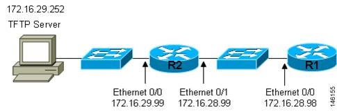
Staging Router
A staging router acts as an intermediary between the TFTP server (to which it must have IP connectivity) and a device that is being configured with AutoInstall when the new device and the TFTP server are connected to different networks. In Figure 3 R1 requires a staging router because it is connected to a different LAN segment than the TFTP server.
Staging routers are required in the following situations:
•![]() Devices using AutoInstall over a LAN—If the TFTP and/or DHCP servers and the devices using AutoInstall are on different LAN segments you must use a staging router.
Devices using AutoInstall over a LAN—If the TFTP and/or DHCP servers and the devices using AutoInstall are on different LAN segments you must use a staging router.
•![]() Devices using AutoInstall over a WAN—If the devices using AutoInstall are connected to a WAN, you must configure the ip helper-address address command on all of the directly connected interfaces that will receive TFTP session initialization requests from the devices that are using AutoInstall.
Devices using AutoInstall over a WAN—If the devices using AutoInstall are connected to a WAN, you must configure the ip helper-address address command on all of the directly connected interfaces that will receive TFTP session initialization requests from the devices that are using AutoInstall.
Figure 3 Example of AutoInstall That Requires a Staging Router
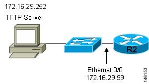
Staging routers are not required when the new device that is being configured with AutoInstall is connected to the same LAN segment as the TFTP and DHCP servers. In Figure 4 R2 does not require a staging server to use AutoInstall because it is on the same LAN segment as the TFTP server.
Figure 4 Example of AutoInstall That Does Not Require a Staging Router
Configuration Files Used by AutoInstall
A configuration file executes predefined commands and settings that enable a device to function in a network. The type of configuration file you choose determines many aspects of how you set up the network for AutoInstall.
These types of files are used by AutoInstall:
•![]() Host-Specific Configuration File
Host-Specific Configuration File
•![]() Default Configuration File (Optional)
Default Configuration File (Optional)
Network Configuration File
This is the first file that the AutoInstall process attempts to use. After the device has obtained an IP address it will try to discover its hostname by attempting to download a network configuration file that contains IP address to host name mappings.
If you want the device to learn its hostname from the network-confg file so that it can download a host-specific configuration file, you must add an entry for the device in the network-confg network configuration file. The syntax for the entry is ip host hostname ip-address where hostname is the name that you want the host to use and ip-address is the address that the host will receive from the IP address server. For example, if you want the new device to use the name Australia, and the IP address that was dynamically assigned the new device is 172.16.29.103, you need to create an entry in the network configuration file that contains the ip host australia 172.16.29.103 command.
The file names used for the network configuration file are network-confg or cisconet.cfg. Routers running AutoInstall will try to load the network-confg from the TFTP server first. If the network-confg is not found on the TFTP server, the AutoInstall process will attempt to load the cisconet.cfg file. The cisconet.cfg filename was used by DOS-based TFTP servers that only supported the old 8.3 file naming convention. We recommend that you use the network-confg filename to avoid the delay that is created when AutoInstall has to timeout attempting to load the network-confg before it attempts to load the cisconet.cfg file.
If you using autoinstall to setup multiple devices you can create one network configuration file that contains an entry for each of the devices.
Host-Specific Configuration File
Host-specific configuration files are a full configuration for each new device. If you decide to use host-specific files, you must create a separate file for each new device that you are using AutoInstall to setup.
The filenames used for the host-specific configuration files are name-confg or name.cfg where the word name is replaced by the hostname of the router. For example, the filename for a router named hqrouter is hqrouter-confg or hqrouter.cfg.
Routers running AutoInstall will try to load the host-specific configuration filename using the format name-confg from the TFTP server first. If the name-confg file is not found on the TFTP server, the AutoInstall process will attempt to load the name.cfg file. The name.cfg file name format was used by DOS based TFTP servers that only supported the old 8.3 file naming convention. We recommend that you use the name-confg filename to avoid the delay that is created when AutoInstall has to timeout attempting to load the name-confg before it attempts to load the name.cfg file.
Tip ![]() If you use the name.cfg format for host-specific configuration files the filenames for hostnames that are longer than 8 characters must be truncated to the first eight characters. For example, the filename for a device with the hostname australia must be truncated to australi.cfg. When AutoInstall maps the IP address assigned to the new router to its hostname of australia in the network configuration file, AutoInstall will attempt to download a host-specific file with the name australi.cfg after it fails to load the host-specific filename austrailia-confg.
If you use the name.cfg format for host-specific configuration files the filenames for hostnames that are longer than 8 characters must be truncated to the first eight characters. For example, the filename for a device with the hostname australia must be truncated to australi.cfg. When AutoInstall maps the IP address assigned to the new router to its hostname of australia in the network configuration file, AutoInstall will attempt to download a host-specific file with the name australi.cfg after it fails to load the host-specific filename austrailia-confg.
Tip ![]() Cisco recommends that you use the host-specific file option for setting up new devices to ensure that each new device is set up properly.
Cisco recommends that you use the host-specific file option for setting up new devices to ensure that each new device is set up properly.
Default Configuration File (Optional)
A default configuration file, which includes minimum configuration information allows you to telnet to the new device and configure it manually.
Tip ![]() If the new device has learned its hostname after it loaded the network configuration file the default configuration file is not used. You must use the host-specific file instead to configure features such as passwords for remote CLI sessions.
If the new device has learned its hostname after it loaded the network configuration file the default configuration file is not used. You must use the host-specific file instead to configure features such as passwords for remote CLI sessions.
Figure 5 is an example of using the default configuration file to stage new routers for remote manual configuration. Routers A, B, and C are new routers that will be added to the network one at a time. You connect the first router and wait for it to load the default configuration file. The default configuration file must have enough information in it to allow the new router to communicate with the PC that you will be using to finish its configuration using a Telnet session. After the default configuration file is loaded on the new router, you can use Telnet to connect to the router to complete its configuration. You must assign a new, unique IP address to its interfaces so that the default configuration file can be used for configuring the next router.

Figure 5 Example of Using the Default Configuration File To Stage Routers For Remote Manual Configuration
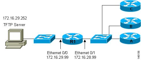
Tip ![]() You must include the commands for configuring passwords for remote Telnet access and access to privileged EXEC mode if you are going to access the routers remotely to complete their configurations save their configuration files to NVRAM.
You must include the commands for configuring passwords for remote Telnet access and access to privileged EXEC mode if you are going to access the routers remotely to complete their configurations save their configuration files to NVRAM.
The filenames used for the default network configuration file are router-confg or router.cfg. Routers running AutoInstall will try to load the router-confg from the TFTP server first. If the router-confg is not found on the TFTP server the AutoInstall process will attempt to load the router.cfg file. The router.cfg file name was used by DOS-based TFTP servers that only supported the old 8.3 file naming convention. We recommend that you use the router-confg filename to avoid the delay that is created when AutoInstall has to timeout while attempting to load the router-confg before it attempts to load the router.cfg file.
If you are using AutoInstall to configure LAN-attached devices, you can specify a different default boot filename in DHCP Option 067.
Configuration Options for AutoInstall
You can provision your network to support AutoInstall using several different combinations of devices and services. For example:
•![]() You can provision all of the services required for AutoInstall (except dynamic IP address assignment using SLARP or BOOTP that must be preformed by a Cisco router) on one network server, or you can provision each service on a different network server.
You can provision all of the services required for AutoInstall (except dynamic IP address assignment using SLARP or BOOTP that must be preformed by a Cisco router) on one network server, or you can provision each service on a different network server.
•![]() You can provision the DHCP service on a Cisco router.
You can provision the DHCP service on a Cisco router.
•![]() The device using AutoInstall can determine its IP address from a DNS server, or you can use one of the AutoInstall network configuration files (network-confg or cisconet.cfg) that contain the ip host hostname ip-address commands.
The device using AutoInstall can determine its IP address from a DNS server, or you can use one of the AutoInstall network configuration files (network-confg or cisconet.cfg) that contain the ip host hostname ip-address commands.
•![]() You can use provision AutoInstall to load a full configuration or a partial configuration onto a device that is using AutoInstall.
You can use provision AutoInstall to load a full configuration or a partial configuration onto a device that is using AutoInstall.
This module focuses on some of the most common methods for provisioning AutoInstall. Refer to the "How to Use AutoInstall to Remotely Configure Cisco Networking Devices" section for information on the most common methods for provisioning AutoInstall.
The AutoInstall Process
The AutoInstall process begins when a networking device that does not have any files in its NVRAM is connected to the network.

Timesaver ![]() You can decrease the time that the AutoInstall process takes to complete by only connecting the interface on the networking device that you want to use for AutoInstall until the AutoInstall process has finished. For example, if you want the networking device to perform AutoInstall over a WAN interface and you connect its LAN interfaces and its WAN interfaces the networking device will attempt to perform AutoInstall over the LAN interfaces before it attempts to use the WAN interfaces. Leaving the LAN interfaces disconnected until the AutoInstall process is finished causes the networking device to initiate the AutoInstall process over its WAN interface immediately.
You can decrease the time that the AutoInstall process takes to complete by only connecting the interface on the networking device that you want to use for AutoInstall until the AutoInstall process has finished. For example, if you want the networking device to perform AutoInstall over a WAN interface and you connect its LAN interfaces and its WAN interfaces the networking device will attempt to perform AutoInstall over the LAN interfaces before it attempts to use the WAN interfaces. Leaving the LAN interfaces disconnected until the AutoInstall process is finished causes the networking device to initiate the AutoInstall process over its WAN interface immediately.
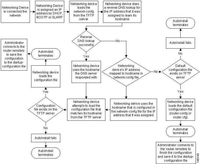
Figure 6 shows the basic flow of the AutoInstall process.
Figure 6 AutoInstall Process Flowchart
Benefits of Using AutoInstall to Remotely Configure a Cisco Networking Device
AutoInstall facilitates the deployment of Cisco routers by allowing you to manage the setup procedure for routers from a central location. The person responsible for physically installing the router does not require specific networking skills. The ability to physically install the router, connect the power and networking cables, and power it on are the only skills required by the installer. The configuration files are stored and managed on a central TFTP server. By using AutoInstall one skilled network technician based at a central site can manage the deployment of several routers in a short period of time.
Two enhancements to AutoInstall:
•![]() AutoInstall Using DHCP for LAN Interfaces
AutoInstall Using DHCP for LAN Interfaces
•![]() How to Use AutoInstall to Remotely Configure Cisco Networking Devices
How to Use AutoInstall to Remotely Configure Cisco Networking Devices
AutoInstall Using DHCP for LAN Interfaces
The AutoInstall Using DHCP for LAN Interfaces feature enhances the benefits of AutoInstall by replacing the use of the Bootstrap Protocol (BOOTP) with the use of the Dynamic Host Configuration Protocol (DHCP) for Cisco IOS AutoInstall over LAN interfaces (specifically Fast Ethernet, Token Ring, and FDDI interfaces).
DHCP (defined in RFC 2131) is an extension of the functionality provided by the BOOTP (defined in RFC 951). DHCP provides the framework for passing configuration information to hosts on a TCP/IP network. DHCP adds the capability of automatic allocation of reusable network addresses and additional configuration options. The IP address procurement phase of the AutoInstall process is accomplished using DHCP for Fast Ethernet, Token Ring, and FDDI interfaces. Uploading of configuration files using unicast TFTP is also allowed.
How to Use AutoInstall to Remotely Configure Cisco Networking Devices
This section describes the how to prepare a router for AutoInstall. Additional examples for using AutoInstall for new routers connected to LANs, HDLC WANs, and Frame Relay networks, are provided in the "Configuration Examples for Using AutoInstall to Remotely Configure Cisco Networking Devices" section.
In most cases you need to configure a staging router through which a new device running AutoInstall sends TFTP, BOOTP, and DNS requests.
Tip ![]() In all cases, you must verify and save the configuration on the networking device after the AutoInstall process is complete. If you do not save the configuration, you must repeat the entire process.
In all cases, you must verify and save the configuration on the networking device after the AutoInstall process is complete. If you do not save the configuration, you must repeat the entire process.
•![]() Disabling the SDM Default Configuration File
Disabling the SDM Default Configuration File
Disabling the SDM Default Configuration File
Perform this task if SDM was pre installed on your device and you want to use AutoInstall to configure the device instead. SDM remains on the device.
SUMMARY STEPS
1. ![]() Connect the console cable from the console port on the device to the serial port on the PC.
Connect the console cable from the console port on the device to the serial port on the PC.
2. ![]() Connect the power supply to the device, plug the power supply into a power outlet, and turn on the device.
Connect the power supply to the device, plug the power supply into a power outlet, and turn on the device.
3. ![]() Connect to the device using a terminal emulation program.
Connect to the device using a terminal emulation program.
4. ![]() enable
enable
5. ![]() erase startup-config
erase startup-config
6. ![]() reload
reload
DETAILED STEPS
Step 1 ![]() Connect the console cable, shipped with your device, from the console port on the device to a serial port on your PC. Refer to the hardware installation guide for the device for instructions.
Connect the console cable, shipped with your device, from the console port on the device to a serial port on your PC. Refer to the hardware installation guide for the device for instructions.
Step 2 ![]() Connect the power supply to the device, plug the power supply into a power outlet, and turn on the device. Refer to the quick start guide for the device for instructions.
Connect the power supply to the device, plug the power supply into a power outlet, and turn on the device. Refer to the quick start guide for the device for instructions.
Step 3 ![]() Use Hyperterminal or a similar terminal emulation program on your PC, with the following terminal emulation settings, to connect to the device:
Use Hyperterminal or a similar terminal emulation program on your PC, with the following terminal emulation settings, to connect to the device:
•![]() 9600 baud
9600 baud
•![]() 8 data bits, no parity, 1 stop bit
8 data bits, no parity, 1 stop bit
•![]() No flow control
No flow control
Step 4 ![]() enable
enable
Enter privileged EXEC mode.
enable
Router> enable
Router#
Step 5 ![]() erase startup-config
erase startup-config
Erases the existing configuration in NVRAM.
Router# erase startup-config
Step 6 ![]() reload
reload
Initiates the reload process. The router will initiate the AutoInstall process after it finishes the reload process.
Router# reload
Configuration Examples for Using AutoInstall to Remotely Configure Cisco Networking Devices
This section provides the following configuration examples:
•![]() Using AutoInstall to Set Up Devices Connected to LANs: Example
Using AutoInstall to Set Up Devices Connected to LANs: Example
•![]() Using AutoInstall to Set Up Devices Connected to WANs: Example
Using AutoInstall to Set Up Devices Connected to WANs: Example
Using AutoInstall to Set Up Devices Connected to LANs: Example
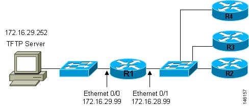
This task uses the network in Figure 7. This task will show how to use AutoInstall to setup routers R2, R3, and R4. Router R1 is the DHCP server that will be used to assign the IP address for Fast Ethernet 0/0 on the new routers during the AutoInstall process.
Figure 7 Network Topology for Assigning AutoInstall Configuration Files For Specific Devices
Every DHCP client has a unique DHCP client identifier. The DHCP client identifier is used by DHCP servers to keep track of IP address leases and for configuring IP address reservations. You need to know the DHCP client identifier for each of the networking devices that you want to configure with AutoInstall so that you can configure the DHCP IP address reservations which will ensure that each device is provided with the correct IP address, and subsequently its unique configuration file. You can determine the DHCP client identifier manually or automatically.
To use AutoInstall to setup routers R2, R3, and R4, perform following tasks:
•![]() Determining the Value for the DHCP Client Identifier Manually
Determining the Value for the DHCP Client Identifier Manually
•![]() Determining the Value for the DHCP Client Identifier Automatically
Determining the Value for the DHCP Client Identifier Automatically
•![]() Creating a Private DHCP Pool for Each of The Routers
Creating a Private DHCP Pool for Each of The Routers
•![]() Creating Configuration Files for Each Router
Creating Configuration Files for Each Router
•![]() Creating the network-confg file
Creating the network-confg file
•![]() Setting Up the Routers with AutoInstall
Setting Up the Routers with AutoInstall
•![]() Saving the Configuration Files on The Routers
Saving the Configuration Files on The Routers
•![]() Removing the Private DHCP Address Pools from R1
Removing the Private DHCP Address Pools from R1
Determining the Value for the DHCP Client Identifier Manually
If you want to determine the value for the client identifiers automatically, you do not need to perform this task. Proceed to the "Determining the Value for the DHCP Client Identifier Automatically" section.
You must know the MAC address of the Fast Ethernet interface that will be used to connect the router to the LAN during the AutoInstall process to determine the client identifier manually. This requires connecting a terminal to the router, and powering it on, so that you can enter the show interface interface-type interface-number command.
The client-identifier looks like this:
0063.6973.636f.2d30.3030.362e.3533.6237.2e38.6537.312d.4661.332f.30
The format is nullcisco-0006.53b7.8e71-fa3/0 where 0006.53b7.8e71 is the MAC address and fa3/0 is the short interface name for the interface that the IP address request is made for.
The values for the short-if-name field can be obtained from an SNMP workstation with the Cisco MIBs installed. This is an example of how to map ifIndex to an interface on Cisco IOS:
snmpwalk -c public ponch ifName
IF-MIB::ifName.1 = STRING: AT2/0
IF-MIB::ifName.2 = STRING: Et0/0
IF-MIB::ifName.3 = STRING: Se0/0
IF-MIB::ifName.4 = STRING: BR0/0
Use the show interface interface-type interface-number command to display the information and statistics for a Fast Ethernet interface.
R6> show interface fastethernet 3/0
FastEthernet3/0 is up, line protocol is up
Hardware is AmdFE, address is 0006.53b7.8e71 (bia 0006.53b7.8e71)
.
.
.
R6>
The MAC address for FastEthernet 3/0 on R6 is 0006.53b7.8e71. The format of the client identifier for this interface is nullcisco-0006.53b7.8e71-fa3/0.
Note ![]() The short interface name for Fast Ethernet interfaces is fa.
The short interface name for Fast Ethernet interfaces is fa.
Table 1 shows the values for converting characters to their hexadecimal equivalents. The last row in Table 2 shows the client identifier for Fast Ethernet 3/0 on R6 (nullcisco-0006.53b7.8e71-fa3/0).
R4
Use the show interface interface-type interface-number command to display the information and statistics for Fast Ethernet 0/0 on R4.
R4> show interface FastEthernet 0/0
FastEthernet0 is up, line protocol is up
Hardware is Lance, address is 00e0.1eb8.eb0e (bia 00e0.1eb8.eb0e)
The MAC address for Fast Ethernet 0/0 on R4 is 00e0.1eb8.eb0e. The format of the client identifier for this interface is nullcisco-00e0.1eb8.eb0e-et0.
Note ![]() The short interface name for Fast Ethernet interfaces is et.
The short interface name for Fast Ethernet interfaces is et.
Using the values for converting characters to their hexadecimal equivalents in Table 1, the client identifier for Fast Ethernet 0/0 on R4 is shown in the last row of Table 3.
R3
Use the show interface interface-type interface-number command to display the information and statistics for Fast Ethernet 0/0 on R3.
R3> show interface FastEthernet 0/0
FastEthernet0 is up, line protocol is up
Hardware is Lance, address is 00e0.1eb8.eb73 (bia 00e0.1eb8.eb73)
The MAC address for Fast Ethernet 0/0 on R3 is 00e0.1eb8.eb73. The format of the client identifier for this interface is: nullcisco-00e0.1eb8.eb73-et0.
Using the values for converting characters to their hexadecimal equivalents in Table 1, the client identifier for Fast Ethernet 0/0 on R3 is shown in the last row of Table 4.
R2
Use the show interface interface-type interface-number command to display the information and statistics for Fast Ethernet 0/0 on R2.
R2> show interface Fast Ethernet 0/0
FastEthernet0/0 is up, line protocol is up
Hardware is Lance, address is 00e0.1eb8.eb09 (bia 00e0.1eb8.eb09)
The MAC address for Fast Ethernet 0/0 on R2 is 00e0.1eb8.eb09. The format of the client identifier for this interface is nullcisco-00e0.1eb8.eb09-et0.
Using the values for converting characters to their hexadecimal equivalents in Table 1, the client identifier for Fast Ethernet 0/0 on R2 is shown in the last row of Table 5
You have now determined the values for the client identifiers on each router. The final step is to add a period after each group of four characters working from the left to the right as shown below:
•![]() R4-0063.6973.636f.2d30.3065.302e.3165.6238.2e65.6230.652d.4574.30
R4-0063.6973.636f.2d30.3065.302e.3165.6238.2e65.6230.652d.4574.30
•![]() R3-0063.6973.636f.2d30.3065.302e.3165.6238.2e65.6237.332d.4574.30
R3-0063.6973.636f.2d30.3065.302e.3165.6238.2e65.6237.332d.4574.30
•![]() R2-0063.6973.636f.2d30.3065.302e.3165.6238.2e65.6230.392d.4574.30
R2-0063.6973.636f.2d30.3065.302e.3165.6238.2e65.6230.392d.4574.30
What to Do Next
Save the values in a text file and proceed to the "Creating a Private DHCP Pool for Each of The Routers" section.
Determining the Value for the DHCP Client Identifier Automatically
If you determined the value for the client identifiers manually, you do not need to perform this task. Proceed to the "Creating a Private DHCP Pool for Each of The Routers" section.
This task will create a DHCP server on R1 that will provide only one IP address. This IP address will used by each new router in sequence while you determine the value of the router's client identifier. By limiting the IP address scope to a single IP address you avoid any possible confusion about which router you are working on. If somebody powers up another router that attempts to start the AutoInstall process, it will not be able to obtain an IP address.
Tip ![]() Do not place the network-confg or router configuration files (r4-confg, r3-confg, or r2-confg) in the root directory of the TFTP server yet. You do not want any of the routers to load these files until you have ensured that each router will obtain the correct IP address from the DHCP server so that the router will load the correct configuration file.
Do not place the network-confg or router configuration files (r4-confg, r3-confg, or r2-confg) in the root directory of the TFTP server yet. You do not want any of the routers to load these files until you have ensured that each router will obtain the correct IP address from the DHCP server so that the router will load the correct configuration file.
This task is broken down into sub-tasks to make it easier to follow (all sub-tasks are required):
•![]() Configuring IP on the Interfaces on R1
Configuring IP on the Interfaces on R1
•![]() Configuring a DHCP Pool on R1
Configuring a DHCP Pool on R1
•![]() Excluding All But One of the IP Addresses from the DHCP Pool on R1
Excluding All But One of the IP Addresses from the DHCP Pool on R1
•![]() Verifying The Configuration on R1
Verifying The Configuration on R1
•![]() Enabling debug ip dhcp server events on R1
Enabling debug ip dhcp server events on R1
•![]() Identifying the Value for the Client Identifier on Each of the Routers
Identifying the Value for the Client Identifier on Each of the Routers
•![]() Removing the DHCP Pool on R1 for Network 172.16.28.0/24
Removing the DHCP Pool on R1 for Network 172.16.28.0/24
•![]() Removing the DHCP Pool on R1 for Network 172.16.28.0/24
Removing the DHCP Pool on R1 for Network 172.16.28.0/24
•![]() Removing the Excluded Address Range From R1
Removing the Excluded Address Range From R1
Configuring IP on the Interfaces on R1
Configure IP addresses on the Fast Ethernet interfaces. Configure the ip helper-address ip-address command on Fast Ethernet 0/1.
!
interface FastEthernet0/0
ip address 172.16.29.99 255.255.255.0
!
interface FastEthernet0/1
ip address 172.16.28.99 255.255.255.0
ip helper-address 172.16.29.252
!
Configuring a DHCP Pool on R1
Configure these commands to setup the temporary DHCP server on R1.
Note ![]() This should be the only DHCP server in operation on R1. This should be the only DHCP server that is accessible by the routers that you will be using AutoInstall to setup.
This should be the only DHCP server in operation on R1. This should be the only DHCP server that is accessible by the routers that you will be using AutoInstall to setup.
!
ip dhcp pool get-client-id
network 172.16.28.0 255.255.255.0
!
Excluding All But One of the IP Addresses from the DHCP Pool on R1
You need to ensure that there is only one IP address available from the DHCP server at any time. Configure the following command to exclude every IP address except 172.16.28.1 from the DHCP pool.
!
ip dhcp excluded-address 172.16.28.2 172.16.28.255
!
Verifying The Configuration on R1
Verify that the configuration file for R1 has a DHCP server pool configured to provide a single IP address (172.16.28.1) to a DHCP client.
Verify that the configuration file has the IP addresses for the Fast Ethernet interfaces and the ip helper-address ip-address command.
!
ip dhcp excluded-address 172.16.28.2 172.16.28.255
!
ip dhcp pool get-client-id
network 172.16.28.0 255.255.255.0
!
interface FastEthernet0/0
ip address 172.16.29.99 255.255.255.0
!
interface FastEthernet0/1
ip address 172.16.28.99 255.255.255.0
ip helper-address 172.16.29.252
!
Enabling debug ip dhcp server events on R1
You use the display output from the debug ip dhcp server events command on the terminal connected to R1 to identify the value of the client identifier for each router.
Enable the debug ip dhcp server events command on R1.
R1# debug ip dhcp server events
Identifying the Value for the Client Identifier on Each of the Routers
This step is repeated for each of the routers. You should only have one of the routers powered-on at any time. When you have identified the value of the client identifier field for the router, you will turn the router off and proceed to the next router.
R4
Connect R4 to the Fast Ethernet network and power it on. The following message will be displayed on the terminal connected to R1 when R4 is assigned the IP address 172.16.28.1.
DHCPD: assigned IP address 172.16.28.1 to client
0063.6973.636f.2d30.3065.302e.3165.6238.2e65.6230.652d.4574.30.
Copy the client identifier 0063.6973.636f.2d30.3065.302e.3165.6238.2e65.6230.652d.4574.30 to a text file and save it. Keep the text file open for the next two routers.
Turn off R4
Release the IP address binding for R4 from the DHCP pool on R1 using the clear ip dhcp binding * command on R1.
R1# clear ip dhcp binding *
R1#
01:16:11: DHCPD: returned 172.16.28.1 to address pool get-client-id.
R3
Connect R3 to the Fast Ethernet network and power it on. The following message will be displayed on the terminal connected to R1 when R3 is assigned the IP address 172.16.28.1.
DHCPD: assigned IP address 172.16.28.1 to client
0063.6973.636f.2d30.3065.302e.3165.6238.2e65.6237.332d.4574.30.
Copy the client identifier 0063.6973.636f.2d30.3065.302e.3165.6238.2e65.6237.332d.4574.30 to the text file and save it. Keep the text file open for the final router.
Turn off R3.
Release the IP address binding for R3 from the DHCP pool on R1 using the clear ip dhcp binding * command on R1.
R1# clear ip dhcp binding *
R1#
01:16:11: DHCPD: returned 172.16.28.1 to address pool get-client-id.
R2
Connect R2 to the Fast Ethernet network and power it on. The following message will be displayed on the terminal connected to R1 when R2 is assigned the IP address 172.16.28.1.
DHCPD: assigned IP address 172.16.28.1 to client
0063.6973.636f.2d30.3065.302e.3165.6238.2e65.6230.392d.4574.30.
Copy the client identifier 0063.6973.636f.2d30.3065.302e.3165.6238.2e65.6230.392d.4574.30 to the text file and save it.
Turn off R2
Release the IP address binding for R2 from the DHCP pool on R1 using the clear ip dhcp binding * command on R1.
R1# clear ip dhcp binding *
R1#
01:16:11: DHCPD: returned 172.16.28.1 to address pool get-client-id.
Client Identifiers for R4, R3, and R2
You have determined the values for the client identifiers on each router.
•![]() R4-0063.6973.636f.2d30.3065.302e.3165.6238.2e65.6230.652d.4574.30
R4-0063.6973.636f.2d30.3065.302e.3165.6238.2e65.6230.652d.4574.30
•![]() R3-0063.6973.636f.2d30.3065.302e.3165.6238.2e65.6237.332d.4574.30
R3-0063.6973.636f.2d30.3065.302e.3165.6238.2e65.6237.332d.4574.30
•![]() R2-0063.6973.636f.2d30.3065.302e.3165.6238.2e65.6230.392d.4574.30
R2-0063.6973.636f.2d30.3065.302e.3165.6238.2e65.6230.392d.4574.30
Removing the DHCP Pool on R1 for Network 172.16.28.0/24
The temporary DHCP pool on the router is no longer required, and must be removed.
R1(config)# no ip dhcp pool get-client-id
Removing the Excluded Address Range From R1
The command for excluding all of the IP addresses except 172.16.28.1 from the DHCP pool on the router is no longer required, and must be removed.
R1(config)# no ip dhcp excluded-address 172.16.28.2 172.16.28.255
Creating a Private DHCP Pool for Each of The Routers
You need to create the private DHCP address pools for each router to ensure that each router is assigned the IP address that maps to its host name in the network-conf file.
!
ip dhcp pool r4
host 172.16.28.100 255.255.255.0
client-identifier 0063.6973.636f.2d30.3065.302e.3165.6238.2e65.6230.652d.4574.30
!
ip dhcp pool r3
host 172.16.28.101 255.255.255.0
client-identifier 0063.6973.636f.2d30.3065.302e.3165.6238.2e65.6237.332d.4574.30
!
ip dhcp pool r2
host 172.16.28.102 255.255.255.0
client-identifier 0063.6973.636f.2d30.3065.302e.3165.6238.2e65.6230.392d.4574.30
Creating Configuration Files for Each Router
Create the configuration files for each router and place them in the root directory of the TFTP server.
Tip ![]() You must include the commands for configuring passwords for remote Telnet access and access to privileged EXEC mode if you are going to access the routers remotely to save their configuration files to NVRAM.
You must include the commands for configuring passwords for remote Telnet access and access to privileged EXEC mode if you are going to access the routers remotely to save their configuration files to NVRAM.
r2-confg
!
hostname R2
!
enable secret 7gD2A0
!
interface FastEthernet0/0
ip address 172.16.28.102 255.255.255.0
!
interface Serial0/0
ip address 192.168.100.1 255.255.255.252
no shutdown
!
interface Serial0/1
ip address 192.168.100.5 255.255.255.252
no shutdown
!
no ip http server
ip classless
ip default-network 0.0.0.0
ip route 0.0.0.0 0.0.0.0 FastEthernet0/0
!
line vty 0 4
password 5Rf1k9
login
!
end
r3-confg
!
hostname R3
!
enable secret 7gD2A0
!
interface FastEthernet0/0
ip address 172.16.28.101 255.255.255.0
!
interface Serial0/0
ip address 192.168.100.9 255.255.255.252
no shutdown
!
interface Serial0/1
ip address 192.168.100.13 255.255.255.252
no shutdown
!
no ip http server
ip classless
ip default-network 0.0.0.0
ip route 0.0.0.0 0.0.0.0 FastEthernet0
!
line vty 0 4
password 5Rf1k9
login
!
end
r4-confg
!
hostname R3
!
enable secret 7gD2A0
!
interface FastEthernet0/0
ip address 172.16.28.101 255.255.255.0
!
interface Serial0/0
ip address 192.168.100.9 255.255.255.252
no shutdown
!
interface Serial0/1
ip address 192.168.100.13 255.255.255.252
no shutdown
!
no ip http server
ip classless
ip default-network 0.0.0.0
ip route 0.0.0.0 0.0.0.0 FastEthernet0/0
!
line vty 0 4
password 5Rf1k9
login
!
end
Creating the network-confg file
Create the network-confg file with the ip host hostname ip-address commands that map the IP addresses that you will be assigning with the DHCP server to the hostname.
ip host r4 172.16.28.100
ip host r3 172.16.28.101
ip host r2 172.16.28.102
Setting Up the Routers with AutoInstall
You are now ready to set up the three routers (R4, R3, and R2) using AutoInstall.
Connect a terminal to the routers if you want to monitor the progress of AutoInstall. Use Hyperterminal or a similar terminal emulation program on your PC, with the following terminal emulation settings, to connect to the device:
•![]() 9600 baud
9600 baud
•![]() 8 data bits, no parity, 1 stop bit
8 data bits, no parity, 1 stop bit
•![]() No flow control
No flow control
You should have the following files in the root directory of the TFTP server.
•![]() network-confg
network-confg
•![]() r4-confg
r4-confg
•![]() r3-confg
r3-confg
•![]() r2-confg
r2-confg
The TFTP server must be running.
Power on each router.
Timesaver ![]() You can set up all three routers concurrently.
You can set up all three routers concurrently.
R4
The following is an excerpt of the messages that are displayed on R4's console terminal during the AutoInstall process:
Loading network-confg from 172.16.29.252 (via FastEthernet0/0): !
[OK - 76 bytes]
Configuration mapped ip address 172.16.28.100 to r4
Loading r4-confg from 172.16.29.252 (via FastEthernet0/0): !
[OK - 687 bytes]
R3
The following is an excerpt of the messages that are displayed on R3's console terminal during the AutoInstall process:
Loading network-confg from 172.16.29.252 (via FastEthernet0/0): !
[OK - 76 bytes]
Configuration mapped ip address 172.16.28.101 to r3
Loading r3-confg from 172.16.29.252 (via FastEthernet0/0): !
[OK - 687 bytes]
R2
The following is an excerpt of the messages that are displayed on R2's console terminal during the AutoInstall process:
Loading network-confg from 172.16.29.252 (via FastEthernet0/0): !
[OK - 76 bytes]
Configuration mapped ip address 172.16.28.102 to r2
Loading r2-confg from 172.16.29.252 (via FastEthernet0/0): !
[OK - 687 bytes]
TFTP Server Log
The TFTP server log should contain messages similar to the following text.
Sent network-confg to (172.16.28.100), 76 bytes
Sent r4-confg to (172.16.28.100),687 bytes
Sent network-confg to (172.16.28.101), 76 bytes
Sent r3-confg to (172.16.28.101),687 bytes
Sent network-confg to (172.16.28.102), 76 bytes
Sent r2-confg to (172.16.28.102),687 bytes
Saving the Configuration Files on The Routers
You must save the running configurations on each router to the startup configuration to ensure that the routers retain their configurations if they are ever power cycled.
R4
R1# telnet 172.16.28.100
Trying 172.16.28.100 ... Open
User Access Verification
Password:
R4> enable
Password:
R4# copy running-config startup-config
Destination filename [startup-config]?
Building configuration...
[OK]
R4# exit
[Connection to 172.16.28.100 closed by foreign host]
R1#
R3
R1# telnet 172.16.28.101
Trying 172.16.28.101 ... Open
User Access Verification
Password:
R3> enable
Password:
R3# copy running-config startup-config
Destination filename [startup-config]?
Building configuration...
[OK]
R3# exit
[Connection to 172.16.28.101 closed by foreign host]
R1#
R2
R1# telnet 172.16.28.102
Trying 172.16.28.102 ... Open
User Access Verification
Password:
R2> enable
Password:
R2# copy running-config startup-config
Destination filename [startup-config]?
Building configuration...
[OK]
R2# exit
[Connection to 172.16.28.102 closed by foreign host]
R1#
Removing the Private DHCP Address Pools from R1
The final step in the AutoInstall process is to remove the private DHCP address pools from R1.
R1(config)# no ip dhcp pool r4
R1(config)# no ip dhcp pool r3
R1(config)# no ip dhcp pool r2
This is the final task, and step for Using AutoInstall to Setup Devices Connected to LANs.
Using AutoInstall to Set Up Devices Connected to WANs: Example
This section contains the following examples:
HDLC WAN Connections
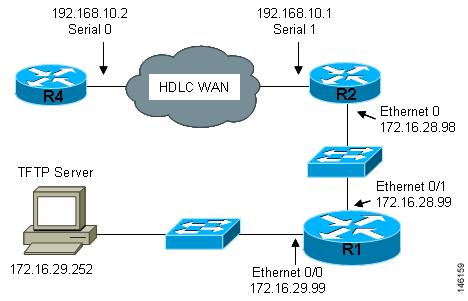
This section uses the network in Figure 8. The section shows how to use AutoInstall to setup R4. R2 will use SLARP to provide R4 the IP address (192.168.20.2) required for AutoInstall.
Figure 8 Network Topology Using AutoInstall to Configure Routers Connected to HDLC WANs
The process for using AutoInstall to set up router R2 requires the following tasks:
•![]() Creating the Configuration for R4
Creating the Configuration for R4
•![]() Creating the network-confg File
Creating the network-confg File
•![]() Setting Up R4 using AutoInstall
Setting Up R4 using AutoInstall
•![]() Save the Configuration File on R4
Save the Configuration File on R4
Creating the Configuration for R4
Create the configuration file for R4 and save it on the TFTP server as r4-confg:
!
hostname R4
!
enable secret 7gD2A0
!
interface FastEthernet0/0
ip address 10.89.45.1 255.255.255.0
no shutdown
!
interface Serial0/0
ip address 192.168.10.2 255.255.255.0
no fair-queue
!
router rip
version 2
network 168.192.0.0
no auto-summary
!
ip http server
ip classless
ip default-network 0.0.0.0
ip route 0.0.0.0 0.0.0.0 Serial0/0
!
line vty 0 4
password 6T2daX9
!
end
Creating the network-confg File
Create the network configuration file for R4 and save it on the TFTP server as network-confg:
ip host r4 192.168.10.2
Configuring R1 and R2
Configure R1 and R2 using the following configurations:
R1
!
hostname R1
!
enable secret 7gD2A0
!
interface FastEthernet0/0
ip address 172.16.29.99 255.255.255.0
!
interface FastEthernet0/1
ip address 172.16.28.99 255.255.255.0
ip helper-address 172.16.29.252
!
router rip
version 2
network 172.16.0.0
no auto-summary
!
ip classless
ip http server
!
line vty 0 4
password 67F2SaB
!
end
R2
!
hostname R2
!
enable secret 7gD2A0
!
interface FastEthernet0/0
ip address 172.16.28.98 255.255.255.0
!
interface Serial0/1
ip address 192.168.10.1 255.255.255.0
clockrate 64000
!
router rip
version 2
network 172.16.0.0
network 192.168.10.0
no auto-summary
!
ip http server
ip classless
!
line vty 0 4
password u58Hg1
!
end
Setting Up R4 using AutoInstall
The network is now ready to use AutoInstall to setup R4. perform the following steps to setup R4.
Connect R4 to the HDLC WAN network.
Power R4 on.
The AutoInstall process should be complete in approximately 5 minutes.
TFTP Server Log
The TFTP server log should contain messages similar to the following text:
Sent network-confg to (192.168.10.2), 76 bytes
Sent r4-confg to (192.168.10.2),687 bytes
Save the Configuration File on R4
You must save the running configurations on R4 to the startup configuration to ensure that R4 retains its configuration if it is ever power cycled.
R1# telnet 192.168.10.2
Trying 192.168.10.2 ... Open
User Access Verification
Password:
R4> enable
Password:
R4# copy running-config startup-config
Destination filename [startup-config]?
Building configuration...
[OK]
R4# exit
[Connection to 192.168.10.2 closed by foreign host]
R1#
Frame-Relay WAN Connections
This section uses the network in Figure 9. The section shows how to use AutoInstall to setup R4. R2 will use BOOTP to provide R4 the IP address (172.16.27.100) required for AutoInstall.
R2 uses 172.16.27.100 as the IP address to provide to R3 using BOOTP because this is the IP address in the frame-relay map ip 172.16.27.100 100 broadcast command on serial 0 that points to serial 0 on R3.
Figure 9 Network Topology for Using AutoInstall to Configure Routers Connected to Frame Relay WANs
The process for using AutoInstall to set up router R3 requires the following tasks:
•![]() Creating the Configuration for R3
Creating the Configuration for R3
•![]() Creating the network-confg File
Creating the network-confg File
•![]() Setting Up R3 using AutoInstall
Setting Up R3 using AutoInstall
•![]() Saving the Configuration File on R3
Saving the Configuration File on R3
Creating the Configuration for R3
Create the configuration file for R4 and save it on the TFTP server as r3-confg:
!
hostname R3
!
enable secret 8Hg5Zc20
!
interface FastEthernet0/0
no ip address
shutdown
!
interface Serial0/0
ip address 172.16.27.100 255.255.255.0
encapsulation frame-relay IETF
no fair-queue
frame-relay map ip 172.16.27.99 101 broadcast
frame-relay interface-dlci 101
!
interface Serial0/1
no ip address
shutdown
!
router rip
version 2
network 172.16.0.0
no auto-summary
!
line vty 0 4
password 67Td3a
login
!
end
Creating the network-confg File
Create the network configuration file for R3 and save in on the TFTP server as network-confg:
ip host r3 172.16.27.100
Configuring R1 and R2
Configure R1 and R2 using the following configurations:
R1
!
hostname R1
!
enable secret 86vC7Z
!
interface FastEthernet0/0
ip address 172.16.29.99 255.255.255.0
!
interface FastEthernet0/1
ip address 172.16.28.99 255.255.255.0
!
router rip
version 2
network 172.16.0.0
no auto-summary
!
line vty 0 4
password 6Gu8z0s
!
!
end
R2
!
hostname R2
!
enable secret 67Hfc5z2
!
interface FastEthernet0/0
ip address 172.16.28.98 255.255.255.0
ip helper-address 172.16.29.252
!
interface Serial0/0
ip address 172.16.27.99 255.255.255.0
ip helper-address 172.16.29.252
encapsulation frame-relay IETF
no fair-queue
frame-relay map ip 172.16.27.100 100 broadcast
frame-relay interface-dlci 100
!
interface Serial1
no ip address
!
router rip
version 2
network 172.16.0.0
no auto-summary
!
line vty 0 4
password 9Jb6Z3g
!
end
Setting Up R3 using AutoInstall
The network is now ready to use AutoInstall to set up R3. perform the following steps to setup R4.
Connect R3 to the Frame Relay network.
Power R3 on.
The AutoInstall process should be complete in approximately 5 minutes.
TFTP Server Log
The TFTP server log should contain messages similar to the following text:
Sent network-confg to (172.16.27.100), 76 bytes
Sent r3-confg to (172.16.27.100),687 bytes
Saving the Configuration File on R3
You must save the running configurations on R3 to the startup configuration to ensure that R3 retains its configuration if it is ever power cycled.
R1# telnet 172.16.27.100
Trying 172.16.27.100 ... Open
User Access Verification
Password:
R3> enable
Password:
R3# copy running-config startup-config
Destination filename [startup-config]?
Building configuration...
[OK]
R4# exit
[Connection to 192.168.10.2 closed by foreign host]
R1#
Additional References
The following sections provide references related to Using AutoInstall to Remotely Configure Cisco Networking Devices.
Related Documents
|
|
|
|---|---|
Overview of Cisco IOS Setup Mode and AutoInstall for configuring Cisco networking devices |
|
Using Setup Mode to Configure a Cisco Networking Device |
MIBs
RFCs
|
|
|
|---|---|
No new or modified RFCs are supported by this feature, and support for existing RFCs has not been modified by this feature |
— |
Technical Assistance
Feature Information for Using AutoInstall to Remotely Configure a Cisco Networking Device
Table 6 lists the features in this module and provides links to specific configuration information.
Use Cisco Feature Navigator to find information about platform support and software image support. Cisco Feature Navigator enables you to determine which Cisco IOS XE software images support a specific software release, feature set, or platform. To access Cisco Feature Navigator, go to http://www.cisco.com/go/cfn. An account on Cisco.com is not required.
Note ![]() Table 6 lists only the Cisco IOS XE software release that introduced support for a given feature in a given Cisco IOS XE software release train. Unless noted otherwise, subsequent releases of that Cisco IOS XE software release train also support that feature.
Table 6 lists only the Cisco IOS XE software release that introduced support for a given feature in a given Cisco IOS XE software release train. Unless noted otherwise, subsequent releases of that Cisco IOS XE software release train also support that feature.
|
|
|
|
|---|---|---|
AutoInstall Using DHCP for LAN Interfaces |
Cisco IOS XE Release 2.1 |
The AutoInstall Using DHCP for LAN Interfaces feature enhances the benefits of AutoInstall by replacing the use of the Bootstrap Protocol (BOOTP) with the use of the Dynamic Host Configuration Protocol (DHCP) for Cisco IOS AutoInstall over LAN interfaces (specifically Fast Ethernet, Token Ring, and FDDI interfaces). In Cisco IOS XE Release 2.1, this feature was introduced on Cisco ASR 1000 Series Routers. The following section provides information about this feature: • |
 Feedback