Configuring and Applying OER Policies
Available Languages
Table Of Contents
Configuring and Applying OER Policies
Prerequisites for Configuring and Applying OER Policies
Information About Configuring and Applying OER Policies
OER Apply Policy Phase Overview
OER Traffic Class Performance Policies
Performance Routing Link Grouping
OER Policy Operational Options and Parameters
Priority Resolution for Multiple OER Policies
How to Configure and Apply OER Policies
Configuring and Applying an OER Policy to Learned Traffic Classes
Cisco IOS OER Timers Adjustments
Configuring and Applying an OER Policy to Configured Traffic Classes
Cisco IOS OER Timers Adjustments
Preventing OER Optimization of Learned Prefixes
Configuring and Applying an OER Policy to Learned Inside Prefixes
Configuring and Applying an OER Policy to Configured Inside Prefixes
Configuring Policy Rules for OER Maps
Configuring Multiple OER Policy Conflict Resolution
Configuring an Exit Link Load Balancing OER Policy
Implementing Performance Routing Link Groups
Configuring OER Cost-Based Policies
Configuring OER Network Security Policies
Configuring Black Hole Routing Using an OER Map
Configuring Sinkhole Routing Using an OER Map
Configuring OER Voice Traffic Optimization Using Active Probes
Identifying Traffic for OER Using a Prefix List
Identifying Voice Traffic to Optimize Using an Access List
Configuring OER Voice Probes with a Target Assignment
Configuration Examples for Configuring and Applying OER Policies
Configuring and Applying an OER Policy to Learned Traffic Classes: Example
Configuring and Applying an OER Policy to Configured Traffic Classes: Example
Preventing OER Optimization of Learned Prefixes: Example
Configuring and Applying an OER Policy to Learned Inside Prefixes: Example
Configuring and Applying an OER Policy to Configured Inside Prefixes: Example
Configuring Policy Rules for OER Maps: Example
Configuring Multiple OER Policy Conflict Resolution: Example
Configuring an Exit Link Load Balancing OER Policy: Example
Implementing Performance Routing Link Groups: Example
Configuring OER Cost-Based Policies: Example
Configuring OER Network Security Policies: Examples
Configuring OER Voice Traffic Optimization Using Active Probes: Examples
Optimizing Only Voice Traffic Using Active Probes
Optimizing Traffic (Including Voice Traffic) Using Active Probes
Feature Information for Configuring and Applying OER Policies
Configuring and Applying OER Policies
First Published: January 29, 2007Last Updated: July 19, 2007This module describes the Cisco IOS Optimized Edge Routing (OER) apply policy phase. In the apply policy phase, OER uses policies to map the measured performance metrics of traffic class entries in the Monitored Traffic Class (MTC) list, or exit links, against well-known or configured thresholds to determine if the traffic class entry performance or the link utilization is meeting specified levels of service, or if some action is required.
Finding Feature Information in This Module
Your Cisco IOS software release may not support all of the features documented in this module. To reach links to specific feature documentation in this module and to see a list of the releases in which each feature is supported, use the "Feature Information for Configuring and Applying OER Policies" section.
Finding Support Information for Platforms and Cisco IOS and Catalyst OS Software Images
Use Cisco Feature Navigator to find information about platform support and Cisco IOS and Catalyst OS software image support. To access Cisco Feature Navigator, go to http://www.cisco.com/go/cfn. An account on Cisco.com is not required.
Contents
•
Prerequisites for Configuring and Applying OER Policies
•
•
•
•
Prerequisites for Configuring and Applying OER Policies
Before implementing OER policies, you need to understand an overview of how OER works and how to set up OER network components. See the "Cisco IOS Optimized Edge Routing Overview" and "Setting Up OER Network Components" modules for more details. If you are following the OER performance loop, the OER profile and measure phases precede this phase. See the "Where to Go Next" section for more details.
Information About Configuring and Applying OER Policies
To configure and apply OER policies, you should understand the following concepts:
•
•
•
•
•
•
OER Apply Policy Phase Overview
The OER apply policy phase is the third step in the OER performance loop following after the profile phase that identifies the traffic classes, and the measure phase where each traffic class entry in the MTC list is monitored to determine performance metric measurements. The apply policy phase compares the measured performance metrics against well-known or configured thresholds to determine if the traffic is meeting specified levels of service, or if some action is required. If the performance metric does not conform to the threshold, a decision is made by OER to move the traffic class or exit into another state. For more details about the state transition decision, see the "OER Policy Decision Point" section.
An OER policy is a rule that defines an objective and contains the following attributes:
•
•
•
For example, a policy can be configured to maintain a delay of less than or equal to 100 milliseconds for packets sent to a specific traffic class entry. The scope is the network traffic sent to the specific traffic class entry, the action is a routing table change, and the triggering event is a measured delay of greater than 100 milliseconds for this traffic. The action may be not be executed until OER is configured to control the traffic in the OER control phase. By default, OER runs in an observe mode during the profile, measure, and apply policy phases.
In the OER apply policy phase you can configure and apply policies. Different types of OER policies can be configured—see Figure 1—and specific OER parameters and options can be included within a policy. In this document, a parameter is a configurable element that can be fine-tuned, and an option is a configurable element that is either enabled or disabled. After an OER policy is configured, the policy can be applied to learned traffic classes or configured traffic classes. OER policies can be applied globally—to all the traffic classes—or to just a specific set of traffic classes.
Figure 1 OER Apply Policy Phase Structure
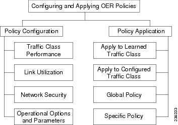
In Figure 1 you can see that there are three types of OER policies plus some operational options and parameters that can be configured. Use the following links to review more information about each policy type, parameter, or option:
•
•
•
After an OER policy is configured, you can see from Figure 1 that a policy can be applied to learned traffic classes or configured traffic classes on a global basis for all traffic classes or for a specific set of traffic classes. For more details about applying OER policies, see the "OER Policy Application" section.
When configuring multiple policy parameters for traffic classes, it is possible to have multiple overlapping policies. To resolve the potential conflict of which policy to run, OER uses its resolve function: a flexible mechanism that allows you to set the priority for most of the policy types. For more details about how OER resolves multiple policy conflicts, see the "Priority Resolution for Multiple OER Policies" section.
OER Policy Decision Point
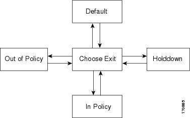
When running an OER policy that compares the traffic class performance metrics with default or configured thresholds, a traffic class may change state. OER uses a policy decision point (PDP) that operates according to the traffic class state transition diagram shown in Figure 2. The state transition diagram in Figure 2 contains the following states:
•
•
•
Figure 2 OER Traffic Class State Transition Diagram
•
•
OER Traffic Class Performance Policies
OER traffic class performance policies are a set of rules that govern performance characteristics for traffic classes that can be network addresses (prefixes) or application criteria such as protocol, port number, or DSCP value. Network addresses can refer to individual endpoints within a network (e.g. 10.1.1.1/32) or to entire subnets (e.g. 10.0.0.0/8). The major performance characteristics that can be managed within an OER policy are:
With the exception of reachability, none of these performance characteristics can be managed within the constructs of conventional routing protocol metrics. Cisco OER extends the concept of reachability (beyond ensuring that a particular route exists in the routing table) by automatically verifying that the destination can be reached through the indicated path. Using Cisco OER provides the network administrator with a new and powerful toolset for managing the flow of traffic.
Reachability
Reachability is specified as the relative percentage or the absolute maximum number of unreachable hosts, based on flows per million (fpm), that OER will permit from a traffic class entry. If the absolute number or relative percentage of unreachable hosts is greater than the user-defined or the default value, OER determines that the traffic class entry is out-of-policy and searches for an alternate exit link.
To configure parameters for reachability, use the unreachable command. This command has two keywords, relative and threshold. The relative keyword is used to configure the relative percentage of unreachable hosts. The relative unreachable host percentage is based on a comparison of short-term and long-term measurements. The short-term measurement reflects the percentage of hosts that are unreachable within a 5-minute period. The long-term measurement reflects the percentage of unreachable hosts within a 60-minute period. The following formula is used to calculate this value:
Relative percentage of unreachable hosts = ((short-term percentage - long-term percentage) / long-term percentage) * 100
The master controller measures the difference between these two values as a percentage. If the percentage exceeds the user-defined or default value, the traffic class entry is determined to be out-of-policy. For example, if 10 hosts are unreachable during the long-term measurement and 12 hosts are unreachable during short-term measurement, the relative percentage of unreachable hosts is 20 percent.
The threshold keyword is used to configure the absolute maximum number of unreachable hosts. The maximum value is based on the actual number of hosts that are unreachable based on fpm.
Delay
Delay (also referred as latency) is defined as the delay between when the packet was sent from the source device and when it arrived at a destination device. Delay can be measured as one-way delay or round-trip delay. The largest contributor to latency is caused by network transmission delay.
In Cisco IOS Release 12.4(6)T, 12.2(33)SRB, and later releases, support was introduced for defining delay performance characteristics with respect to voice traffic. Round-trip delay affects the dynamics of conversation and is used in Mean Opinion Score (MOS) calculations. One-way delay is used for diagnosing network problems. A caller may notice a delay of 200 milliseconds and try to speak just as the other person is replying because of packet delay. The telephone industry standard specified in ITU-T G.114 recommends the maximum desired one-way delay be no more than 150 milliseconds. Beyond a one-way delay of 150 milliseconds, voice quality is affected. With a round-trip delay of 300 milliseconds or more, users may experience annoying talk-over effects.
Packet Loss
Packet loss can occur due an interface failing, a packet being routed to the wrong destination, or congestion in the network.
Packet loss for voice traffic leads to the degradation of service in which a caller hears the voice sound with breaks. Although average packet loss is low, voice quality may be affected by a short series of lost packets.
Jitter
Support for jitter was introduced in Cisco IOS Release 12.4(6)T, 12.2(33)SRB, and later releases. Jitter means interpacket delay variance. When multiple packets are sent consecutively from source to destination, for example, 10 ms apart, and if the network is behaving ideally, the destination should be receiving them 10 ms apart. But if there are delays in the network (like queuing, arriving through alternate routes, and so on) the arrival delay between packets might be greater than or less than 10 ms. Using this example, a positive jitter value indicates that the packets arrived more than 10 ms apart. If the packets arrive 12 ms apart, then positive jitter is 2 ms; if the packets arrive 8 ms apart, then negative jitter is 2 ms. For delay-sensitive networks like VoIP, both positive and negative jitter values are undesirable; a jitter value of 0 is ideal.
Mean Opinion Score (MOS)
Support for MOS was introduced in Cisco IOS Release 12.4(6)T, 12.2(33)SRB, and later releases. With all the factors affecting voice quality, many people ask how voice quality can be measured. Standards bodies like the ITU have derived two important recommendations: P.800 (MOS) and P.861 (Perceptual Speech Quality Measurement [PSQM]). P.800 is concerned with defining a method to derive a Mean Opinion Score of voice quality. MOS scores range between 1 representing the worst voice quality, and 5 representing the best voice quality. A MOS of 4 is considered "toll-quality" voice.
In Cisco IOS Release 12.4(4)T and prior releases, only reachability, delay, and loss performance characteristics could be used. In Cisco IOS Release 12.4(6)T, 12.2(33)SRB, and later releases, jitter and MOS performance characteristic can be configured in an OER policy as well as delay and packet loss to determine the quality of a phone call over an IP network.
OER Link Policies
OER link policies are a set of rules that are applied against OER-managed external link (an external link is an interface on a border router on the network edge). Link policies define the desired performance characteristics of the links. Instead of defining the performance of an individual traffic class entry that uses the link (as in traffic class performance policies), link policies are concerned with the performance of the link as a whole. In Cisco IOS Release 12.4(6)T and prior releases, link policies are applied only to exit (egress) links, but in Cisco IOS Release 12.4(9)T, 12.2(33)SRB, and later releases, support for selected entrance (ingress) link policies was introduced. The following performance characteristics are managed by link policies:
•
•
•
Traffic Load
A traffic load (also referred to as utilization) policy consists of an upper threshold on the amount of traffic that a specific link can carry. Cisco IOS OER supports per traffic class load distribution. Every 20 seconds, by default, the border router reports the link utilization to the master controller, after an external interface is configured for a border router. In Cisco IOS Release 12.4(6)T and prior releases, only exit link traffic load thresholds can be configured as an OER policy, but in Cisco IOS Release 12.4(9)T, 12.2(33)SRB, and later releases, entrance link traffic load thresholds can be configured. If the exit or entrance link utilization is above the configured threshold, or the default threshold of 75 percent, the exit or entrance link is in an OOP state and OER starts the monitoring process to find an alternative link for the traffic class. The link utilization threshold can be manually configured either as an absolute value in kilobytes per second (kbps) or as a percentage. A load utilization policy for an individual interface is configured on the master controller under the border router configuration.

Tip
Range
A range policy is defined to maintain all links within a certain utilization range, relative to each other in order to ensure that the traffic load is distributed. For example, if a network has multiple exit links, and there is no financial reason to choose one link over another, the optimal choice is to provide an even load distribution across all links. The load-sharing provided by traditional routing protocols is not always evenly distributed, because the load-sharing is flow-based rather than performance- or policy-based. Cisco OER range functionality allows you to configure OER to maintain the traffic utilization on a set of links within a certain percentage range of each other. If the difference between the links becomes too great, OER will attempt to bring the link back to an in-policy state by distributing traffic classes among the available links. The master controller sets the maximum range utilization to 20 percent for all OER-managed links by default, but the utilization range can be configured using a maximum percentage value. In Cisco IOS Release 12.4(6)T and prior releases, only an exit link utilization range can be configured as an OER policy, but in Cisco IOS Release 12.4(9)T, 12.2(33)SRB, and later releases, an entrance link utilization range can be configured.
Cost
OER support for cost-based optimization was introduced in Cisco IOS Release 12.3(14)T and 12.2(33)SRB. Cost-based optimization allow you to configure policies based on the monetary cost (ISP service level agreements [SLAs]) of each exit link in your network. To implement OER cost-based optimization the OER master controller is configured to send traffic over exit links that provide the most cost-effective bandwidth utilization, while still maintaining the desired performance characteristics. Cost-based optimization supports two billing models: fixed-rate billing or tier-based billing.
Fixed-rate billing is used when the ISP bills one flat rate for network access regardless of bandwidth usage. If fixed-rate billing only is configured on the exit links, all exits are considered equal with regard to cost-optimization and other policy parameters (such as delay, loss, and utilization) that are used to determine if the prefix or exit link is in-policy.
If multiple exit links are configured with tiered and fixed policies, then exit links with fixed policies have the highest priority with regard to cost optimization. If the fixed exit links are at maximum utilization, then the tiered exit links will be used.
Tier-based billing is used when the ISP bills at a tiered rate based on the percentage of exit link utilization. Each cost tier is configured separately with an associated monetary cost and a percentage of bandwidth utilization that activates the tier is defined. An allowance is made for bursting in the algorithm used to determine the tier-based billing. Bursting is defined as short periods of high bandwidth usage that would be expensive under fixed-rate billing.
The specific details of tier-based billing models vary by ISP. However, most ISPs use some variation of the following algorithm to calculate what an enterprise should pay in a tiered billing plan:
•
•
•
•
•
•

Note
At the end of each billing cycle the top n percent of samples, or rollup values, are discarded. The remaining highest value is the sustained utilization. Based on the number of samples discarded, the billing cycle is divided into three periods: the initial period, the middle period, and the last period.
The initial period is when the number of samples measured is less than the number of discards +1. For example, if the discard percentage is 7 percent, billing month is 30 days long, and sample period is 24 hours, then there are 30 samples at the end of the month. The number of discard samples is two (7 percent of 30). In this case, days one, two, and three are in the initial period. During this period, target the lowest tier for each ISP at the start of each respective billing period and "walk up" the tiers until the current total amount of traffic is allocated across the links.
The middle period is after the initial period until the number of samples yet to be measured or collected is less than the number of discards. Using the same example as before, the middle period occurs from day four through day 28. During this period, set the target tier to the sustained utilization tier, which is the tier in which (discard +1) the highest sample so far measured falls.
The period after the middle period until the end of billing period is the last period. During this period, if you used links at the maximum link capacity for the remainder of the billing period and sustained utilization did not change, then set the target to the maximum allowable link utilization. Maximum link utilization is configurable where most likely values are 75 to 90 percent. Otherwise, set the target to sustained utilization tier.
During any sample period, if the cumulative usage is more than targeted cumulative usage, then bump up to the next tier for the remainder of sample period. If rollup is enabled, then replace the sample values with rollup values, and replace the number of samples with the number of rollups in the cost optimization algorithm.
Performance Routing Link Grouping
In Cisco IOS Release 12.4(15)T the ability to define a group of exit links as a preferred set of links, or a fallback set of links for OER to use when optimizing traffic classes specified in an OER policy, was introduced. OER currently selects the best link for a traffic class based on the preferences specified in a policy and the traffic class performance—using parameters such as reachability, delay, loss, jitter or MOS—on a path out of the specified link. Bandwidth utilization, cost, and the range of links can also be considered in selecting the best link. Link grouping introduces a method of specifying preferred links for one or more traffic classes in an OER policy so that the traffic classes are routed through the best link from a list of preferred links, referred to as the primary link group. A fallback link group can also be specified in case there are no links in the primary group that satisfy the specified policy and performance requirements. If no primary group links are available, the traffic classes are routed through the best link from the fallback group. To identify the best exit, OER probes links from both the primary and fallback groups.
Primary and fallback link groups can be configured at the master controller and are identified using a unique name. Link groups provide a method of grouping links such as high bandwidth links to be used, for example, by video traffic, by configuring an OER policy to specify that the best link is to be selected from the link group that consists of only high bandwidth links. The traffic classes specified in a policy can be configured with only one primary link group and one fallback link group. The priority of a link group can vary between policies, a link group might be a primary link group for one policy, and a fallback link group for another policy.
See Figure 3 for an example of how to implement link grouping. Three link groups, ISP1, ISP2, and ISP3 represent different Internet Service Providers (ISPs) and all three ISPs have links to interfaces on the three border routers shown in Figure 3. ISP1 links are the most expensive links, but they have the best Service Level Agreement (SLA) guarantees. ISP3 links are best effort links, and these links are the cheapest links. ISP2 links are not as good as the ISP1 links, but the ISP2 links are more reliable than the ISP3 links. The cost of the ISP2 links is higher than the ISP3 links, but lower than ISP1 links. In this situation, each ISP is created as a link group and associated with an interface on each border router shown in Figure 3.
Figure 3 Link Group Diagram
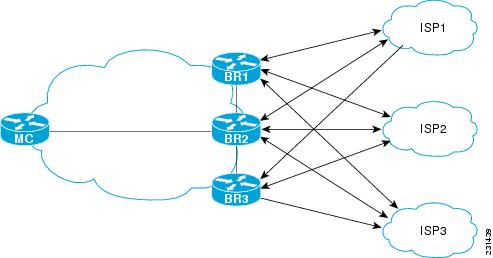
Assuming four types of traffic class, video, voice, FTP, and data, each traffic class can be routed through a border router interface belonging to an appropriate link group. Video and voice traffic classes need the best links so the ISP1 link group is configured as the primary link group, with ISP2 as the fallback group. FTP traffic needs reliable links but the cost might be a factor so ISP2 is assigned as the primary group, and ISP3 is the fallback link group. Note that although ISP1 provides the most reliable links, it may be too expensive for file transfer traffic. For data traffic, ISP3 is a good choice as a primary link group, with ISP2 as the fallback group.
Spillover
Performance routing link groups can be used to support spillover. Spillover is when there are two paths through the network—traffic engineering (TE) tunnels, for example—to the same provider edge (PE) router, but the tunnels take different paths across the network and the traffic is sent through one tunnel until it reaches a traffic load threshold when it spills over to the second tunnel. Using OER link groups one tunnel is created as a primary link group and the second tunnel is the fallback link group. When the first tunnel goes out of policy, OER switches to the fallback tunnel link group, which provides the spillover capacity until the traffic load on the first tunnel drops below the threshold. The tunnels must be established before the OER link groups are configured.
OER Network Security Policies
The ability to configure network security policies either to prevent unauthorized use of the network or to mitigate attacks inside and outside the network was introduced in Cisco IOS Release 12.4(6)T and 12.2(33)SRB. You can configure OER to use black hole or sinkhole routing techniques to limit the impact of attacks against your network. Black hole routing refers to the process of forwarding packets to a null interface, meaning that the packets are dropped into a "black hole." Sinkhole routing directs packets to a next hop where the packets can be stored, analyzed, or dropped. Another term for sinkhole routing is honey-pot routing.
OER Policy Operational Options and Parameters
In addition to the specific types of OER policies, there are some OER policy operational parameters or options that can be configured. The operational parameters are timers and the operational options consist of different operational modes. For more details, see the following sections:
OER Timers Parameters
Three types of timers can be configured as OER policy operational parameters:
Backoff Timer
The backoff timer is used to adjust the transition period that the master controller holds an out-of-policy traffic class entry. The master controller waits for the transition period before making an attempt to find an in-policy exit. A minimum, a maximum, and an optional step timer value can be configured.
Holddown Timer
The holddown timer is used to configure the traffic class entry route dampening timer to set the minimum period of time that a new exit must be used before an alternate exit can be selected. To prevent the traffic class entry from flapping because of rapid state changes, the master controller does not move the traffic class entry to a different exit even if it goes out-of-policy during the holddown timer period. OER does not implement policy changes while a traffic class entry is in the holddown state. A traffic class entry will remain in a holddown state for the default or configured time period. When the holddown timer expires, OER will select the best exit based on performance and policy configuration. However, an immediate route change will be triggered if the current exit for a traffic class entry becomes unreachable.
Periodic Timer
The periodic timer is used to find a better path for a traffic class entry, even if the traffic class entry is in-policy on the current exit. When the periodic timer expires, the master controller evaluates current exit links for the traffic class entry and, if a better exit exists based on the current measurements and priorities, the traffic class entry is moved to a new in-policy exit link.
When adjusting OER timers note that a newly configured timer setting will immediately replace the existing setting if the value of the new setting is less than the time remaining. If the value is greater than the time remaining, the new setting will be applied when the existing timer expires or is reset.
Note
OER Mode Options
Three types of mode options can be configured as OER policy operational options:
Mode Monitor
The mode monitor option enables the configuration of OER monitoring settings. Monitoring is defined here as the act of measurement performed periodically over a set interval of time where the measurements are compared against a threshold. OER measures the performance of traffic classes using active and passive monitoring techniques but it also measures, by default, the utilization of exit links. For more details about mode monitoring options, see the "Measuring the Traffic Class Performance and Link Utilization Using OER" module.
Mode Route
The mode route option specifies one of three OER route control policy settings. Mode route control enables OER to control routes automatically, mode route metric specifies OER route protocol-related settings, and mode route observe offers route control advice, but does not take any action. Observe mode monitoring is enabled by default when OER is enabled. In observe mode, the master controller monitors traffic classes and exit links based on default and user-defined policies and then reports the status of the network and the decisions that should be made but does not implement any changes. Observe mode is used to verify the effect of OER features before OER is actively deployed on your network. For more details about the mode route control and mode route metric options, see the "Using OER to Control the Traffic Classes and Verify the Network Performance" module.
Mode Select-Exit
The mode select-exit option enables the exit selection settings. The definition of an in-policy traffic class entry is that the measured performance metrics are do not exceed a default or configured threshold while the traffic class traffic is on the current path. In this situation, OER does not search for an alternate exit link because the current network path keeps the traffic class entry in-policy. This type of configuration would be activated by using the mode select-link good command which is the default if the mode command is not specified. There are other deployment scenarios, where OER selects the best performance path. This type of configuration can be activated by using the mode select-link best command. In this type of situation, OER measures alternate path performance metrics while the traffic class entry is in-policy on the current path. OER moves the current path if a better performance path is found. After the first selection of the best path, however, OER does not initiate another search unless the periodic timer is configured. When the periodic timer expires, the master controller evaluates current exit links for the traffic class entry and, if a better exit exists based on the current measurements and priorities, the traffic class entry is moved to a new in-policy exit link. Use the periodic timer with the mode select-link best command if you have a deployment scenario where you need OER to select the best performance path at any given time.
There is one further use of the mode select-exit option. If OER does not find an in-policy exit for a traffic class entry when the mode select-link good command is operational, OER transitions the traffic class entry to an uncontrolled state. If OER does not find an in-policy exit for a traffic class entry when the mode select-link best command is operational, OER selects the best of the OOP exit links for the traffic class entry.
OER Policy Application
OER policies can be applied to learned or configured traffic classes. OER policies can be applied on a global basis when the policy is configured directly under OER master controller configuration mode. All traffic classes inherit global policies. If, however, you want to apply a policy to a subset of the traffic classes, then a specific policy can be configured. A specific OER policy applies only to the specific traffic classes that match a prefix list or access list. Specific policies inherit global policies unless the same policy is overwritten by the specific policy. In Cisco IOS Release 12.4(6)T and earlier releases, OER policies applied only to prefixes, but in Cisco IOS Release 12.4(9)T, 12.2(33)SRB, and later releases, OER policies can apply to traffic classes that define an application traffic class and may include prefixes, protocols, port numbers, and DSCP values. To apply specific policies to learned or configured traffic classes, OER map configuration is used.
OER Map Configuration for OER Policies
An OER map may appear to be similar to a route map but there are significant differences. An OER map is designed to select learned or configured traffic classes using a match clause and then to apply OER policy configurations using a set clause. The OER map can be optionally configured with a sequence number like a route map, but only the OER map with the lowest sequence number is evaluated. The operation of an OER map differs from a route map at this point. There are two important distinctions:
•
•
The OER map applies the configuration of the set clause after a successful match occurs. An OER set clause can be used to set policy parameters such as the backoff timer, packet delay, holddown timer, packet loss, mode settings, periodic timer, resolve settings, unreachable hosts, and traceroute reporting.
Policies applied by an OER map take effect immediately. The OER map configuration can be viewed in the output of the show running-config command. OER policy configuration can be viewed in the output of the show oer master policy command. These policies are applied only to traffic classes that match or pass through the OER map.
Policy Rules Configuration to Apply an OER Policy
The policy-rules OER master controller configuration command was introduced in Cisco IOS Release 12.3(11)T, 12.2(33)SRB, and later releases. This command allows you to select an OER map using a sequence number and apply the configuration under OER master controller configuration mode, providing an improved method to switch between predefined OER maps. Only one OER map is used at a time for policy configuration, but many OER maps can be defined. In Cisco IOS Release 12.3(8)T, only one OER map could be defined to apply a policy to traffic classes.
Priority Resolution for Multiple OER Policies
When configuring multiple policy criteria for a single traffic class entry, or a set of traffic classes, it is possible to have multiple overlapping policies. To resolve the potential conflict of which policy to run, OER uses its resolve function: a flexible mechanism that allows you to set the priority for an OER policy. Each policy is assigned a unique value, and the policy with the lowest value is selected as the highest priority policy. By default, OER assigns the highest priority to delay policies, followed by utilization policies. Assigning a priority value to any policy will override the default settings. To configure the policy conflict resolution, use the resolve command in OER master controller configuration mode, or the set resolve command in OER map configuration mode.
Variance Setting for OER Policy Conflict Resolution
When configuring OER resolve settings, you can also set an allowable variance for the defined policy. Variance configures the average delay, as a percentage, that all traffic classes for one exit, or the specific policy traffic classes for an exit, can vary from the defined policy value and still be considered equivalent. For example, if the delay on the best exit link (best exit in terms of delay) for a traffic class entry is 80 milliseconds (ms) and a 10 percent variance is configured, then any other exit links with a delay between 80 and 88 ms for the same traffic class entry are considered equivalent to the best exit link.
To illustrate how variance is used by OER consider three exit links with the following performance values for delay and jitter for a traffic class entry:
•
•
•
The following OER policy conflict resolution is configured and applied to the traffic class entry:
delay priority 1 variance 10jitter priority 2 variance 10OER determines the best exit by looking at the policy with the lowest priority value, which in this example is the delay policy. Exit A has the lowest delay value, but Exit B has a delay value of 85 which is within a 10 percent variance of the delay value at Exit A. Exit A and Exit B can therefore be considered equal in terms of delay values. Exit C is now eliminated because the delay values are too high. The next priority policy is jitter, and Exit B has the lowest jitter value. OER will select Exit B as the only best exit for the traffic class entry because Exit A has a jitter value that is not within 10 percent variance of the Exit B jitter value.
Note
How to Configure and Apply OER Policies
This section contains the following optional tasks:
•
•
•
•
•
•
•
•
•
•
•
•
Configuring and Applying an OER Policy to Learned Traffic Classes
Perform this task at the master controller to configure and apply an OER policy to learned traffic classes. After configuring the router as an OER master controller using the oer master command, most of the commands in this task are all optional. Each step configures a performance policy that applies to learned traffic classes on a global basis. In this example, OER is configured to select the first in-policy exit.
Cisco IOS OER Timers Adjustments
When adjusting OER timers note that a newly configured timer setting will immediately replace the existing setting if the value of the new setting is less than the time remaining. If the value is greater than the time remaining, the new setting will be applied when the existing timer expires or is reset.
Note
SUMMARY STEPS
1.
2.
3.
4.
5.
6.
7.
8.
9.
10.
11.
12.
DETAILED STEPS
Step 1
enable
Example:Router> enable
Enables privileged EXEC mode.
•
Step 2
configure terminal
Example:Router# configure terminal
Enters global configuration mode.
Step 3
oer master
Example:Router(config)# oer master
Enters OER master controller configuration mode.
Step 4
backoff min-timer max-timer [step-timer]
Example:Router(config-oer-mc)# backoff 400 4000 400
(Optional) Sets the backoff timer to adjust the time period for policy decisions.
•
•
•
Step 5
delay {relative percentage | threshold maximum}
Example:Router(config-oer-mc)# delay relative 80
(Optional) Sets the delay threshold as a relative percentage or as an absolute value.
•
•
•
•
Step 6
holddown timer
Example:Router(config-oer-mc)# holddown 600
(Optional) Configures the traffic class entry route dampening timer to set the minimum period of time that a new exit must be used before an alternate exit can be selected.
•
•
•
•
Step 7
loss {relative average | threshold maximum}
Example:Router(config-oer-mc)# loss relative 20
(Optional) Sets the relative or maximum packet loss limit that OER will permit for a traffic class entry.
•
•
•
Step 8
periodic timer
Example:Router(config-oer-mc)# periodic 300
(Optional) Configures OER to periodically select the best exit link when the periodic timer expires.
•
•
Note
Step 9
unreachable {relative average | threshold maximum}
Example:Router(config-oer-mc)# unreachable relative 10
(Optional) Sets the maximum number of unreachable hosts.
•
•
•
•
Step 10
mode select-exit {best | good}}
Example:Router(config-oer-mc)# mode select-exit good
Enables the exit link selection based on performance or policy.
•
Note
Step 11
end
Example:Router(config-oer-mc)# end
Exits OER master controller configuration mode and enters privileged EXEC mode.
Step 12
show oer master policy [sequence-number | policy-name | default]
Example:Router# show oer master policy
Displays policy settings on an OER master controller.
•
•
•
•
•
Examples
This example shows output from the show oer master policy command. Default policy settings are displayed except where the configuration in this task has overwritten specific policy settings.
Router# show oer master policyDefault Policy Settings:backoff 400 4000 400delay relative 80holddown 600periodic 300probe frequency 56mode route observemode monitor bothmode select-exit goodloss relative 20unreachable relative 10resolve delay priority 11 variance 20resolve utilization priority 12 variance 20*tag 0Configuring and Applying an OER Policy to Configured Traffic Classes
Perform this task at the master controller to configure and apply an OER policy to specified configured traffic classes. This task contains two targeted policies that work differently for different traffic class entries from the MTC list. The policies are configured using an OER map. This task contains both prefix list and access list configuration with different criteria in the set clauses. OER timers are also modified in this OER map configuration.
Note
Cisco IOS OER Timers Adjustments
When adjusting OER timers note that a newly configured timer setting will immediately replace the existing setting if the value of the new setting is less than the time remaining. If the value is greater than the time remaining, the new setting will be applied when the existing timer expires or is reset.
Note
Prefix List Use with OER
IP prefix lists are used to manually select prefixes for OER monitoring and the prefix list syntax operates in a slightly different way with OER than in regular routing. The ge keyword is not used and the le keyword is used by OER to specify two types of prefixes: exact prefixes, and inclusive prefixes.
A master controller can monitor and control an exact prefix of any length including the default route. If an exact prefix is specified, OER monitors only the exact prefix.
A master controller can monitor and control an inclusive prefix using the le keyword and the le-value argument set to 32. OER monitors the configured prefix and any more specific prefixes (for example, configuring the 10.0.0.0/8 le 32 prefix would include the 10.1.0.0/16 and the 10.1.1.0/24 prefixes) over the same exit and records the information in the routing information base (RIB).
Note
Prerequisites
This task requires the master controller and border routers to be running Cisco IOS Release 12.4(6)T, 12.2(33)SRB, or later releases.
SUMMARY STEPS
1.
2.
3.
4.
5.
6.
7.
8.
9.
10.
11.
12.
13.
14.
15.
16.
17.
18.
19.
20.
21.
22.
DETAILED STEPS
Step 1
enable
Example:Router> enable
Enables privileged EXEC mode.
•
Step 2
configure terminal
Example:Router# configure terminal
Enters global configuration mode.
Step 3
ip prefix-list list-name [seq seq-value] {deny network/length | permit network/length} [le le-value]
Example:Router(config)# ip prefix-list OER seq 10 permit 10.4.9.0/24
Creates an IP prefix list.
•
•
•
•
•
Note
Step 4
ip access-list {standard | extended} access-list-name
Example:Router(config)# ip access-list extended VOICE_ACCESS_LIST
Defines an IP access list by name.
•
•
Step 5
[sequence-number] permit udp source source-wildcard [operator [port]] destination destination-wildcard [operator [port]] [dscp dscp-value]
Example:Router(config-ext-nacl)# permit udp any range 16384 32767 10.20.20.0 0.0.0.15 range 16384 32767
Sets conditions to allow a packet to pass a named IP access list.
•
Note
Step 6
exit
Example:Router(config-ext-nacl)# exit
Exits extended access list configuration mode and returns to global configuration mode.
Step 7
oer-map map-name sequence-number
Example:Router(config)# oer-map FINANCE 10
Enters OER map configuration mode to configure an OER map to apply policies to selected IP prefixes.
•
•
•
Step 8
match ip address {access-list access-list-name | prefix-list prefix-list-name}
Example:Router(config-oer-map)# match ip address prefix-list OER
References an extended IP access list or IP prefix list as match criteria in an OER map.
•
•
Step 9
set backoff min-timer max-timer [step-timer]
Example:Router(config-oer-map)# set backoff 400 4000 400
Creates a set clause entry to configure the backoff timer to adjust the time period for traffic class entry policy decisions.
•
•
•
•
Step 10
set delay {relative percentage | threshold maximum}
Example:Router(config-oer-map)# set delay threshold 2000
Creates a set clause entry to configure the delay threshold.
•
•
•
•
Step 11
set loss {relative average | threshold maximum}
Example:Router(config-oer-map)# set loss relative 20
Creates a set clause entry to configure the relative or maximum packet loss limit that the master controller will permit for an exit link.
•
•
•
•
Step 12
set periodic timer
Example:Router(config-oer-map)# set periodic 300
Creates a set clause entry to configure the time period for the periodic timer.
•
•
•
Step 13
set unreachable {relative average | threshold maximum}
Example:Router(config-oer-map)# set unreachable relative 10
Creates a set clause entry to configure the maximum number of unreachable hosts.
•
•
•
•
Step 14
exit
Example:Router(config-oer-map)# exit
(Optional) Exits OER map configuration mode and returns to global configuration mode.
Step 15
oer-map map-name sequence-number
Example:Router(config)# oer-map VOICE_MAP 10
Enters OER map configuration mode to configure an OER map to apply policies to selected IP traffic classes.
•
•
•
Step 16
match ip address {access-list access-list-name | prefix-list prefix-list-name}
Example:Router(config-oer-map)# match ip address access-list VOICE_ACCESS_LIST
References an extended IP access list or IP prefix list as match criteria in an OER map.
•
•
Step 17
set active-probe probe-type ip-address [target-port number] [codec codec-name]
Example:Router(config-oer-map)# set active-probe jitter 10.20.22.1 target-port 2000 codec g729a
Creates a set clause entry to assign a target prefix for an active probe.
•
•
•
•
•
Step 18
set probe frequency seconds
Example:Router(config-oer-map)# set probe frequency 10
Creates a set clause entry to set the frequency of the OER active probe.
•
•
Step 19
set jitter threshold maximum
Example:Router(config-oer-map)# set jitter threshold 20
Creates a set clause entry to configure the jitter threshold value.
•
•
Step 20
set mos {threshold minimum percent percent}
Example:Router(config-oer-map)# set mos threshold 4.0 percent 30
Creates a set clause entry to configure the MOS threshold and percentage values used to decide whether an alternate exit is be selected.
•
•
•
•
Step 21
set mode select-exit {best | good}
Example:Router(config-oer-map)# set mode select-exit best
Creates a set clause entry to configure monitoring, control, or exit selection settings for matched traffic.
•
Step 22
end
Example:Router(config-oer-map)# end
Exits OER map configuration mode and enters privileged EXEC mode.
Preventing OER Optimization of Learned Prefixes
Perform this task at the master controller to configure and apply an OER policy to prevent OER from attempting to optimize specified learned prefixes. This task is useful when you know a few prefixes that you want to exclude from the OER optimization, but these prefixes will be learned automatically by OER. In this task, an IP prefix list is configured with two entries for different prefixes that are not to be optimized. An OER map is configured with two entries in a sequence that will prevent OER from optimizing the prefixes specified in the prefix list, although the prefixes may be learned. If the sequence numbers of the OER map entries are reversed, OER will learn and attempt to optimize the prefixes.
SUMMARY STEPS
1.
2.
3.
4.
5.
6.
7.
8.
9.
DETAILED STEPS
Step 1
enable
Example:Router> enable
Enables privileged EXEC mode.
•
Step 2
configure terminal
Example:Router# configure terminal
Enters global configuration mode.
Step 3
ip prefix-list list-name [seq seq-value] {deny network/length | permit network/length} [le le-value]
Example:Router(config)# ip prefix-list DENY_LIST deny 10.1.1.0/24
Creates an IP prefix list.
•
•
•
Note
Step 4
ip prefix-list list-name [seq seq-value] {deny network/length | permit network/length} [le le-value]
Example:Router(config)# ip prefix-list DENY_LIST deny 172.20.1.0/24
Creates an IP prefix list.
•
•
•
Note
Step 5
oer-map map-name sequence-number
Example:Router(config)# oer-map DENY_MAP 10
Enters OER map configuration mode to configure an OER map to apply policies to selected IP prefixes.
•
•
•
Step 6
match ip address {access-list access-list-name | prefix-list prefix-list-name}
Example:Router(config-oer-map)# match ip address prefix-list DENY_LIST
References an extended IP access list or IP prefix list as match criteria in an OER map.
•
•
Step 7
exit
Example:Router(config-oer-map)# exit
Exits OER map configuration mode and returns to global configuration mode.
Step 8
oer-map map-name sequence-number
Example:Router(config)# oer-map DENY_MAP 20
Enters an OER map entry.
•
•
•
Step 9
match oer learn {delay | inside | throughput}
Example:Router(config-oer-map)# match oer learn throughput
Creates a match clause entry in an OER map to match OER learned prefixes.
•
•
•
Step 10
end
Example:Router(config-oer-map)# end
(Optional) Exits OER map configuration mode and returns to privileged EXEC mode.
Configuring and Applying an OER Policy to Learned Inside Prefixes
Perform this task to apply a policy to learned inside prefix traffic class entries from the MTC list. Support for optimizing inside prefixes was introduced in Cisco IOS Release 12.4(9)T and 12.2(33)SRB. The policy is configured using an OER map and contains some set clauses.
Note
OER Inside Prefixes
An OER inside prefix is defined as a public IP prefix assigned to a company. An OER outside prefix is defined as a public IP prefix assigned outside the company. Companies advertise the inside prefixes over the Internet using an Internet service provider (ISP) and receive advertisements for outside prefixes from an ISP.
Prerequisites
This task requires the master controller and border routers to be running Cisco IOS Release 12.4(9)T, 12.2(33)SRB, or later releases.
SUMMARY STEPS
1.
2.
3.
4.
5.
6.
7.
8.
DETAILED STEPS
Configuring and Applying an OER Policy to Configured Inside Prefixes
Perform this task to apply a policy to configured inside prefix traffic class entries from the MTC list. Support for optimizing inside prefixes was introduced in Cisco IOS Release 12.4(9)T and 12.2(33)SRB. The policies are configured using an OER map. This task contains prefix list configuration with different criteria in the set clauses.
Note
OER Inside Prefixes
An OER inside prefix is defined as a public IP prefix assigned to a company. An OER outside prefix is defined as a public IP prefix assigned outside the company. Companies advertise the inside prefixes over the Internet using an Internet service provider (ISP) and receive advertisements for outside prefixes from an ISP.
Prerequisites
This task requires the master controller and border routers to be running Cisco IOS Release 12.4(9)T, 12.2(33)SRB, or later releases.
SUMMARY STEPS
1.
2.
3.
4.
5.
6.
7.
8.
DETAILED STEPS
Configuring Policy Rules for OER Maps
Perform this task to select an OER map and apply the configuration under OER master controller configuration mode. The policy-rules OER master controller configuration command was introduced in Cisco IOS Release 12.3(11)T, and this command provides an improved method to switch between predefined OER maps.
Prerequisites
•
•
SUMMARY STEPS
1.
2.
3.
4.
5.
DETAILED STEPS
Configuring Multiple OER Policy Conflict Resolution
Perform this task to use the OER resolve function to assign a priority to an OER policy to avoid any conflict over which policy to run first. Each policy is assigned a unique value, and the policy with the highest value is selected as the highest priority. By default, a delay policy has the highest priority and a traffic load (utilization) policy has the second highest priority. Assigning a priority value to any policy will override default settings.
SUMMARY STEPS
1.
2.
3.
4.
5.
6.
DETAILED STEPS
Step 1
enable
Example:Router> enable
Enables privileged EXEC mode.
•
Step 2
configure terminal
Example:Router# configure terminal
Enters global configuration mode.
Step 3
oer master
Example:Router(config)# oer master
Enters OER master controller configuration mode.
Step 4
resolve {cost priority value | delay priority value variance percentage | loss priority value variance percentage | range priority value | utilization priority value variance percentage}
Example:Router(config-oer-mc)# resolve loss priority 2 variance 10
Sets policy priority or resolves policy conflicts.
•
•
•
•
•
Note
Note
Step 5
Repeat Step 4 to assign a priority for each required OER policy.
—
Step 6
end
Example:Router(config-oer-mc)# end
Exits OER master controller configuration mode, and enters privileged EXEC mode.
Configuring an Exit Link Load Balancing OER Policy
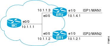
Perform this task at the master controller to configure a load balancing policy for traffic class flows over the border router exit links. In this example, range and exit utilization policies are given priority when OER chooses the best exit selection for traffic class flows. Best route selection for performance policies is disabled. The external Ethernet interfaces on border router 1 and border router 2—BR1 and BR2 in Figure 4—are both configured with a maximum utilization threshold of 70 percent and a range of utilization between the two exit links is set to 30 percent. After an external interface is configured for the border routers, OER automatically monitors the utilization of external links on a border router every 5 minutes. The utilization is reported back to the master controller and, if the utilization exceeds 70 percent, OER selects another exit link for traffic class flows on that link. To complete the load balancing, the utilization range between the two exit links must not be greater than 30 percent, otherwise OER will move some of the traffic classes from one exit link to another to balance the traffic load between the two exit links.
Figure 4 Network diagram for OER Exit Link Load Balancing
Traffic can also be load balanced over entrance links, for more details see the "Using OER to Control Traffic Classes and Verify the Network Performance" module.
SUMMARY STEPS
1.
2.
3.
4.
5.
6.
7.
8.
9.
10.
11.
12.
13.
14.
15.
16.
17.
DETAILED STEPS
Step 1
enable
Example:Router> enable
Enables privileged EXEC mode.
•
Step 2
configure terminal
Example:Router# configure terminal
Enters global configuration mode.
Step 3
oer master
Example:Router(config)# oer master
Enters OER master controller configuration mode to configure a router as a master controller and to configure global operations and policies.
Step 4
max-range-utilization percent maximum
Example:Router(config-oer-mc)# max-range-utilization percent 30
Sets the maximum utilization range for all OER-managed exit link.s.
•
•
Step 5
mode select-exit {best | good}
Example:Router(config-oer-mc)# mode select-exit best
Creates a set clause entry to configure exit selection settings.
•
•
Note
Step 6
resolve range priority value
Example:Router(config-oer-mc)# resolve range priority 1
Sets policy priority or resolves policy conflicts.
•
•
•
•
Note
Step 7
resolve utilization priority value variance percentage
Example:Router(config-oer-mc)# resolve utilization priority 2 variance 25
Sets policy priority or resolves policy conflicts.
•
•
•
•
•
Note
Step 8
no resolve delay
Example:Router(config-oer-mc)# no resolve delay
Disables any priority for delay performance policies.
Note
Step 9
no resolve loss
Example:Router(config-oer-mc)# no resolve loss
Disables any priority for loss performance policies.
Note
Step 10
border ip-address [key-chain key-chain-name]
Example:Router(config-oer-mc)# border 10.1.1.2 key-chain border1_OER
Enters OER-managed border router configuration mode to establish communication with a border router.
•
•
•
Note
Step 11
interface type number external
Example:Router(config-oer-mc-br)# interface Ethernet 1/0 external
Configures a border router interface as an OER-managed external interface.
•
•
TipNote
Step 12
max-xmit-utilization {absolute kbps | percentage value}
Example:Router(config-oer-mc-br-if)# max-xmit-utilization percentage 70
Configures the maximum utilization on a single OER managed exit link.
•
•
Step 13
exit
Example:Router(config-oer-mc-br-if)# exit
Exits OER-managed border exit interface configuration mode and returns to OER-managed border router configuration mode.
Step 14
exit
Example:Router(config-oer-mc-br)# exit
Exits OER-managed border router configuration mode and returns to OER master controller configuration mode.
Step 15
Repeat Step 10 through Step 14 with appropriate changes to set a utilization threshold for each external link.
—
Step 16
keepalive timer
Example:Router(config-oer-mc)# keepalive 10
(Optional) Configures the length of time that an OER master controller will maintain connectivity with an OER border router after no keepalive packets have been received.
•
Step 17
end
Example:Router(config-oer-mc-learn)# end
Exits OER Top Talker and Top Delay learning configuration mode and returns to privileged EXEC mode.
Implementing Performance Routing Link Groups
Perform this task on a master controller to set up some performance routing link groups by identifying an exit link on a border router as a member of a link group, and to create an OER map to specify link groups for traffic classes defined in an OER policy. In this task, a link group is set up for video traffic and a set of high bandwidth exit links are identified as members of the video link group which is identified as a primary link group. A fallback link group is also specified.
An OER policy is created using an OER map where the primary and fall link groups are specified for traffic classes matching the OER map criteria. OER probes both the primary and fallback group links and selects the best link in the primary link group for the traffic class specified in this task. If none of the primary links are within policy, OER selects the bast link from the fallback group. For more details about link groups, see the "Performance Routing Link Grouping" section.
Prerequisites
This task requires the master controller and border routers to be running Cisco IOS Release 12.4(15)T, or later release.
SUMMARY STEPS
1.
2.
3.
4.
5.
6.
7.
8.
9.
10.
11.
12.
13.
14.
15.
16.
17.
18.
19.
DETAILED STEPS
Step 1
enable
Example:Router> enable
Enables privileged EXEC mode.
•
Step 2
configure terminal
Example:Router# configure terminal
Enters global configuration mode.
Step 3
oer master
Example:Router(config)# oer master
Enters OER master controller configuration mode to configure a router as a master controller.
•
Note
Step 4
border ip-address [key-chain key-chain-name]
Example:Router(config-oer-mc)# border 192.168.1.2 key-chain border1_OER
Enters OER-managed border router configuration mode to establish communication with a border router.
•
•
•
Note
Step 5
interface type number external
Example:Router(config-oer-mc-br)# interface Serial 2/0 external
Configures a border router interface as an OER-managed external interface.
•
•
TipNote
Step 6
link-group link-group-name [link-group-name [link-group-name]]
Example:Router(config-oer-mc-br-if)# link-group VIDEO
Configures an OER border router exit interface as a member of a link group.
•
•
•
Note
Step 7
exit
Example:Router(config-oer-mc-br-if)# exit
Exits OER-managed border exit interface configuration mode and returns to OER-managed border router configuration mode.
Step 8
Repeat Step 5 through Step 7 with appropriate changes to set up link groups for all the external interface.
—
Step 9
interface type number internal
Example:Router(config-oer-mc-br)# interface FastEthernet 0/1 internal
Configures a border router interface as an OER controlled internal interface.
•
•
Note
Step 10
exit
Example:Router(config-oer-mc-br)# exit
Exits OER-managed border configuration mode and returns to global configuration mode.
Step 11
ip access-list {standard | extended} access-list-name
Example:Router(config)# ip access-list extended ACCESS_VIDEO
Defines an IP access list by name and enters extended named access list configuration mode.
•
•
Step 12
[sequence-number] permit udp source source-wildcard [operator [port]] destination destination-wildcard [operator [port]] [dscp dscp-value]
Example:Router(config-ext-nacl)# permit tcp any any 500
Sets conditions to allow a packet to pass a named IP access list.
•
Note
Step 13
Repeat Step 12 for more access list entries, as required.
—
Step 14
exit
Example:Router(config-ext-nacl)# exit
(Optional) Exits extended named access list configuration mode and returns to global configuration mode.
Step 15
oer-map map-name sequence-number
Example:Router(config)# oer-map VIDEO_MAP 10
Enters OER map configuration mode to configure an OER map.
•
•
•
Step 16
match traffic-class access-list access-list-name
Example:Router(config-oer-map)# traffic-class access-list ACCESS_VIDEO
Manually configures an access list as match criteria used to create traffic classes using an OER map.
•
•
Step 17
set link-group link-group-name [fallback link-group-name]
Example:Router(config-oer-map)# set link-group video fallback voice
Specifies a link group for traffic classes defined in an OER map to create an OER policy.
•
•
•
Step 18
end
Example:Router(config-oer-map)# end
(Optional) Exits OER map configuration mode and returns to privileged EXEC mode.
Step 19
show oer master link-group [link-group-name]
Example:Router# show oer master link-group
Displays information about configured OER link groups.
•
•
•
Examples
The example output from the show oer master link-group command displays information about performance routing link groups configured using OER. In this example, the VIDEO link group is shown with other configured link groups.
Router# show oer master link-grouplink group videoBorder Interface Exit id192.168.1.2 Serial2/0 1link group voiceBorder Interface Exit id192.168.1.2 Serial2/0 1192.168.1.2 Serial3/0 2192.168.3.2 Serial4/0 4link group dataBorder Interface Exit id192.168.3.2 Serial3/0 3Configuring OER Cost-Based Policies
Perform this task to configure cost-based optimization. Cost-based optimization is configured on a master controller using the cost-minimization command in OER border exit interface configuration mode (under the external interface configuration). Cost-based optimization supports tiered and fixed billing methods.
Prerequisites
This task requires the master controller and border routers to be running Cisco IOS Release 12.3(14)T, 12.2(33)SRB, or later releases.
SUMMARY STEPS
1.
2.
3.
4.
5.
6.
7.
8.
DETAILED STEPS
Configuring OER Network Security Policies
Perform one of the following two optional tasks to help prevent and mitigate attacks on your network. The first task uses the black hole routing technique, and the second task uses the sinkhole routing technique.
•
•
Configuring Black Hole Routing Using an OER Map
Perform this task to configure an OER map to filter packets to be forwarded to a null interface, meaning that the packets are discarded in a "black hole." The prefix list is configured after an IP prefix is identified as the source of the attack on the network. Some protocols such as BGP allow the redistribution of back hole routes, but other protocols do not.
Prerequisites
This task requires the master controller and border routers to be running Cisco IOS Release 12.4(9)T, 12.2(33)SRB, or later releases.
SUMMARY STEPS
1.
2.
3.
4.
5.
6.
7.
DETAILED STEPS
Configuring Sinkhole Routing Using an OER Map
Perform this task to configure an OER map to filter packets to be forwarded to a next hop. The next hop is a router where the packets can be stored, analyzed, or discarded (the sinkhole analogy). The prefix list is configured after an IP prefix is identified as the source of an attack on the network.
Prerequisites
This task requires the master controller and border routers to be running Cisco IOS Release 12.4(9)T, 12.2(33)SRB, or later releases.
SUMMARY STEPS
1.
2.
3.
4.
5.
6.
7.
DETAILED STEPS
Configuring OER Voice Traffic Optimization Using Active Probes
Support for optimizing voice traffic using OER was introduced in 12.4(6)T. Configuring OER to optimize voice traffic using active probes involves several decisions and subsequent branching tasks. The first step is to identify the traffic to be optimized and decide whether to use a prefix list or an access list. Use a prefix list to identify all traffic, including voice traffic, with a specific set of destination prefixes. Use an access list to identify only voice traffic with a specific destination prefix and carried over a specific protocol.
The second step in optimizing voice traffic is to configure active probing using the active-probe or set active-probe command to specify the type of active probe to be used. In Cisco IOS Release 12.4(6)T, 12.2(33)SRB, the ability to set a forced target assignment for the active probe was introduced.
The final step in optimizing voice traffic is to configure an OER policy to set the performance metrics that you want OER to apply to the identified traffic.
Perform one of the first two optional tasks, depending on whether you want to use a prefix list or an access list to identify the traffic to be optimized. The third task can be used with traffic identified using an access list, and it also demonstrates how to use a forced target assignment. For an example configuration that can be used with traffic identified using a prefix list, see the "Optimizing Only Voice Traffic Using Active Probes" section.
•
•
•
Identifying Traffic for OER Using a Prefix List
Before traffic can be measured using OER, it must be identified. Perform this task to use a prefix list to identify the traffic that OER will probe.
SUMMARY STEPS
1.
2.
3.
4.
DETAILED STEPS
Identifying Voice Traffic to Optimize Using an Access List
Perform this task to use an access list to identify the voice traffic. Before voice traffic can be optimized, it must be identified. Voice traffic that has to be optimized must be configured because OER does not "learn" about voice traffic on IP networks during an OER learn phase.
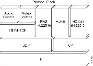
IP Protocol Stack for Voice
Voice traffic uses a variety of protocols and streams on the underlying IP network. Figure 5 is a representation of the protocol options available for carrying voice traffic over IP. Most signaling traffic for voice is carried over TCP. Most voice calls are carried over User Datagram Protocol (UDP) and Real-Time Protocol (RTP). You can configure your voice devices to use a specific range of destination port numbers over UDP to carry voice call traffic.
Figure 5 Protocol Stack Options Available for Voice Traffic
Prerequisites
This task requires the master controller and border routers to be running Cisco IOS Release 12.4(6)T, 12.2(33)SRB, or later release.
SUMMARY STEPS
1.
2.
3.
4.
5.
DETAILED STEPS
Step 1
enable
Example:Router> enable
Enables privileged EXEC mode.
•
Step 2
configure terminal
Example:Router# configure terminal
Enters global configuration mode.
Step 3
ip access-list {standard | extended} access-list-name
Example:Router(config)# ip access-list extended VOICE_ACCESS_LIST
Defines an IP access list by name.
•
•
Step 4
[sequence-number] permit udp source source-wildcard [operator [port]] destination destination-wildcard [operator [port]]
Example:Router(config-ext-nacl)# permit udp any range 16384 32767 10.20.20.0 0.0.0.15 range 16384 32767
Sets conditions to allow a packet to pass a named IP access list.
•
•
Step 5
end
Example:Router(config-ext-nacl)# end
(Optional) Exits extended access list configuration mode and returns to privileged EXEC mode.
Configuring OER Voice Probes with a Target Assignment
After identifying the traffic (in this example, voice traffic identified using an access list) to be optimized, perform this task to configure the OER jitter probes and assign the results of the jitter probes to optimize the identified traffic. In this task, the OER active voice probes are assigned a forced target for OER instead of the usual longest match assigned target. Before configuring the OER jitter probe on the source device, the IP SLAs Responder must be enabled on the target device (the operational target). The IP SLAs Responder is available only on Cisco IOS software-based devices. Start this task at the network device that runs the IP SLAs Responder.
Note
Note
Prerequisites
•
•
SUMMARY STEPS
1.
2.
3.
4.
5.
6.
7.
8.
9.
10.
11.
12.
13.
14.
15.
16.
17.
18.
19.
20.
21.
22.
DETAILED STEPS
Step 1
enable
Example:Router> enable
Enables privileged EXEC mode.
•
Step 2
configure terminal
Example:Router# configure terminal
Enters global configuration mode.
Step 3
ip sla monitor responder
Example:Router(config)# ip sla monitor responder
Enables the IP SLAs Responder.
Step 4
exit
Example:Router(config)# exit
Exits global configuration mode and returns to privileged EXEC mode.
Step 5
Move to the network device that is the OER master controller.
—
Step 6
enable
Example:Router> enable
Enables privileged EXEC mode.
•
Step 7
configure terminal
Example:Router# configure terminal
Enters global configuration mode.
Step 8
oer-map map-name sequence-number
Example:Router(config)# oer-map TARGET_MAP 10
Enters OER map configuration mode to configure an OER map to apply policies to selected IP prefixes.
•
•
•
Step 9
match ip address {access-list access-list-name | prefix-list prefix-list-name}
Example:Router(config-oer-map)# match ip address access-list VOICE_ACCESS_LIST
References an extended IP access list or IP prefix as match criteria in an OER map.
•
•
Step 10
set active-probe probe-type ip-address [target-port number] [codec codec-name]
Example:Router(config-oer-map)# set active-probe jitter 10.20.22.1 target-port 2000 codec g729a
Creates a set clause entry to assign a target prefix for an active probe.
•
•
•
•
•
Step 11
set probe frequency seconds
Example:Router(config-oer-map)# set probe frequency 10
Creates a set clause entry to set the frequency of the OER active probe.
•
•
Step 12
set jitter threshold maximum
Example:Router(config-oer-map)# set jitter threshold 20
Creates a set clause entry to configure the jitter threshold value.
•
•
Step 13
set mos {threshold minimum percent percent}
Example:Router(config-oer-map)# set mos threshold 4.0 percent 30
Creates a set clause entry to configure the MOS threshold and percentage values used to decide whether an alternate exit is be selected.
•
•
•
•
Step 14
set resolve {cost priority value | delay priority value variance percentage | jitter priority value variance percentage | loss priority value variance percentage | mos priority value variance percentage | range priority value | utilization priority value variance percentage}
Example:Router(config-oer-map)# set resolve jitter priority 1 variance 10
Creates a set clause entry to configure policy priority or resolve policy conflicts.
•
•
•
•
•
•
Step 15
set resolve mos priority value variance percentage
Example:Router(config-oer-map)# set resolve mos priority 2 variance 15
Creates a set clause entry to configure policy priority or resolve policy conflicts.
•
Note
Step 16
set delay {relative percentage | threshold maximum}
Example:Router(config-oer-map)# set delay threshold 100
Creates a set clause entry to configure the delay threshold.
•
•
•
•
Step 17
exit
Example:Router(config-oer-map)# exit
Exits OER map configuration mode and returns to global configuration mode.
Step 18
oer master
Example:Router(config)# oer master
Enters OER master controller configuration mode to configure a router as a master controller.
•
Note
Step 19
policy-rules map-name
Example:Router(config-oer-mc)# policy-rules TARGET_MAP
Applies a configuration from an OER map to a master controller configuration in OER master controller configuration mode.
•
•
Step 20
end
Example:Router(config-oer-mc)# end
Exits OER master controller configuration mode and enters privileged EXEC mode.
Step 21
show oer master active-probes [appl | forced]
Example:Router# show oer master active-probes forced
Displays connection and status information about active probes on an OER master controller.
•
•
•
•
Step 22
show oer master policy [sequence-number | policy-name | default]
Example:Router# show oer master policy TARGET_MAP
Displays policy settings on an OER master controller.
•
•
•
•
•
Examples
This example shows output from the show oer master active-probes forced command. The output is filtered to display only connection and status information about the active probes generated for voice traffic configured with a forced target assignment.
Router# show oer master active-probes forcedOER Master Controller active-probesBorder = Border Router running this ProbePolicy = Forced target is configure under this policyType = Probe TypeTarget = Target AddressTPort = Target PortN - Not applicableThe following Forced Probes are running:Border State Policy Type Target TPort10.20.20.2 ACTIVE 40 jitter 10.20.22.1 305010.20.21.3 ACTIVE 40 jitter 10.20.22.4 3050What to do Next
For further configuration examples of OER voice traffic optimization, see the "Configuring OER Voice Traffic Optimization Using Active Probes: Examples" section.
Configuration Examples for Configuring and Applying OER Policies
The following examples in this section show various OER policy configurations:
•
•
•
•
•
•
•
•
•
•
•
•
Configuring and Applying an OER Policy to Learned Traffic Classes: Example
The following example uses learned traffic classes and overwrites many of the default policy settings and configures the master controller to move traffic classes to the best available exit link when any of the configured or default policy settings exceed their thresholds:
enableconfigure terminaloer masterbackoff 200 2000 200delay threshold 2000holddown 400loss threshold 1500periodic 180unreachable threshold 1000mode select-exit bestendConfiguring and Applying an OER Policy to Configured Traffic Classes: Example
The following example uses traffic classes filtered by a prefix list and an access list and overwrites some of the default policy settings. The policies are configured using two OER maps that apply to different traffic classes that represent voice traffic. The master controller is configured to move traffic classes to the first in-policy exit link when any of the configured or default policy settings exceed their thresholds. To run this task, both the master controller and border routers must be running Cisco IOS Release 12.4(9)T, 12.2(33)SRB, or later releases.
enableconfigure terminalip prefix-list CONFIG_TRAFFIC_CLASS seq 10 permit 10.1.5.0/24ip access-list extended VOICE_TRAFFIC_CLASSpermit udp any range 16384 32767 10.1.5.0 0.0.0.15 range 16384 32767 dscp efexitoer-map CONFIG_MAP 10match ip address prefix-list CONFIG_TRAFFIC_CLASSset backoff 100 1000 100set delay threshold 1000set loss relative 25set periodic 360set unreachable relative 20exitoer-map VOICE_MAP 10match ip address access-list VOICE_TRAFFIC_CLASSset active-probe jitter 10.1.5.1 target-port 2000 codec g729aset probe-frequency 20set jitter threshold 30set mos threshold 4.0 percent 25set mode select-exit goodendPreventing OER Optimization of Learned Prefixes: Example
The following example shows how to configure OER to prevent specified prefixes being optimized. In this example, an IP prefix list is created with two entries for different prefixes that are not to be optimized. An OER map is configured with two entries in a sequence that will prevent OER from optimizing the prefixes specified in the prefix list, although the prefixes may be learned. If the sequence numbers of the OER map entries are reversed, OER will learn and attempt to optimize the prefixes.
enableconfigure terminalip prefix-list DENY_PREFIX deny 172.17.10.0/24ip prefix-list DENY_PREFIX deny 172.19.10.0/24oer-map DENY_PREFIX_MAP 10match ip address prefix-list DENY_PREFIXexitoer-map DENY_PREFIX_MAP 20match oer learn throughputendConfiguring and Applying an OER Policy to Learned Inside Prefixes: Example
The following example shows how to apply an OER policy to learned inside prefixes:
enableconfigure terminaloer-map INSIDE_LEARN 10match oer learn insideset delay threshold 2000set loss relative 20set unreachable relative 90endConfiguring and Applying an OER Policy to Configured Inside Prefixes: Example
The following example shows how to create an OER map named INSIDE_CONFIGURE and apply an OER policy to manually configured inside prefixes:
enableconfigure terminaloer-map INSIDE_CONFIGURE 10match ip address prefix-list INSIDE_PREFIXES insideset delay threshold 2000set loss relative 20set unreachable relative 80endConfiguring Policy Rules for OER Maps: Example
The following example shows how to configure the policy-rules command to apply the OER map configuration named BLUE under OER master controller mode:
enableconfigure terminaloer-map BLUE 10match oer learn delayset loss relative 90exitoer masterpolicy-rules BLUEexitConfiguring Multiple OER Policy Conflict Resolution: Example
The following example configures an OER resolve policy that sets delay to the highest priority, followed by loss, and then utilization. The delay policy is configured to allow a 20 percent variance, the loss policy is configured to allow a 30 percent variance, and the utilization policy is configured to allow a 10 percent variance.
enableconfigure terminaloer masterresolve delay priority 1 variance 20resolve loss priority 2 variance 30resolve utilization priority 3 variance 10endConfiguring an Exit Link Load Balancing OER Policy: Example
The following example configures an OER load balancing policy for traffic class flows over the border router exit links. This example task is performed at the master controller and configures an exit link utilization range and an exit link utilization threshold with policy priorities set for utilization and range policies. Performance policies, delay and loss, are disabled. OER uses both the utilization and range thresholds to load balance the traffic flow over the exit links.
enableconfigure terminaloer mastermax-range-utilization percentage 25mode select-exit bestresolve range priority 1resolve utilization priority 2 variance 15no resolve delayno resolve lossborder 10.1.4.1interface Ethernet 1/0 externalmax-xmit-utilization absolute 10000exitexitborder 10.1.2.1interface Ethernet 1/0 externalmax-xmit-utilization absolute 10000endImplementing Performance Routing Link Groups: Example
The following example shows how to implement link groups. In this example, an OER map named VIDEO_MAP is created to configure OER to define a traffic class that matches an access list named ACCESS_VIDEO. The traffic class is configured to use a link group named VIDEO as the primary link group, and a fallback group named VOICE. The VIDEO link group may be a set of high bandwidth links that are preferred for video traffic.
enableconfigure terminalborder 10.1.4.1interface serial 2/0 externallink-group VIDEOexitinterface serial 3/0 externallink-group VOICEexitinterface Ethernet 1/0 internalexitip access-list extended ACCESS_VIDEOpermit tcp any 10.1.1.0 0.0.0.255 eq 500permit tcp any 172.17.1.0 0.0.255.255 eq 500permit tcp any 172.17.1.0 0.0.255.255 range 700 750permit tcp 192.168.1.1 0.0.0.0 10.1.2.0 0.0.0.255 eq 800 any any dscp efexitoer-map VIDEO_MAP 10match traffic-class access-list ACCESS_VIDEOset link-group VIDEO fallback VOICEendConfiguring OER Cost-Based Policies: Example
The following example shows how to configure cost-based optimization on a master controller. Cost optimization configuration is applied under the external interface configuration. In this example, a policy for a tiered billing cycle is configured that sets a tiered fee of 1000 at 100 percent utilization, a tiered fee of 900 at 90 percent utilization, and a tiered fee of 800 at 80 percent utilization. Calculation is configured separately for egress and ingress samples. The time interval between sampling is set to 10 minutes and these samples are configured to be rolled up every 60 minutes.
enableconfigure terminaloer masterborder 10.5.5.55 key-chain keyinterface Ethernet 0/0 externalcost-minimization nickname ISP1cost-minimization end day-of-month 30 180cost-minimization calc separatecost-minimization sampling 10 rollup 60cost-minimization tier 100 fee 1000cost-minimization tier 90 fee 900cost-minimization tier 80 fee 800exitConfiguring OER Network Security Policies: Examples
Black Hole Routing Example
The following example creates an OER map named BLACK_HOLE_MAP that matches traffic defined in the IP prefix list named PREFIX_BLACK_HOLE. The OER map filters packets to be forwarded to a null interface, meaning that the packets are discarded in a "black hole." The prefix list is configured after an IP prefix is identified as the source of the attack on the network.
enableconfigure terminalip prefix-list PREFIX_BLACK_HOLE seq 10 permit 10.1.5.0/24oer-map BLACK_HOLE_MAP 10match ip address prefix-list PREFIX_BLACK_HOLEset interface null0endSink Hole Routing Example
The following example creates an OER map named SINK_HOLE_MAP that matches traffic defined in the IP prefix list named PREFIX_SINK_HOLE. The OER map filters packets to be forwarded to a next hop. The next hop is a router where the packets can be stored, analyzed, or discarded (the sinkhole analogy). The prefix list is configured after an IP prefix is identified as the source of an attack on the network.
enableconfigure terminalip prefix-list PREFIX_SINK_HOLE seq 10 permit 10.1.5.0/24oer-map SINK_HOLE_MAP 10match ip address prefix-list PREFIX_SINK_HOLEset next-hop 10.1.1.3endConfiguring OER Voice Traffic Optimization Using Active Probes: Examples
Voice packets traveling through an IP network are no different from data packets. In the plain old telephone system (POTS), voice traffic travels over circuit-switched networks with predetermined paths and each phone call is given a dedicated connection for the duration of the call. Voice traffic using POTS has no resource contention issues, but voice traffic over an IP network has to contend with factors such as delay, jitter, and packet loss, which can affect the quality of the phone call.
The following examples show both how to use an access list to identify only voice traffic to be optimized by OER and to use a prefix list to identify traffic that includes voice traffic to be optimized by OER.
•
•
Optimizing Only Voice Traffic Using Active Probes
Figure 6 shows that voice traffic originating at the remote office and terminating at the headquarters has to be optimized to select the best path out of the remote office network. Degradation in voice (traffic) quality is less likely to be introduced within the network, so probing the edge of the network gives a measurement that is close to probing the final destination.
Figure 6 OER Network Topology Optimizing Voice Traffic Using Active Probes
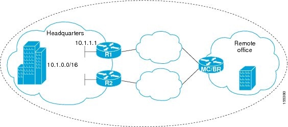
This configuration optimizes voice traffic to use the best performance path, whereas all other traffic destined to the same network—10.1.0.0/16—will follow the best path as indicated by a traditional routing protocol, for example BGP, that is configured on the device. As part of this optimization, OER will use policy based routing (PBR) to set the best exit link for voice traffic within a device.
The following configuration is performed on the edge router R1 in Figure 6 in the headquarters network to enable the IP SLAs Responder.
enableconfigure terminalip sla responderexitThe following configuration is performed on the edge router MC/BR (which is both an OER master controller and border router) in Figure 6 in the remote office network to optimize voice traffic using active probes.
enableconfigure terminalip access-list extended Voice_Traffic10 permit udp any 10.1.0.0 0.0.255.255 range 16384 32767exitoer-map Voice_MAP 10match ip address access-list Voice_Trafficset active-probe jitter 10.1.1.1 target-port 1025 codec g711alawset delay threshold 300set mos threshold 3.76 percent 30set jitter threshold 15set loss relative 5resolve mos priority 1resolve jitter priority 2resolve delay priority 3resolve loss priority 4Optimizing Traffic (Including Voice Traffic) Using Active Probes
Figure 7 shows that traffic originating in the headquarters network and destined for the remote office network has to be optimized based on voice traffic metrics. Voice traffic is one of the most important traffic classes that travel from the headquarters to the remote office network, so the voice traffic must be prioritized to be optimized. Degradation in voice packet quality is less likely to be introduced within the network, so probing the edge of the network gives a measurement that is close to probing the final destination.
Figure 7 OER Network Topology for Optimizing All Traffic Using Active Probes
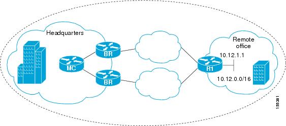
This configuration optimizes all traffic, including voice traffic, destined for the10.12.0.0/16 network. The OER optimization is based on the measurement of voice performance metrics with threshold values using active probes. As part of the optimization, OER will introduce a BGP or a static route into the headquarters network. For more details about BGP and static route optimization, see the Using OER to Control Traffic Classes and Verify the Route Control Changes module.
The following configuration is performed on router R1 in Figure 7 in the remote office network to enable the IP SLAs Responder.
enableconfigure terminalip sla responderexitThe following configuration is performed on one of the BR routers in Figure 7 in the headquarters network to optimize all traffic (including voice traffic) using active probes.
enableconfigure terminalip prefix-list All_Traffic_Prefix permit 10.12.0.0/16oer-map Traffic_MAP 10match ip address prefix-list All_Traffic_Prefixset active-probe jitter 10.12.1.1 target-port 1025 codec g711alaw! port 1025 for the target probe is an example.set delay threshold 300set mos threshold 3.76 percent 30set jitter threshold 15set loss relative 5resolve mos priority 1resolve jitter priority 2resolve delay priority 3resolve loss priority 4Where to Go Next
This module covered the OER apply policy phase and it has assumed that you started with the "Cisco IOS Optimized Edge Routing Overview" and the "Setting Up OER Network Components" module. The apply policy phase is the third phase in the OER performance loop. To learn more about the other OER phases, read through the other modules in the following list:
•
•
•
•
After you understand the various OER phases, review the OER solutions modules that are listed under "Related Documents" section.
Additional References
The following sections provide references related to configuring and applying OER policies.
Related Documents
Cisco OER technology overview
Concepts and configuration tasks required to set up OER network components.
OER solution module: voice traffic optimization using OER active probes.
OER solution module: configuring VPN IPsec/GRE tunnel interfaces as OER-managed exit links.
"Configuring VPN IPsec/GRE Tunnel Interfaces As OER-Managed Exit Links" module
Cisco OER commands: complete command syntax, command mode, command history, defaults, usage guidelines and examples
•
•
IP Routing Protocol commands
•
•
IP Routing Protocol configuration tasks
Cisco IOS IP Routing Protocols Configuration Guide, Release 12.4
Technical Assistance
Feature Information for Configuring and Applying OER Policies
Table 1 lists the features in this module and provides links to specific configuration information. Only features that were introduced or modified in Cisco IOS Release 12.3(8)T, 12.2(33)SRB, or a later release appear in the table.
For information on a feature in this technology that is not documented here, see the "Cisco IOS Optimized Edge Routing Feature Roadmap."
Not all commands may be available in your Cisco IOS software release. For release information about a specific command, see the command reference documentation.
Use Cisco Feature Navigator to find information about platform support and software image support. Cisco Feature Navigator enables you to determine which Cisco IOS and Catalyst OS software images support a specific software release, feature set, or platform. To access Cisco Feature Navigator, go to http://www.cisco.com/go/cfn. An account on Cisco.com is not required.
Note
Table 1 Feature Information for Configuring and Applying OER Policies
Optimized Edge Routing
12.3(8)T
12.2(33)SRBOER was introduced.
OER Support for Policy-Rules Configuration
12.3(11)T
12.2(33)SRBThe OER Support for Policy-Rules Configuration feature introduced the capability to select an OER map and apply the configuration under OER master controller configuration mode, providing an improved method to switch between predefined OER maps.
The following sections provide information about this feature:
•
•
•
The following commands were introduced or modified by this feature: policy-rules.
OER Support for Cost-Based Optimization
12.3(14)T
12.2(33)SRBThe OER Support for Cost-Based Optimization feature introduced the capability to configure exit link policies based monetary cost and the capability to configure traceroute probes to determine prefix characteristics on a hop-by-hop basis.
The following sections provide information about this feature:
•
•
The following commands were introduced or modified by this feature: cost-minimization, debug oer master cost-minimization, show oer master cost-minimization.
OER Voice Traffic Optimization
12.4(6)T
12.2(33)SRBThe OER Voice Traffic Optimization feature introduced support for outbound optimization of voice traffic based on the voice metrics, jitter and Mean Opinion Score (MOS). Jitter and MOS are important quantitative quality metrics for voice traffic and these voice metrics are measured using OER active probes.
The following sections provide information about this feature:
•
•
•
The following commands were introduced or modified by this feature: active-probe, jitter, mos, resolve, set jitter, set mos, set probe, set resolve, show oer master active-probes, show oer master policy, show oer master prefix.
OER BGP Inbound Optimization
12.4(9)T
12.2(33)SRBOER BGP inbound optimization supports best entrance selection for traffic that originates from prefixes outside an autonomous system destined for prefixes inside the autonomous system. External BGP (eBGP) advertisements from an autonomous system to an Internet service provider (ISP) can influence the entrance path for traffic entering the network. OER uses eBGP advertisements to manipulate the best entrance selection.
The following sections provide information about this feature:
•
•
•
•
The following commands were introduced or modified by this feature: clear oer master prefix, downgrade bgp, inside bgp, match ip address (OER), match oer learn, max range receive, maximum utilization receive, show oer master prefix.
OER DSCP Monitoring
12.4(9)T
12.2(33)SRBOER DSCP Monitoring introduced automatic learning of traffic classes based on protocol, port numbers, and DSCP value. Traffic classes can be defined by a combination of keys comprising of protocol, port numbers, and DSCP values, with the ability to filter out traffic that is not required, and the ability to aggregate the traffic in which you are interested. Information such as protocol, port number, and DSCP information is now sent to the master controller database in addition to the prefix information. The new functionality allows OER to both actively and passively monitor application traffic.
The following sections provide information about this feature:
•
•
•
The following commands were introduced or modified by this feature: show oer border passive applications, show oer border passive cache, show oer border passive learn, show oer master appl, traffic-class aggregation, traffic-class filter, and traffic-class keys.
Performance Routing - Link Groups
12.4(15)T
The Performance Routing - Link Groups feature introduces the ability to define a group of exit links as a preferred set of links, or a fallback set of links for OER to use when optimizing traffic classes specified in an OER policy.
The following sections provide information about this feature:
•
•
•
The following commands were introduced or modified by this feature: link-group, set link-group, and show oer master link-group.

Any Internet Protocol (IP) addresses used in this document are not intended to be actual addresses. Any examples, command display output, and figures included in the document are shown for illustrative purposes only. Any use of actual IP addresses in illustrative content is unintentional and coincidental.
© 2007 Cisco Systems, Inc. All rights reserved.
 Feedback