
Table Of Contents
Configuring Security on the GGSN
Overview of Security Support on the GGSN
Configuring AAA Security Globally
Configuring RADIUS Server Communication Globally
Configuring RADIUS Server Communication at the GGSN Configuration Level
Configuring Non-Transparent Access Mode
Specifying an AAA Server Group for All Access Points
Specifying an AAA Server Group for a Particular Access Point
Configuring AAA Accounting Services at an Access Point
Configuring Additional RADIUS Services
Configuring RADIUS Attributes in Access Requests to the RADIUS Server
Configuring the CHAP Challenge
Configuring the NAS-Identifier
Configuring the Charging ID in the Acct-Session-ID Attribute
Configuring the MSISDN in the User-Name Attribute
Configuring the Vendor-Specific Attribute in Access Requests to the RADIUS Server
Suppressing Attributes for RADIUS Authentication
Suppressing the MSISDN Number for RADIUS Authentication
Suppressing the 3GPP-IMSI VSA Sub-Attribute for RADIUS Authentication
Suppressing the 3GPP-GPRS-QoS Profile VSA Sub-Attribute for RADIUS Authentication
Suppressing the 3GPP-GPRS-SGSN-Address VSA Sub-Attribute for RADIUS Authentication
Obtaining DNS and NetBIOS Address Information from a RADIUS Server
Configuring the RADIUS Packet of Disconnect
Configuring the GGSN to Wait for a RADIUS Response
Configuring Access to a RADIUS Server Using VRF
Configuring a VRF-Aware Private RADIUS Server Group
Configuring Authentication, Authorization, and Accounting Using Named Method Lists
Configuring a VRF Routing Table
Configuring VRF on an Interface
Configuring VRF Under an Access Point for Access to the Private RADIUS Server
Configuring a Route to the RADIUS Server Using VRF
Configuring IPSec Network Security
IPSec Network Security on the Catalyst 6500 / Cisco 7600 Series Platform
Configuring IPSec Network Security on the Cisco 7200 Series Platform
Configuring Crypto Map Entries That Use IKE to Establish Security Associations
Securing the GGSN Mobile (Gn) Interface
Configuring Address Verification
Configuring Mobile-to-Mobile Traffic Redirection
AAA Security Configuration Example
RADIUS Server Global Configuration Example
RADIUS Server Group Configuration Example
RADIUS Response Message Configuration Example
IPSec Configuration using Crypto Map Entries
IPSec Configuration using VRF and IPSec Profile
Address Verification and Mobile-to-Mobile Traffic Redirection Example
Access to a Private RADIUS Server Using VRF Configuration Example
Configuring Security on the GGSN
This chapter describes how to configure security features on the gateway GPRS support node (GGSN), including Authentication, Authorization, and Accounting (AAA), RADIUS, and on the Cisco 7200 series router platform, IP Security (IPSec).
The security configuration procedures and examples in this publication (aside from those related to GGSN-specific implementation) describe the basic commands that you can use to implement the security services.
For more detailed information about AAA, RADIUS, and IPSec security services in the Cisco IOS software, refer to the Cisco IOS Security Configuration Guide and Cisco IOS Security Command Reference publications. For information about IPSec security services on Catalyst 6500 series switch / Cisco 7600 series internet router platform, see the IPSec VPN Acceleration Services Module Installation and Configuration Note.
For a complete description of the GGSN commands in this chapter, refer to the Cisco GGSN Release 5.2 Command Reference. To locate documentation of other commands that appear in this chapter, use the command reference master index or search online.
This chapter includes the following sections:
•
Overview of Security Support on the GGSN
•
•
•
•
•
•
Overview of Security Support on the GGSN
The GGSN supports many of the same levels of security that are available through the Cisco IOS software on the router, including the following types of security:
•
•
•
In addition, the GGSN software provides the ability to configure additional security features such as the following:
•
•
•
AAA and RADIUS support provides the security services to authenticate and authorize access by mobile users to the GGSN and its access point names (APNs). IPSec support allows you to secure your data between the GGSN and its associated peers.
In some cases, such as with AAA and IPSec support (on the Cisco 7200 series router platform), the GGSN works with the standard Cisco IOS software configuration without requiring configuration of any additional GGSN commands.

Note
In the case of RADIUS server configuration, the GGSN requires that you enable AAA security and establish RADIUS server communication globally on the router. From there, you can configure RADIUS security for all GGSN access points, or per access point, using new GGSN configuration commands.
Note
AAA Server Group Support
The Cisco GGSN supports authentication and accounting at APNs using AAA server groups. By using AAA server groups, you gain the following benefits:
•
•
•
For GPRS tunneling protocol (GTP)-PPP termination and GTP-PPP regeneration on the GGSN, transparent access mode is used to allow PPP to perform the appropriate AAA functions; however, you can still configure AAA server groups to specify the corresponding server groups for AAA support.
The GGSN supports the implementation of AAA server groups at both the global and access-point configuration levels. You can minimize your configuration by specifying the configuration that you want to support across most APNs, at the global configuration level. Then, at the access-point configuration level, you can selectively modify the services and server groups that you want to support at a particular APN. Therefore, you can override the AAA server global configuration at the APN configuration level.
To configure a default AAA server group to be used for all APNs on the GGSN, use the gprs default aaa-group global configuration command. To specify a different AAA server group to be used at a particular APN for authentication or accounting, use the aaa-group access-point configuration command.
If authentication is enabled on the APN, then the GGSN first looks for an authentication server group at the APN. If an authentication server group is not found at the APN, then the GGSN looks for a globally configured, General Packet Radio Service/Universal Mobile Telecommunication System (GPRS/UMTS) default authentication server group.
If accounting is enabled on the APN, then the GGSN looks for an accounting server group at the APN or globally in the following order:
•
•
•
•
To complete the configuration, you also must specify the following configuration elements on the GGSN:
•
•
•
–
You can disable accounting services at the APN by using the aaa-accounting disable command.
–
•
Note
Configuring AAA Security Globally
Authentication, authorization, and accounting (AAA) network security services provide the primary framework through which you set up access control on your GGSN. This section provides information about the basic commands used to implement AAA security on a Cisco router.
To enable AAA and configure authentication and authorization, use the following commands, beginning in global configuration mode:
For more information about configuring AAA, refer to the Cisco IOS Security Configuration Guide and Cisco IOS Security Command Reference publications.
Configuring RADIUS Server Communication Globally
This section describes how to configure a global RADIUS server host that the GGSN can use to authenticate and authorize users. You can configure additional RADIUS server communication at the GGSN global configuration level.
To globally configure RADIUS server communication on the router, use the following commands, beginning in global configuration mode:
For more information about configuring RADIUS security, refer to the Cisco IOS Security Configuration Guide and Cisco IOS Security Command Reference publications. For an example, see the "RADIUS Server Global Configuration Example" section.
Note
Configuring RADIUS Server Communication at the GGSN Configuration Level
To complete the security configuration for the GGSN, you must configure non-transparent access for each access point. When you configure security at the GGSN global configuration level, you can also configure RADIUS server communication for all access points or for a specific access point.
Configuring RADIUS at the GGSN global configuration level includes the following tasks:
•
•
•
•
Configuring Non-Transparent Access Mode
To support RADIUS authentication on the GGSN, you must configure the GGSN access points for non-transparent access. You must configure non-transparent access for every access point at which you want to support RADIUS services. There is no way to globally specify the access mode.
Note
To configure non-transparent access for a GGSN access point, use the following commands, beginning in global configuration mode:
For more information about configuring GGSN access points, see the "Configuring Access Points on the GGSN" section.
Specifying an AAA Server Group for All Access Points
After you have configured RADIUS server communication at the global level, you can configure a default AAA server group to be used by all GGSN access points.
To specify a default AAA server group for all GGSN access points, use the following command in global configuration mode:
Specifying an AAA Server Group for a Particular Access Point
To override the default AAA server group configured for all access points, you can specify a different AAA server group for a particular access point. Or, if you choose not to configure a default AAA server group, you can specify an AAA server group at each access point.
To specify an AAA server group for a particular access point, use the following command in access-point configuration mode:
Configuring AAA Accounting Services at an Access Point
The Cisco GGSN has different defaults for enabling and disabling accounting services for transparent and non-transparent access points:
•
•
Therefore, if you have configured a transparent access APN and you want to provide accounting at that APN, you need to configure the aaa-accounting enable command at the APN.
However, for accounting to occur, you also must complete the configuration by specifying the following other configuration elements on the GGSN:
•
•
•
–
–
–
•
•
Note
To selectively disable accounting at specific APNs where you do not want that service, use the aaa-accounting disable access-point configuration command.
There is not a no form of this command.
Enabling and Disabling Accounting Services for an Access Point
The Cisco Systems GGSN has different defaults for enabling and disabling accounting services for transparent and non-transparent access points:
•
•
To selectively disable accounting at specific APNs where you do not want that service, use the aaa-accounting disable access-point configuration command.
Configuring Interim Accounting for an Access Point
Using the aaa-accounting interim access-point configuration command, you can configure the GGSN to send Interim-Update Accounting requests to the AAA server when a routing area update (resulting in an SGSN change) or quality of service (QoS) change has occurred for a Packet Data Protocol (PDP) context. These changes are conveyed to the GGSN by an Update PDP Context request.
Note
To configure accounting services at an access point, use the following command in access-point configuration mode:
Configuring Additional RADIUS Services
This section describes how to configure RADIUS security services that the GGSN can use to authenticate and authorize users.
This section includes the following tasks:
•
•
•
•
•
•
•
Configuring RADIUS Attributes in Access Requests to the RADIUS Server
You configure the how the GGSN sends RADIUS attributes in access requests to the RADIUS server. This section includes the following tasks:
•
•
•
•
Configuring the CHAP Challenge
To specify that the Challenge Handshake Authentication Protocol (CHAP) challenge always be included in the Challenge Attribute field (and not in the Authenticator field) in access requests to the RADIUS server, use the following command in global configuration mode:
Router(config)# gprs radius attribute chap-challenge
Specifies that the CHAP challenge is always included in the challenge attribute in a RADIUS request.
Note
Configuring the MSISDN IE
To specify that the first byte of the mobile station ISDN (MSISDN) information element (IE) is included in access requests to the RADIUS server, use the following command in global configuration mode:
Router(config)# gprs radius msisdn first-byte
Specifies that the first byte of the MSISDN IE is included in access requests.
Configuring the NAS-Identifier
You can configure the GGSN to send the network access server (NAS)-Identifier (RADIUS attribute 32) in access requests to a RADIUS server at a global or APN level. The APN-level configuration overrides the global-level configuration.
To specify that the NAS-Identifier be included in all access requests, use the following command in global configuration mode:
To disable this global configuration, use the no form of this command while in global configuration mode.
To specify that the NAS-Identifier be included in all access requests at an APN, use the following command in access point configuration mode:
To disable this APN configuration, use the no form of this command while in access point configuration mode.
Configuring the Charging ID in the Acct-Session-ID Attribute
To specify that the GGSN include the charging ID in the Acct-Session-ID (attribute 44) in accounting requests at an APN, use the following command in access-point configuration mode:
Router(config)# radius attribute acct-session-id charging-id
Specifies that the charging ID in the Acct-Session-ID (attribute 44) is included in accounting requests.
To disable this APN configuration, use the no form of this command while in access point configuration mode.
Configuring the MSISDN in the User-Name Attribute
To specify that the GGSN include the MSISDN in the User-Name attribute (attribute 1) in access requests at an APN, use the following command in access-point configuration mode:
Router(config)# radius attribute user-name msisdn
Specifies that the MSISDN is included in the User-Name (attribute 1) field in access requests.
To disable this APN configuration, use the no form of this command while in access point configuration mode.
Configuring the Vendor-Specific Attribute in Access Requests to the RADIUS Server
The Internet Engineering Task Force (IETF) draft standard specifies a method for communicating vendor-specific information to the RADIUS server by using the vendor-specific attribute (attribute 26). Vendor-specific attributes (VSAs) make a larger set of information available for communication by allowing vendors to support their own extended attributes not suitable for general use.
Table 10-1 lists and describes the Third Generation Partnership Project (3GPP) VSA sub-attributes that the GGSN can send in authentication and accounting requests to a RADIUS server.
To configure the GGSN to send and recognize VSAs as defined by RADIUS attribute 26, use the following command in global configuration mode:
Router(config)#radius-server vsa send [accounting | authentication]
(Optional) Enables the GGSN to send and recognized VSAs as defined by RADIUS IETF attribute 26.
For more information on configuring the use of vendor-specific attributes, refer to the Cisco IOS Security Configuration Guide and Cisco IOS Security Command Reference publications.
Suppressing Attributes for RADIUS Authentication
You can configure the GGSN to suppress certain attributes in its access requests to a RADIUS server. The following sections describe the attributes you can suppress and how to do so.
The following topics are included in this section:
•
•
•
•
Suppressing the MSISDN Number for RADIUS Authentication
Some countries have privacy laws that prohibit service providers from identifying the MSISDN number of mobile stations in authentication requests. Use the msisdn suppression command to specify a value that the GGSN sends instead of the MSISDN number in its authentication requests to a RADIUS server. If no value is configured, then no number is sent to the RADIUS server.
To use the msisdn suppression command, you must configure a RADIUS server either globally or at the access point and specify non-transparent access mode.
To specify that the GGSN override or suppress the MSISDN number in its access-requests sent to the RADIUS server, use the following command in access-point configuration mode:
Router(config-access-point)# msisdn suppression [value]
(Optional) Specifies that the GGSN overrides the MSISDN number with a preconfigured value in its access requests.
To disable this APN configuration, use the no form of this command while in access point configuration mode.
Suppressing the 3GPP-IMSI VSA Sub-Attribute for RADIUS Authentication
To configure the GGSN to suppress the Third Generation Partnership Project (3GPP) vendor-specific attribute (VSA) 3GPP-International Mobile Subscriber Identity (3GPP-IMSI) number in its authentication and accounting requests to a RADIUS server, use the radius attribute suppress imsi access point configuration command.
To configure the GGSN to suppress the 3GPP VSA 3GPP-IMSI number in its authentication and accounting requests to a RADIUS server, use the following command in access-point configuration mode:
To disable this APN configuration, use the no form of this command while in access point configuration mode.
Suppressing the 3GPP-GPRS-QoS Profile VSA Sub-Attribute for RADIUS Authentication
To configure the GGSN to suppress the 3GPP-GPRS-Qos Profile in its authentication and accounting requests to a RADIUS server, use the radius attribute suppress qos access point configuration command.
To configure the GGSN to suppress the 3GPP-GPRS-Qos Profile in its authentication and accounting requests to a RADIUS server, use the following command in access-point configuration mode:
Suppressing the 3GPP-GPRS-SGSN-Address VSA Sub-Attribute for RADIUS Authentication
To configure the GGSN to suppress the 3GPP-GPRS-SGSN-Address in its authentication and accounting requests to a RADIUS server, use the radius attribute suppress sgsn-address access point configuration command.
To specify that the GGSN suppress the 3GPP-GPRS-SGSN-Address in its authentication and accounting requests to a RADIUS server, use the following command in access-point configuration mode:
Router(config-access-point)# radius attribute suppress sgsn-address
(Optional) Specifies that the GGSN suppresses the 3GPP-GPRS-SGSN-Address in its requests.
Obtaining DNS and NetBIOS Address Information from a RADIUS Server
To obtain Domain Name System (DNS) address and Network Basic Input/Output System (NetBIOS) address information from a RADIUS server, issue the following command in global configuration mode:
Router(config)# radius-server vsa send [accounting | authentication]
(Optional) Enables the GGSN to send and recognize VSAs as defined by RADIUS IETF attribute 26.
Note
Configuring the RADIUS Packet of Disconnect
The RADIUS Packet of Disconnect (POD) feature is a method for terminating a user session after the session has been established. The POD is a RADIUS Disconnect-Req packet and is intended to be used in situations when an authenticating agent server wants to disconnect a user after a session has been accepted by the RADIUS access-accept packet. For example, in the case of pre-paid billing, a typical use of this feature would be for the pre-paid billing server to send a POD when the quota expires for a pre-paid user.
Upon receiving a POD, the GGSN performs the following actions:
•
•
•
Note
To enable POD support on the GGSN, use the following command in global configuration mode:
Configuring the GGSN to Wait for a RADIUS Response
Use the gtp response-message wait-accounting command to configure the GGSN to wait for a RADIUS accounting response from the RADIUS accounting server before sending a Create PDP Context response to the SGSN.
If the GGSN does not receive a response from the RADIUS accounting server when you have configured the gtp response-message wait-accounting command, it rejects the PDP context request.
When broadcast accounting is used (accounting requests are sent to multiple RADIUS servers), if a RADIUS server responds with an accounting response, the GGSN sends a create PDP context response and does not wait for the other RADIUS servers to respond.
The GGSN supports configuration of RADIUS response message waiting at both the global and access-point configuration levels. You can minimize your configuration by specifying the configuration that you want to support across most APNs, at the global configuration level. Then, at the access-point configuration level, you can selectively modify the behavior that you want to support at a particular APN. Therefore, at the APN configuration level, you can override the global configuration of RADIUS response message waiting.
To configure the GGSN to wait for a RADIUS accounting response as the default behavior for all APNs, use the gprs gtp response-message wait-accounting global configuration command. To disable this behavior for a particular APN, use the no gtp response-message wait-accounting access-point configuration command.
To verify whether RADIUS response message waiting is enabled or disabled at an APN, you can use the show gprs access-point command and observe the value reported in the wait_accounting output field.
To configure the GGSN to wait for a RADIUS accounting response globally, use the following command in global configuration mode:
To configure the GGSN to wait for a RADIUS accounting response for a particular access point, use the following command in access-point configuration mode:
Configuring Access to a RADIUS Server Using VRF
The Cisco IOS GGSN software supports access to a RADIUS server using VRF. This Cisco IOS software feature is called Per VRF AAA and using this feature, Internet service providers (ISPs) can partition AAA services based on VRF. This permits the GGSN to communicate directly with the customer RADIUS server associated with the customer Virtual Private Network (VPN) without having to go through a RADIUS proxy. Thus, ISPs can scale their VPN offerings more efficiently because they no longer need to proxy AAA to provide their customers the flexibility demanded.
To support this configuration, AAA must be VRF aware. ISPs must define multiple instances of the same operational parameters—such as AAA server groups, method lists, system accounting, and protocol-specific parameters—and secure the parameters to the VRF partitions.
Note
The Catalyst 6500 / Cisco 7600 Sup720 supports VRF.
If an AAA configuration, such as a method list, is uniquely defined many times, the specification of an AAA server that is based on IP addresses and port numbers might create an overlapping of private addresses between VRFs. Securing AAA method lists to a VRF can be accomplished from one or more of the following sources:
•
•
•
Note
When configuring the Per VRF feature, keep in mind the following:
•
•
•
Note
•
Note
This section describes configuring and establishing access to a private RADIUS server using VRF. For global RADIUS services, ensure that you have configured a globally located server.
To configure access to a RADIUS server using VRF, complete the following tasks:
•
•
•
•
•
•
•
Enabling AAA Globally
If AAA has not been enabled globally on the GGSN, you will need to enable it before configuring access to a private RADIUS server via VRF.
To enable AAA globally, use the following command in global configuration mode:
Configuring a VRF-Aware Private RADIUS Server Group
To configure private server operational parameters, use the following commands, beginning in global configuration mode:
Configuring Authentication, Authorization, and Accounting Using Named Method Lists
To configure AAA using named method lists, perform the following tasks, beginning in global configuration mode:
Configuring a VRF Routing Table
To configure a VRF routing table on the GGSN for access to the private RADIUS server, use the following commands, beginning in global configuration mode:
Configuring VRF on an Interface
To access the private RADIUS server, VRF must be configured on the interface to the server.
On the Cisco 7200 series router platform, this interface is physical. On the Catalyst 6500 series switch / Cisco 7600 series Internet router platform, this interface is a logical one (on which IEEE 802.1Q-encapsulation has been configured) to a Layer 3 routed VLAN configured on the Supervisor/MSFC2.
For more information about required VLANs on the Supervisor/MSFC2, see the "Catalyst 6500 / Cisco 7600 Series Platform Prerequisites" section.
For more information about configuring interfaces, refer to the Cisco IOS Interface Configuration Guide and the Cisco IOS Interface Command Reference.
Configuring Physical Interfaces
To configure a physical interface using Fast Ethernet over the interface, use the following commands, beginning in global configuration mode:
Step 1
Router(config)# interface type slot/port
Defines a physical interface on the GGSN, where type is fastethernet, and slot/port is the hardware slot and port on the interface.
Step 2
Router(config-if)# ip vrf forwarding vrf-name
Associates a VRF with an interface or subinterface.
Note
Note
Step 3
Router(config-if)# ip address ip-address mask [secondary]
Specifies an IP address for the interface, where:
•
•
•
Configuring 802.1Q-Encapsulated Subinterfaces
To configure a subinterface that supports IEEE 802.1Q encapsulation to the associated VLAN on the Supervisor/MSFC2, use the following commands, beginning in global configuration mode:
Configuring VRF Under an Access Point for Access to the Private RADIUS Server
After you have completed the prerequisite configuration tasks on the Cisco 7200 platform, you can configure access to a RADIUS server with a tunnel or without a tunnel.
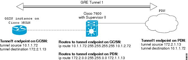
VRF is not supported on the Catalyst 6500 / Cisco 7600 Supervisor II / MSFC2; therefore, if using the Supervisor II, you must tunnel encapsulated VRF traffic through the Supervisor via a GRE tunnel between the GGSN to RADIUS server.
Note
Figure 10-1 is a logical view of a GRE tunnel configured between the VRF-aware GGSN and RADIUS server, which tunnels the encapsulated VRF traffic through the VRF-unaware Supervisor II / MSFC2.
Figure 10-1 GRE Tunnel Configuration from the GGSN to RADIUS Server through the Catalyst 6500 / Cisco 7600 Supervisor/MSFC2
The following sections describe the different methods you can use to configure access a RADIUS server:
•
•
Configuring Access to a RADIUS Server Without a Tunnel
On the Cisco 7200 platform, to configure access to the RADIUS server without a tunnel, you need to configure the vrf access point configuration command.
Note
To configure access to a RADIUS server in the GPRS access point list, use the following commands, beginning in global configuration mode:
Step 1
Router(config)# gprs access-point-list list-name
Specifies a name for a new access point list, or references the name of the existing access point list, and enters access-point list configuration mode.
Step 2
Router(config-ap-list)# access-point access-point-index
Specifies an index number for a new access point definition, or references an existing access point definition, and enters access point configuration mode.
Step 3
Router(config-access-point)# access-point-name apn-name
Specifies the network (or domain) name for a PDN that users can access from the GGSN at a defined access point.
Note
Step 4
Router(config-access-point)# aaa-group authentication server-group
Specifies a default AAA server group and assigns the type of AAA services to be supported by the server group for a particular access point on the GGSN, where:
•
•
Note
Step 5
Router(config-access-point)# access-mode non-transparent
Specifies for the GGSN to act as a proxy for authentication.
Step 6
Router(config-access-point)# ip-address-pool radius-client
Specifies for the RADIUS server to provide the IP address pool for the current access point.
Note
Step 7
Router(config-access-point)# vrf vrf-name
Configures VPN routing and forwarding at a GGSN access point, and associates the access point with a particular VRF instance.
Note
Step 8
Router(config-access-point)# exit
Exits access point configuration mode.
Configuring Access to a RADIUS Server With a Tunnel
If you have only a single interface to a RADIUS server from which you need to access one or more private RADIUS servers, or if you are configuring access to a RADIUS server via VRF on the Catalyst 6500 / Cisco 7600 platform, you can configure an IP tunnel to access those private servers. On the Catalyst 6500 / Cisco 7600 platform, you configure the tunnel to tunnel the VRF traffic through the Supervisor/MSFC2, which does not support VRF.
To configure access to the RADIUS server using a tunnel, perform the following tasks:
•
•
Configuring the Private RADIUS Server Access Point
To configure access to a private RADIUS server in the GPRS access point list, use the following commands, beginning in global configuration mode:
Configuring the IP Tunnel
When you configure a tunnel, you might consider using loopback interfaces as the tunnel endpoints instead of real interfaces because loopback interfaces are always up.
To configure an IP tunnel to a private network, use the following commands, beginning in global configuration mode:
Configuring a Route to the RADIUS Server Using VRF
Be sure a route exists between the VRF instance and the RADIUS server. You can verify connectivity by using the ping command from the VRF to the RADIUS server. To configure a route, you can use a static route or a routing protocol.
Configuring a Static Route Using VRF
To configure a static route using, use the following command, beginning in global configuration mode:
Verifying a Static Route Using VRF
To verify the static VRF route that you configured, use the show ip route vrf privileged EXEC command as shown in the following example:
GGSN# show ip route vrf vpn1 static172.16.0.0/16 is subnetted, 1 subnetsC 172.16.0.1 is directly connected, Ethernet5/1C 10.100.0.3/8 is directly connected, Virtual-Access5Configuring an OSPF Route Using VRF
To configure an OSPF route using VRF, use the following command, beginning in global configuration mode:
Configuring IPSec Network Security
In Cisco IOS Release 12.1(5)T and later, the GGSN software on the Cisco 7200 series router platform supports the IPSec for data authentication, confidentiality, encryption and integrity.
IPSec Network Security on the Catalyst 6500 / Cisco 7600 Series Platform
IPSec on the Catalyst 6500 series switch / Cisco 7600 series Internet router platform is performed on the IPSec VPN Acceleration Services module and requires no configuration on the GGSNs running on the Cisco MWAM.
For information about configuring IPSec on the Catalyst 6500 series switch / Cisco 7600 series Internet router platform, refer to the IPSEC VPN Acceleration Services Module Installation and Configuration Note.
Configuring IPSec Network Security on the Cisco 7200 Series Platform
On the Cisco 7200 series platform, IPSec data security can be implemented between the GGSN and another router on the PDN.
Note
Configuring IPSec network security includes the following tasks:
•
•
•
•
•
For more information about configuring IPSec, refer to the Cisco IOS Security Configuration Guide and Cisco IOS Security Command Reference publications.
For an example, see the "IPSec Configuration Examples" section.
Configuring an IKE Policy
You can create multiple Internet Key Exchange (IKE) policies, each with a different combination of parameter values. For each policy that you create, you assign a unique priority (1 through 10,000, with 1 being the highest priority).
You can configure multiple policies on each peer—but at least one of these policies must contain exactly the same encryption, hash, authentication, and Diffie-Hellman parameter values as one of the policies on the remote peer. For example, you can configure multiple policies on the GGSN to correlate with the policies for different PDNs.
To configure an IKE policy on the GGSN and corresponding PDN, use the following commands, beginning in global configuration mode:
For more information about IKE policy parameters, refer to the Cisco IOS Security Configuration Guide and Cisco IOS Security Command Reference publications.
Configuring Pre-Shared Keys
When you configure the pre-share authentication method for your IKE policy, you also must configure the pre-shared keys on the GGSN and remote peer, or PDN.
To configure pre-shared keys on the GGSN and corresponding PDN, use one of the following commands, beginning in global configuration mode:
Configuring Transform Sets
A transform set represents a certain combination of security protocols and algorithms. During the IPSec security association negotiation, the peers agree to use a particular transform set for protecting a particular data flow.
To configure a transform set on the GGSN and corresponding PDN, use the following commands, beginning in global configuration mode:
Configuring IPSec Profiles
Using an IPSec profile configuration is the recommended configuration for IPSec on VRF-aware generic routing encapsulation (GRE) tunnel interface between the GGSN and a PDN.
The IPSec profile shares most of the same commands with the crypto map configuration, but only a subset of the commands are valid in an IPSec profile. Only commands that pertain to an IPSec policy can be issued under an IPSec profile; you cannot specify the IPSec peer address or the access control list (ACL) to match the packets that are to be encrypted.
The following valid commands can be configured under an IPSec profile:
•
•
•
•
Note
To define the IPSecurity (IPSec) parameters that are to be used for IPSec encryption between the GGSN and PDN, use the following commands, beginning in global configuration mode:
To configure an IPSec profile on the GGSN and corresponding PDN, use the following commands, beginning in global configuration mode:
To delete an IPSec profile, use the no form of this command.
Configuring Crypto Map Entries That Use IKE to Establish Security Associations
When you use IKE to establish security associations, you can use a crypto map entry to specify a list of acceptable settings to be used during IPSec peer negotiation.
To configure crypto map entries on the GGSN and corresponding PDN, use the following commands, beginning in global configuration mode:
Securing the GGSN Mobile (Gn) Interface
The following features provide additional security for the GGSN mobile interface against attacks that can lead to illegal access to a network or even network downtime: address verification and mobile-to-mobile traffic redirection. The following tasks are necessary for configuring these features:
•
•
Configuring Address Verification
Use the security verify source access point configuration command to configure the GGSN to verify the source IP address of an upstream TPDU against the address previously assigned to an MS.
When the security verify source command is configured on an APN, the GGSN verifies the source address of a TPDU before GTP will accept and forward it. If the GGSN determines that the address differs from that previously assigned to the MS, it drops the TPDU and regards it as an illegal packet in its PDP context and APN. Configuring the security verify source access point configuration command protects the GGSN from faked user identities.
Use the security verify destination access point configuration command to have the GGSN verify the destination addresses of upstream TPDUs against global lists of PLMN addresses specified using the gprs plmn ip address command. If the GGSN determines that a destination address of a TPDU is within the range of a list of addresses, it drops the TPDU. If it determines that the TPDU contains a destination address that does not fall within the range of a list, it forwards the TPDU to its final destination.
Note
To configure address verification for a GGSN access point, use the following commands, beginning in access-point configuration mode:
Router(config-access-point)# security verify {source | destination}
(Optional) Specifies that the GGSN verify the source or destination address in TPDUs received from a Gn interface.
Note
Configuring Mobile-to-Mobile Traffic Redirection
Mobile-to-mobile traffic enters and exits through a Gn interface. Therefore, it is switched by the GGSN without ever going through a Gi interface on the network side. Because of this, firewalls deployed on the network side of a GGSN do not have an opportunity to verify this level of traffic.
Use the redirect intermobile ip access-point command to redirect mobile-to-mobile traffic to an external device (such as an external firewall) for verification.
Router(config-access-point)# redirect intermobile ip ip address
(Optional) Specifies that mobile-to-mobile traffic be redirected to an external device.
Note
Note
Redirecting All Traffic
The redirect all traffic feature enables you to do the following:
•
•
To redirect all traffic to a specific IP address, issue the following command while in access-point configuration mode:
Router(config-access-point)# redirect all ip ip address
Specifies that all traffic be redirected to an external device.
Configuration Examples
This section includes the following configuration examples for security on the GGSN:
•
•
•
•
•
AAA Security Configuration Example
The following example shows how to enable AAA security globally on the router and how to specify global RADIUS authentication and authorization:
! Enables AAA globallyaaa new-model!! Creates a local authentication list for use on! serial interfaces running PPP using RADIUS!aaa authentication ppp foo group foo!! Enables authorization and creates an authorization! method list for all network-related service requests! and enables authorization using a RADIUS server!aaa authorization network network foo group fooFor more information about configuring AAA, refer to the Cisco IOS Security Configuration Guide and Cisco IOS Security Command Reference publications.
RADIUS Server Global Configuration Example
The following example shows how to globally configure RADIUS server communication on the router:
! Specifies a global RADIUS server host at IP address 10.100.0.2! Port 1645 is destination port for authentication requests! Port 1646 is the destination port for accounting requests! Specifies the key "foo" for this radius host only!radius-server host 10.100.0.2 auth-port 1645 acct-port 1646 key foo!! Sets the authentication and encryption key to mykey for all! RADIUS communications between the router and the RADIUS daemon!radius-server key mykey
Note
For more information about configuring RADIUS security, refer to the Cisco IOS Security Configuration Guide and Cisco IOS Security Command Reference publications.
RADIUS Server Group Configuration Example
The following configuration example defines four AAA server groups on the GGSN: foo, foo1, foo2, and foo3, shown by the aaa group server commands.
Using the gprs default aaa-group command, two of these server groups are globally defined as default server groups: foo2 for authentication, and foo3 for accounting.
At access-point 1, which is enabled for authentication, the default global authentication server group of foo2 is overridden and the server group named foo is designated to provide authentication services on the APN. Notice that accounting services are not explicitly configured at that access point, but are automatically enabled because authentication is enabled. Because there is a globally defined accounting server-group defined, the server named foo3 will be used for accounting services.
At access-point 4, which is enabled for accounting using the aaa-accounting enable command, the default accounting server group of foo3 is overridden and the server group named foo1 is designated to provide accounting services on the APN.
Access-point 5 does not support any AAA services because it is configured for transparent access mode.
! Enables AAA globally!aaa new-model!! Defines AAA server groups!aaa group server radius fooserver 10.2.3.4 auth-port 1645 acct-port 1646server 10.6.7.8 auth-port 1645 acct-port 1646aaa group server radius foo1server 10.10.0.1 auth-port 1645 acct-port 1646aaa group server radius foo2server 10.2.3.4 auth-port 1645 acct-port 1646server 10.10.0.1 auth-port 1645 acct-port 1646aaa group server foo3server 10.6.7.8 auth-port 1645 acct-port 1646server 10.10.0.1 auth-port 1645 acct-port 1646!! Configures AAA authentication! and authorization!aaa authentication ppp foo group fooaaa authentication ppp foo2 group foo2aaa authorization network foo group fooaaa accounting network foo start-stop group fooaaa accounting network foo1 start-stop group foo1aaa accounting network foo2 start-stop group foo2aaa accounting network foo3 start-stop group foo3!gprs access-point-list gprsaccess-point 1access-mode non-transparentaccess-point-name www.pdn1.com!! Specifies a RADIUS server group! for use by the GGSN to authenticate! mobile users at this access point!aaa-group authentication foo!access-point 4access-point-name www.pdn2.com!! Enables AAA accounting services!aaa-accounting enable!! Specifies a RADIUS server group! for use by the GGSN for accounting! services at this access pointaaa-group accounting foo1!access-point 5access-point-name www.pdn3.com!! Configures default AAA server! groups for the GGSN for authentication! and accounting services!gprs default aaa-group authentication foo2gprs default aaa-group accounting foo3!! Configures global RADIUS server hosts! and specifies destination ports for! authentication and accounting requests!radius-server host 10.2.3.4 auth-port 1645 acct-port 1646 non-standardradius-server host 10.6.7.8 auth-port 1645 acct-port 1646 non-standardradius-server host 10.10.0.1 auth-port 1645 acct-port 1646 non-standardradius-server key ggsntel
Note
RADIUS Response Message Configuration Example
The following example globally configures the GGSN to wait for a RADIUS accounting response from the RADIUS server before sending a Create PDP Context response to the SGSN. The GGSN waits for a response for PDP context requests received across all access points, except access-point 1. RADIUS response message waiting has been overridden at access-point 1 by using the no gtp response-message wait-accounting command:
! Enables AAA globally!aaa new-model!! Defines AAA server group!aaa group server radius fooserver 10.2.3.4 auth-port 1645 acct-port 1646server 10.6.7.8 auth-port 1645 acct-port 1646!! Configures AAA authentication! and authorization!aaa authentication ppp foo group fooaaa authorization network foo group fooaaa accounting network foo start-stop group foo!gprs access-point-list gprsaccess-point 1access-mode non-transparentaccess-point-name www.pdn1.comaaa-group authentication foo!! Disables waiting for RADIUS response! message at APN 1!no gtp response-message wait-accountingexitaccess-point 2access-mode non-transparentaccess-point-name www.pdn2.comaaa-group authentication foo!! Enables waiting for RADIUS response! messages across all APNs (except APN 1)!gprs gtp response-message wait-accounting!! Configures global RADIUS server hosts! and specifies destination ports for! authentication and accounting requests!radius-server host 10.2.3.4 auth-port 1645 acct-port 1646 non-standardradius-server host 10.6.7.8 auth-port 1645 acct-port 1646 non-standardradius-server key ggsntelIPSec Configuration Examples
Note
IP Security Protocol is configured between two peers to establish data security services. For GPRS/UMTS, IPSec configuration is applicable between the GGSN and a router on a PDN.
The following examples show methods of IPSec configurations:
•
•
IPSec Configuration using Crypto Map Entries
The following example shows configuration of IPSec on the GGSN on the Cisco 7200 series router platform and an associated PDN, including the complete global and GGSN configuration commands, using crypto map entries:
GGSN configuration
!hostname ggsn1!! IPSec configuration for GGSNcrypto isakmp policy 1authentication pre-sharegroup 2!! 10.58.0.8 is address of peer, or PDN!crypto isakmp key sharedkey address 10.58.0.8crypto ipsec transform-set auth2 esp-des esp-sha-hmaccrypto map test 10 ipsec-isakmpset peer 10.58.0.8set transform-set auth2match address 133!! ISA card is required for IPSec support!controller ISA 1/1!interface loopback 1ip address 10.7.7.7 255.255.255.0!interface FastEthernet0/0description CONNECT TO sgsn-aip address 10.56.0.7 255.255.0.0!interface FastEthernet4/0description CONNECT TO Giip address 10.58.0.7 255.255.0.0crypto map test!interface Virtual-Template1ip unnumber loopback 1encapsulation gtpip mroute-cachegprs access-point-list gprs!router eigrp 10network 10.56.0.0network 10.58.0.0!! 10.2.0.0 is the network for Mobile Nodes!access-list 133 permit ip 10.2.0.0 0.0.255.255 10.59.0.0 0.0.255.255!!gprs access-point-list gprsaccess-point 1access-point-name gprs.cisco.comexitPDN configuration
!hostname pdn1a!!! IPSec configuration on the PDN!crypto isakmp policy 1authentication pre-sharegroup 2!! 10.58.0.7 is address of peer, or GGSN!crypto isakmp key sharedkey address 10.58.0.7crypto ipsec transform-set auth2 esp-des esp-sha-hmaccrypto map test 10 ipsec-isakmpset peer 10.58.0.7set transform-set auth2match address 144!!controller ISA 1/1!interface FastEthernet0/0description CONNECT TO Intranetip address 10.59.0.8 255.255.0.0!interface FastEthernet4/0description CONNECT TO Giip address 10.58.0.8 255.255.0.0crypto map test!!! ISA card is required for IPSec supportrouter eigrp 10network 10.2.0.0network 10.58.0.0network 10.59.0.0!!access-list 144 permit ip 10.59.0.0 0.0.255.255 10.2.0.0 0.0.255.255!!IPSec Configuration using VRF and IPSec Profile
The following example shows configuration of IPSec on the GGSN on the Cisco 7200 series router platform and an associated PDN, including the complete global and GGSN configuration commands, using VRF and IPSec profiles:
GGSN configuration
!hostname ggsn1!! IPSec configuration for GGSNcrypto isakmp policy 1authentication pre-sharegroup 2!! 10.58.0.8 is address of peer, or PDN!crypto isakmp key sharedkey address 10.58.0.8crypto ipsec transform-set auth2 esp-des esp-sha-hmaccrypto ipsec profile tunnelset transform-set auth2!! ISA card is required for IPSec support!controller ISA 1/1!interface Tunnel100ip vrf forwarding vpn1ip address 10.58.0.7 255.255.0.0tunnel source FastEthernet2/0tunnel destination 14.0.0.3tunnel protection ipsec profile tunnelrouter eigrp 10network 10.56.0.0network 10.58.0.0!!PDN configuration
!hostname pdn1a!!! IPSec configuration on the PDN!crypto isakmp policy 1authentication pre-sharegroup 2!! 10.58.0.7 is address of peer, or GGSN!crypto isakmp key sharedkey address 10.58.0.7crypto ipsec transform-set auth2 esp-des esp-sha-hmaccrypto ipsec profile tunnelset transform-set auth2!controller ISA 1/1!!interface Tunnel100ip address 1.1.1.5 255.255.255.0tunnel source FastEthernet2/0tunnel destination 14.0.0.1tunnel protection ipsec profile tunnel!! ISA card is required for IPSec support!router eigrp 10network 10.2.0.0network 10.58.0.0network 10.59.0.0!Address Verification and Mobile-to-Mobile Traffic Redirection Example
The following examples show how to enable address verification and specify that mobile-to-mobile traffic be redirected to an external device.
Cisco 7200 Platform
! Defines PLMN address rangesgprs plmn ip address 1.1.1.1 1.1.1.99gprs plmn ip address 1.1.2.1 1.1.2.49!! Enters access-point configuration mode! and turns on source and destination address! verification and mobile-to-mobile traffic redirection!gprs access-point-list gprsaccess-point 1access-point-name www.abc.comsecurity verify sourcesecurity verify destinationredirection intermobile ip 10.1.1.1!Catalyst 6500 / Cisco 7600 Platform
On the GGSN:
service gprs ggsn!hostname t6500-7-2!ip cef!ip vrf vpn4description abc_vrfrd 104:4!!interface Loopback2description USED FOR DHCP2 - range IN dup prot rangeip address 111.72.0.2 255.255.255.255!interface Loopback100description GPRS GTP V-TEMPLATE IP ADDRESSip address 9.9.9.72 255.255.255.0!interface GigabitEthernet0/0no ip address!interface GigabitEthernet0/0.2description Ga/Gn Interfaceencapsulation dot1Q 101ip address 10.1.1.72 255.255.255.0no cdp enable!interface GigabitEthernet0/0.3encapsulation dot1Q 103ip vrf forwarding vpn4ip address 10.1.3.72 255.255.255.0no cdp enable!interface GigabitEthernet0/0.95description CNR and CARencapsulation dot1Q 95ip address 10.2.25.72 255.255.255.0!interface Virtual-Template1description GTP v-accessip unnumbered Loopback100encapsulation gtpgprs access-point-list gprs!! In case the ms is on another MWAM GGSNip route vrf vpn4 0.0.0.0 0.0.0.0 10.1.3.1!gprs access-point-list gprsaccess-point 7access-point-name ms_redirect.comip-address-pool dhcp-proxy-clientaggregate autodhcp-server 10.2.25.90dhcp-gateway-address 111.72.0.2vrf vpn4! In case the ms is on this GGSN.redirect intermobile ip 10.1.3.1!Related configuration on the Supervisor/MSFC2:
hostname 6500-ainterface FastEthernet9/15description OUT to Firewallno ip addressduplex halfswitchportswitchport access vlan 162!interface FastEthernet9/16description In from Firewallno ip addressswitchportswitchport access vlan 163!interface Vlan103description Vlan to GGSN redirect to FWip address 10.1.3.1 255.255.255.0ip policy route-map REDIRECT-TO-FIREWALL!interface Vlan162ip address 162.1.1.1 255.255.255.0!interface Vlan163ip address 163.1.1.1 255.255.255.0!ip route 111.72.0.0 255.255.0.0 10.1.3.72ip route 111.73.0.0 255.255.0.0 10.1.3.73ip route 111.74.0.0 255.255.0.0 10.1.3.74ip route 111.75.0.0 255.255.0.0 10.1.3.75ip route 111.76.0.0 255.255.0.0 10.1.3.76!access-list 102 permit ip any any!route-map REDIRECT-TO-FIREWALL permit 10match ip address 102set ip next-hop 162.1.1.11!Access to a Private RADIUS Server Using VRF Configuration Example
The following examples shows an example of configuring access to a private RADIUS server using VRF.
Cisco 7200 Platform
! Enables AAA globallyaaa new-model!! Configures a VRF-Aware Private RADIUS Server Group named vrf_aware_radius!aaa group server radius vrf_aware_radiusserver-private 99.100.0.2 auth-port 1645 acct-port 1646 key ciscoip vrf forwarding vpn4!! Configures Authentication, Authorization, and Accounting using named method lists!aaa authentication ppp vrf_aware_radius group vrf_aware_radiusaaa authorization network default local group radiusaaa authorization network vrf_aware_radius group vrf_aware_radiusaaa accounting network vrf_aware_radius start-stop group vrf_aware_radiusaaa session-id common!! Configures a VRF routing table!ip vrf vpn4rd 104:1!! Configures VRF on an interface!interface FastEthernet0/0ip vrf forwarding vpn4 <=== newip address 99.108.0.4 255.255.255.0!! Configures VRF on an access point for access to the server!access-point 17access-point-name radius_vrfaccess-mode non-transparentaaa-group authentication vrf_aware_radiusaaa-group accounting vrf_aware_radiusip-address-pool radius-clientvrf vpn4exitCatalyst 6500 / Cisco 7600 Plaform
On the GGSN:
aaa new-model!aaa group server radius vrf_aware_radiusserver-private 99.100.0.2 auth-port 1645 acct-port 1646 key ciscoip vrf!aaa authentication ppp vrf_aware_radius group vrf_aware_radiusaaa authorization network default local group radiusaaa authorization network vrf_aware_radius group vrf_aware_radiusaaa accounting network vrf_aware_radius start-stop group vrf_aware_radiusaaa session-id common!ip vrf vpn2rd 101:1!interface Loopback1ip address 150.1.1.72 255.255.0.0!interface Tunnel2ip vrf forwarding vpn2ip address 80.80.72.72 255.255.255.0tunnel source 150.1.1.72tunnel destination 167.2.1.12!ip local pool vpn2_pool 100.72.0.1 100.72.255.255 group vpn2ip route vrf vpn2 0.0.0.0 0.0.0.0 Tunnel2!gprs access-point-list gprsaccess-point 1access-point-name apn.vrf2.comaccess-mode non-transparentaaa-group authentication vrf_aware_radiusaaa-group accounting vrf_aware_radiusip-address-pool local vpn2_poolaggregate 100.72.0.0 255.255.0.0vrf vpn2!Related configuration on the Supervisor / MSFC2:
...!interface FastEthernet9/5switchportswitchport access vlan 167!interface Vlan167ip address 167.1.1.1 255.255.0.0!ip route 150.1.1.72 255.255.255.255 10.1.1.72ip route 167.2.0.0 255.255.0.0 167.1.1.12!...