Cisco SRST 1.0
Available Languages
Table Of Contents
Survivable Remote Site Telephony
Supported Standards, MIBs, and RFCs
Configuring Survivable Remote Site Telephony (required)
Disabling and Reenabling Huntstop
Verifying Survivable Remote Site Telephony (optional)
Troubleshooting Tips (optional)
Monitoring and Maintaining Survivable Remote Site Telephony
default-destination (cm-fallback)
dialplan-pattern (cm-fallback)
ip source-address (cm-fallback)
show call-manager-fallback all
show call-manager-fallback dial-peer
show call-manager-fallback ephone-dn
show call-manager-fallback voice-port
timeouts interdigit (cm-fallback)
transfer-pattern (cm-fallback)
Survivable Remote Site Telephony
Feature History
This document describes the Survivable Remote Site (SRS) Telephony feature, under the IP Telephony services umbrella based on Cisco IOS software, on the Cisco 2600 series and Cisco 3600 series multiservice routers, Cisco MC3810-V3 concentrators, Cisco IAD2420 series IADs, and Cisco 7200 series routers.

Note
Use Cisco IOS Release 12.2(2)XG for the Cisco MC3810-V3 concentrators and use Cisco IOS Release 12.2(8)T for the Cisco 2600 series, Cisco 3600 series, and Cisco 7200 series routers.
Although the Cisco IAD2420 series IADs support the Survivable Remote Site Telephony feature, it is not recommended as a solution for the enterprise branch office.
This document includes the following sections:
•
•
Feature Overview
The Survivable Remote Site (SRS) Telephony feature, under the IP Telephony services umbrella, provides the Cisco CallManager with fallback support for the Cisco IP phones attached to the Cisco router on your local Ethernet. The SRS Telephony feature enables the routers to provide call handling support for the Cisco IP phones when the Cisco IP phones lose connection to the remote primary, secondary, or tertiary Cisco CallManager or when the WAN connection is down.
Cisco CallManager 3.0 supports Cisco IP phones at remote sites attached to Cisco branch office multiservice routers across the WAN. Prior to the SRS Telephony feature, when the WAN connection between the remote branch office router and the Cisco CallManager failed or connectivity with the Cisco CallManager was lost for some reason, the Cisco IP phones at the branch office became unusable for the duration of the failure. The SRS Telephony feature overcomes this problem and enables the basic features of the Cisco IP phones by providing call-handling support on the branch office router for its attached Cisco IP phones. The system automatically detects the failure and uses the Simple Network Auto Provisioning (SNAP) technology to autoconfigure the branch office router to provide call processing for the local Cisco IP phones. When the WAN link or connection to the primary Cisco CallManager is restored, call-handling capabilities for the Cisco IP phones switch back to the primary Cisco CallManager. During a failure when SRS Telephony feature is enabled, the Cisco IP phone displays a message to inform you that the Cisco IP phones are in the Cisco CallManager fallback mode and are able to perform limited functions.
Note
The following features are supported on the Cisco IP phones:
•
•
•
–
–
–
–
–
–
•
•
•
•
•
•
•
•
•
•
•
•
•
•
•
•
Note
Table 1 lists the Cisco platforms, maximum number of Cisco IP phones, maximum number of directory numbers, memory requirements, and corresponding Cisco IOS release.
Note
Although the Cisco IAD2420 series IADs supports the SRS Telephony feature, it is not recommended as a solution for the enterprise branch office.
Fallback Behavior
When the Cisco IP phones lose contact with all primary, secondary, and tertiary Cisco CallManagers, the Cisco IP phones rehome to the Cisco router to provide the call processing capability required to place and receive calls. The Cisco IP phone lists the IP address of the local SRS Telephony router as the default router in the Network Configuration area of the Settings menu. This list currently supports a maximum of five default router entries; however, currently Cisco CallManager uses a maximum of three entries. When a secondary Cisco CallManager is not configured, the SRS Telephony router is listed as the standby Cisco CallManager during normal operation hosted by a single Cisco CallManager.
When the WAN link fails, calls in progress are sustained where possible for the duration of the call. Calls in transition have to be attempted again after the Cisco IP phones rehome to the local branch office SRS Telephony router. The telephone service is unavailable from the time the connection is lost from the remote Cisco CallManager until the Cisco IP phone has rehomed to the router with the SRS Telephony feature.
The time taken to rehome to the remote Cisco CallManger depends in part on the keepalive period set by the Cisco CallManager. Typically, it takes three times the keepalive period for the phone to discover that its connection to the Cisco CallManager has failed. The default keepalive period is 30 seconds. If the phone has an active standby connection established with the SRS Telephony router, the fallback process itself takes 10 to 20 seconds, after the primary Call Manager has failed. An active standby connection to the SRS Telephony router only exists if the phone has only a single Cisco CallManager in its CallManager list. Otherwise, the phone maintains a standby connection to its secondary Cisco CallManager.
If the phone has multiple CallManagers in its CallManager list, it has to search through the list of secondary and tertiary CallManagers, and so the fallback time increases. The phone attempts connection to each of its alternate CallManagers in turn, before attempting to connect to the SRS Telephony router as a last resort. Each CallManager connection attempt takes around one minute.
A message is displayed on the Cisco IP phone display, indicating that the Cisco IP phones are in the Cisco CallManager fallback mode.
Note
The Cisco IP Phone 7910 displays the message "CM Fallback Service" every 30 seconds for 5 seconds, because the Cisco IP Phone 7910 has a 2-line display area and the display panel is also used to display the telephone number.
The telephone services are restricted to those Cisco IP phones that are supported by the router with the SRS Telephony feature.
The Cisco IP phones periodically attempt to reestablish connections with the Cisco CallManagers at the remote central office. When a connection is reestablished with a Cisco CallManager at the remote central office, the Cisco IP phones unregister from the local router with SRS Telephony feature and register with the Cisco CallManager at the remote central office. The connection to the primary Cisco CallManager at the remote office cannot be reestablished if the telephone has active calls.
Figure 1 shows a branch office with several Cisco IP phones connected to a Cisco voice-enabled router. The router is connected to the WAN and PSTN. The Cisco IP phones are connected to the remote centralized Cisco CallManager by a WAN connection.
Figure 1 Branch Office Cisco IP Phones Connected to the Remote Central Cisco CallManager
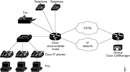
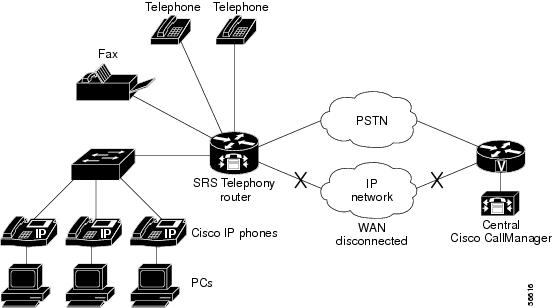
Figure 2 shows that the WAN connection to the branch office is down and the Cisco IP phones are able to make calls by being connected to the Cisco IP Telephony router with the SRS Telephony feature. This router acts as a fallback Cisco CallManager. The branch office Cisco IP phones on the LAN network, connected to the PSTN, are capable of making off-net calls outside the network using the SRS Telephony router.
Figure 2 Branch Office Cisco IP Phones Operating in Survivable Remote Site (SRS) Telephony Mode
Benefits
•
•
Restrictions
•
•
Note
•
•
•
•
•
Note
Related Documents
•
•
•
•
•
•
•
Related Information
•
Supported Platforms
•
Note
•
•
•
Note
•
Supported Standards, MIBs, and RFCs
Standards
No new or modified standards are supported by this feature.
MIBs
No new or modified MIBs are supported by this feature.
To obtain lists of supported MIBs by platform and Cisco IOS release, and to download MIB modules, go to the Cisco MIB web site on Cisco.com at the following URL:
http://www.cisco.com/public/sw-center/netmgmt/cmtk/mibs.shtml
RFCs
No new or modified RFCs are supported by this feature.
Prerequisites
•
•
•
•
•
•
Note
•
Configuration Tasks
See the following sections for configuration tasks for the SRS Telephony feature. Each task in the list is identified as either required or optional.
•
•
•
Configuring Survivable Remote Site Telephony (required)

Tip
To configure Survivable Remote Site (SRS) Telephony on the routers to support the Cisco IP phone functions, use the following commands beginning in global configuration mode:
Step 1
Router(config)# call-manager-fallback
Enables Survivable Remote Site (SRS) Telephony feature support and enters call-manager-fallback mode.
Step 2
Router(config-cm-fallback)# ip source-address ip-address port port
Enables the router to receive messages from the Cisco IP phones through the specified IP addresses and ports. The default port is 2000.
Step 3
Router(config-cm-fallback)#
max-ephones max phonesConfigures the maximum number of Cisco IP phones that can be supported by the router. The default is 0. The maximum number is platform dependent:
•
•
•
•
•
•
•
–
–
–
–
See Table 1 for details.
Note
Step 4
Router(config-cm-fallback)#
max-dn max directory numbersSets the maximum number of directory numbers or virtual voice ports that can be supported by the router. The default is 0. The maximum number is platform dependent:
•
•
•
•
•
•
•
–
–
–
–
See Table 1 for details.
Note
Step 5
Router(config-cm-fallback)#
keepalive seconds(Optional) Configures the time interval between sending keepalive messages to the router used by the Cisco IP phones when SRS Telephony is enabled. The default is 30 seconds.
Step 6
Router(config-cm-fallback)#
default-destination telephone number(Optional) Assigns default destination number for incoming telephone calls.
Step 7
Router(config-cm-fallback)#
dialplan-pattern tag pattern extension-length number(Optional) Creates a global prefix that can be used to expand the abbreviated extension numbers into fully qualified E.164 numbers. The extension-length keyword enables the system to convert a full E.164 telephone number back to an extension number for the purposes of caller ID display, received, and missed call lists.
Step 8
Router(config-cm-fallback)#
transfer-pattern transfer-pattern(Optional) Allows transfer of telephone calls by Cisco IP phones to other phone numbers (IP and non-IP phone numbers).
Step 9
Router(config-cm-fallback)#
access-code {bri | e&m |fxo | pri}(Optional) Configures trunk access codes for each type of line—Basic Rate Interface (BRI), E&M, Foreign Exchange Office (FXO), and Primary Rate Interface (PRI)— so that the Cisco IP phones can access the trunk lines during Cisco CallManager fallback mode when the SRS Telephony feature is enabled.
Step 10
Router(config-cm-fallback)#
voicemail phone-number(Optional) Configures the telephone number that is speed-dialed when the message button on a Cisco IP phone is pressed.
Step 11
Router(config-cm-fallback)# timeouts interdigit seconds
(Optional) Configures the interdigit timeout value for all Cisco IP phones attached to the router. The interdigit timeout specifies the number of seconds that the system waits after the caller has entered the initial digit or a subsequent digit of the dialed string. If the timeout ends before the destination is identified, a tone sounds and the call ends.
Note
The seconds argument is the interdigit timeout wait time in seconds. A valid entry is an integer from 2 to 120 seconds. The default is 10 seconds.
Step 12
Router(config-cm-fallback)#
exitExits from call-manager-fallback configuration mode.
Step 13
Router(config)# exit
Exits from global configuration mode.
Disabling and Reenabling Huntstop
Note
To disable huntstop or to reenable huntstop, use the following command in call-manager-configuration mode:
Step 1
Router(config-cm-fallback)#
no huntstopDisables huntstop.
Step 1
Router(config-cm-fallback)#
huntstopEnables huntstop.
Verifying Survivable Remote Site Telephony (optional)
To verify that the SRS Telephony feature is enabled, follow these steps:
Step 1
Step 2
Step 3
Step 4
a.
Note
The Cisco IP Phone 7910 displays the message "CM Fallback Service" every 30 seconds for 5 seconds on the display screen because the Cisco IP Phone 7910 has a 2-line display area and the display panel is also used to display the telephone number.
b.
c.
d.
Troubleshooting Tips (optional)
To troubleshoot the SRS Telephony feature, perform the following steps:
Step 1
Step 2
Step 3
To troubleshoot other areas of the SRS Telephony feature, use the following commands:
•
•
•
•
•
For further debugging, you can use the debug commands in the Cisco IOS Debug Command Reference.
Monitoring and Maintaining Survivable Remote Site Telephony
Use the following commands to monitor and maintain the router with SRS Telephony feature:
Configuration Examples
This section provides the following configuration example for the SRS Telephony feature:
!version 12.2no service single-slot-reload-enableservice timestamps debug uptimeservice timestamps log uptimeno service password-encryption!!logging rate-limit console 10 except errors!!!ip subnet-zero!!no ip fingerno ip domain-lookup!ip dhcp pool PHONE1host 10.1.0.2 255.255.0.0client-identifier 0100.3094.c337.cboption 150 ip 172.198.0.2default-router 10.1.0.1!ip dhcp pool PHONE2host 10.1.0.3 255.255.0.0client-identifier 0100.3094.c3f9.6adefault-router 10.1.0.1option 150 ip 172.198.0.2!!!!!!!!interface FastEthernet0/0ip address 10.1.0.1 255.255.0.0duplex autospeed auto!interface FastEthernet0/1ip address 172.198.0.1 255.255.0.0duplex autospeed auto!ip kerberos source-interface anyip classlessno ip http server!!snmp-server packetsize 4096snmp-server managercall rsvp-sync!mgcp modem passthrough voip mode cano mgcp timer receive-rtcp!mgcp profile default!dial-peer cor custom!!!!call-manager-fallbackip source-address 10.1.0.1 port 2000 strict-matchmax-ephones 24max-dn 24dialplan-pattern 1 408734.... extension-length 4transfer-pattern 510650....voicemail 11111!!line con 0transport input noneline aux 0line vty 0 4login!endCommand Reference
This section documents new commands. All other commands used with the Survivable Remote Site (SRS) Telephony feature are documented in the Cisco IOS Release 12.2 command reference publications.
•
•
•
•
•
•
•
•
•
access-code (cm-fallback)
To configure trunk access codes for each type of line so that the Cisco IP phones can access the trunk lines only during Cisco CallManager fallback mode when Survivable Remote Site (SRS) Telephony feature is enabled, use the access-code call-manager-fallback configuration command. To remove the telephone access code configuration from the Cisco IP phones, use the no form of this command.
access-code {fxo | e&m | bri | pri} dial-string
no access-code {fxo | e&m | bri | pri} [dial-string]
Syntax Description
Defaults
No default behavior or values.
Command Modes
Call-manager-fallback configuration
Command History
Usage Guidelines
The access-code command configures trunk access codes for each type of line—BRI, E&M, FXO, and PRI—so that the Cisco IP phones can access the trunk lines in Cisco CallManager fallback mode when the Survivable Remote Site (SRS) Telephony feature is enabled. This provides system-wide access.
Note
The access-code command creates temporary POTS voice dial-peers for all router voice-ports of the selected type, during the time Cisco CallManager fallback mode is active. To remove the telephone access code configuration from the Cisco IP phones, use the no form of this command. Use this command only if your normal network dialplan configuration prevents you from configuring permanent POTS voice dial-peers to provide trunk access for use in the fallback mode. When the access-code command is used, it is important to ensure that all ports covered by the command have valid trunk connections. Selection between ports for outgoing calls is random.
The dialstring is used to set up temporary dial peers for each specified line type. If there are multiple lines of the same type, then a dial peer is set up for each line. The dial peers are active only during Cisco CallManager fallback mode when Survivable Remote Site (SRS) Telephony feature is enabled. The result of this configuration is that all PSTN interfaces of the same type, for example BRI, are treated as equivalent, and any port may be selected to place the outgoing PSTN call.
Note
Examples
The following example shows how to set the access-code command for BRI 8:
Router(config)# call-manager-fallbackRouter(config-cm-fallback)# access-code bri 8The following example shows how to set the access-code command for E&M 8:
Router(config)# call-manager-fallbackRouter(config-cm-fallback)# access-code e&m 8The following example shows how to set the access-code command for FXO 9:
Router(config)# call-manager-fallbackRouter(config-cm-fallback)# access-code fxo 9The following example shows how to set the access-code command for PRI 9:
Router(config)# call-manager-fallbackRouter(config-cm-fallback)# access-code pri 9Related Commands
call-manager-fallback
Enables Survivable Remote Site (SRS) Telephony feature support and enters call-manager-fallback configuration mode.
call-manager-fallback
To enable Survivable Remote Site (SRS) Telephony support and enter call-manager-fallback mode, use the call-manager-fallback global configuration command. To disable SRS Telephony (call-manager-fallback mode) support, use the no form of this command.
call-manager-fallback
no call-manager-fallback
Syntax Description
This command has no argument or keywords.
Defaults
No default behavior or values.
Command Modes
Global configuration
Command History
Usage Guidelines
The call-manager-fallback command is a top-level command for all other commands related to call-manager-fallback configuration.
Examples
The following example shows how to enter the call-manager-fallback configuration mode:
Router(config)# call-manager-fallbackRouter(config-cm-fallback)#Related Commands
debug ephone detail
To set detail debugging for the Cisco IP phone, use the debug ephone detail debug command. To disable debugging, use the no form of this command.
debug ephone detail [mac-address mac-address]
no debug ephone detail [mac-address mac-address]
Syntax Description
mac-address
(Optional) Defines the MAC address of the Cisco IP phone.
mac-address
(Optional) Specifies the MAC address of the Cisco IP phone.
Command Modes
Privileged EXEC
Command History
Usage Guidelines
The debug ephone detail command includes the error and state levels.
If the mac-address keyword is not used, the debug ephone detail debug command debugs all Cisco IP phones that are registered to the router. You can remove debugging for the Cisco IP phones that you do not want to debug by using the mac-address keyword with the no form of this command.
Debugging can be enabled or disabled on any number of Cisco IP phones. The Cisco IP phones that have debugging enabled can be seen by entering the show ephone command and looking at the debug field in the output. When debugging is enabled for a Cisco IP phone, the debug output is displayed for any Cisco IP phone directory numbers or virtual voice ports associated with the Cisco IP phone.
Examples
The following example shows a sample output of detail debugging of the Cisco IP phone with MAC address 0030.94c3.8724. The sample is an excerpt of some of the activities that takes place during call setup, connected state, active call, and the call getting disconnected:
Router# debug ephone detail mac-address 0030.94c3.8724Ephone detail debugging is enabled1d04h: ephone-1[1]:OFFHOOK..1d04h: Skinny Call State change for DN 1 SIEZE..1d04h: ephone-1[1]:SetCallState line 1 DN 1 TsOffHook..1d04h: ephone-1[1]:SetLineLamp 1 to ON..1d04h: ephone-1[1]:KeypadButtonMessage 5..1d04h: ephone-1[1]:KeypadButtonMessage 0..1d04h: ephone-1[1]:KeypadButtonMessage 0..1d04h: ephone-1[1]:KeypadButtonMessage 2..1d04h: ephone-1[1]:Store ReDial digit: 5002.SkinnyTryCall to 5002 instance 1..1d04h: ephone-1[1]:Store ReDial digit: 50021d04h: ephone-1[1]:SkinnyTryCall to 5002 instance 1..1d04h: Skinny Call State change for DN 1 ALERTING..1d04h: ephone-1[1]:SetCallState line 1 DN 1 TsRingOut..1d04h: ephone-1[1]:SetLineLamp 1 to ON1d04h: SetCallInfo calling dn 1 dn 1calling [5001] called [5002]..1d04h: ephone-1[1]: Jane calling1d04h: ephone-1[1]: Jill..1d04h: SkinnyUpdateDnState by EFXS_RING_GENERATEfor DN 2 to state RINGING..1d04h: SkinnyGetCallState for DN 2 CONNECTED..1d04h: ephone-1[1]:SetLineLamp 3 to ON1d04h: ephone-1[1]:UpdateCallState DN 1 state 4 calleddn 2..1d04h: Skinny Call State change for DN 1 CONNECTED..1d04h: ephone-1[1]:OpenReceive DN 1 codec 4:G711Ulaw64k duration 10 ms bytes 80..1d04h: ephone-1[1]:OpenReceiveChannelAck 1.2.172.21 port=201801d04h: ephone-1[1]:Outgoing calling DN 1 Far-ephone-2 called DN 21d04h: SkinnyGetCallState for DN 1 CONNECTED..1d04h: ephone-1[1]:SetCallState line 3 DN 2 TsOnHook..1d04h: ephone-1[1]:SetLineLamp 3 to OFF..1d04h: ephone-1[1]:SetCallState line 1 DN 1 TsOnHook..1d04h: ephone-1[1]:Clean Up Speakerphone state1d04h: ephone-1[1]:SpeakerPhoneOnHook1d04h: ephone-1[1]:Clean up activeline 11d04h: ephone-1[1]:StopTone sent to ephone1d04h: ephone-1[1]:Clean Up phone offhook state1d04h: SkinnyGetCallState for DN 1 IDLE1d04h: called DN -1, calling DN -1 phone -11d04h: ephone-1[1]:SetLineLamp 1 to OFF1d04h: UnBinding ephone-1 from DN 11d04h: UnBinding called DN 2 from DN 11d04h: ephone-1[1]:ONHOOK1d04h: ephone-1[1]:SpeakerPhoneOnHook1d04h: ephone-1[1]:ONHOOK NO activeline...Related Commands
debug ephone error
To set error debugging for the Cisco IP phone, use the debug ephone error debug command. To disable debugging, use the no form of this command.
debug ephone error [mac-address mac-address]
no debug ephone error [mac-address mac-address]
Syntax Description
mac-address
(Optional) Defines the MAC address of the Cisco IP phone.
mac-address
(Optional) Specifies the MAC address of the Cisco IP phone.
Command Modes
Privileged EXEC
Command History
Usage Guidelines
The debug phone error command cancels debugging at the detail and state level. This command is used to detect significant internal errors.
If the mac-address keyword is not used, the debug ephone error debug command debugs all Cisco IP phones that are registered to the router. You can remove debugging for the Cisco IP phones that you do not want to debug by using the mac-address keyword with the no form of this command.
Debugging can be enabled or disabled on any number of Cisco IP phones. The Cisco IP phones that have debugging enabled can be seen by entering the show ephone command and looking at the debug field in the output. When debugging is enabled for a Cisco IP phone, the debug output is displayed for any Cisco IP phone directory numbers or virtual voice ports associated with the Cisco IP phone.
Examples
The following example shows a sample output of error debugging for the Cisco IP phone with MAC address 0030.94c3.8724:
Router# debug ephone error mac-address 0030.94c3.8724EPHONE error debugging is enabledsocket [2] send ERROR 11Skinny Socket [2] retry failureRelated Commands
debug ephone keepalive
To set keepalive debugging for the Cisco IP phone, use the debug ephone keepalive debug command. To disable debugging, use the no form of this command.
debug ephone keepalive [mac-address mac-address]
no debug ephone keepalive [mac-address mac-address]
Syntax Description
mac-address
(Optional) Defines the MAC address of the Cisco IP phone.
mac-address
(Optional) Specifies the MAC address of the Cisco IP phone.
Command Modes
Privileged EXEC
Command History
Usage Guidelines
The debug ephone keepalive command sets keepalive debugging.
If the mac-address keyword is not used, the debug ephone keepalive debug command debugs all Cisco IP phones that are registered to the router. You can remove debugging for the Cisco IP phones that you do not want to debug by using the mac-address keyword with the no form of this command.
Debugging can be enabled or disabled on any number of Cisco IP phones. The Cisco IP phones that have debugging enabled can be seen by entering the show ephone command and looking at the debug field in the output. When debugging is enabled for a Cisco IP phone, the debug output is displayed for any Cisco IP phone directory numbers or virtual voice ports associated with the Cisco IP phone.
Examples
The following example shows a sample output of the keepalive status for the Cisco IP phone with MAC address 0030.94C3.E1A8:
Router# debug ephone keepalive mac-address 0030.94c3.E1A8EPHONE keepalive debugging is enabled for phone 0030.94C3.E1A81d05h: ephone-1 Set interface FastEthernet0/0 ETHERNET1d05h: ephone-1[1]:Keepalive socket[1] SEP003094C3E1A81d05h: ephone-1 Set interface FastEthernet0/0 ETHERNET1d05h: ephone-1[1]:Keepalive socket[1] SEP003094C3E1A81d05h: Skinny Checking for stale sockets1d05h: ephone-1 Set interface FastEthernet0/0 ETHERNET1d05h: ephone-1[1]:Keepalive socket[1] SEP003094C3E1A81d05h: ephone-1 Set interface FastEthernet0/0 ETHERNET1d05h: ephone-1[1]:Keepalive socket[1] SEP003094C3E1A81d05h: Skinny active socket list (3/96): 1 2 4Related Commands
debug ephone pak
To provide voice packet level debugging and to print the contents of one voice packet in every 1024 voice packets, use the debug ephone pak debug command. To disable debugging, use the no form of this command.
debug ephone pak [mac-address mac-address]
no debug ephone pak [mac-address mac-address]
Syntax Description
mac-address
(Optional) Defines the MAC address of the Cisco IP phone.
mac-address
(Optional) Specifies the MAC address of the Cisco IP phone.
Command Modes
Privileged EXEC
Command History
Usage Guidelines
The debug ephone pak command provides voice packet level debugging and prints the contents of one voice packet in every 1024 voice packets.
If the mac-address keyword is not used, the debug ephone pak debug command debugs all Cisco IP phones that are registered to the router. You can remove debugging for the Cisco IP phones that you do not want to debug by using the mac-address keyword with the no form of this command.
Debugging can be enabled or disabled on any number of Cisco IP phones. The Cisco IP phones that have debugging enabled can be seen by entering the show ephone command and looking at the debug field in the output. When debugging is enabled for a Cisco IP phone, the debug output is displayed for any Cisco IP phone directory numbers or virtual voice ports associated with the Cisco IP phone.
Examples
The following example shows a sample output of packet debugging for the Cisco IP phone with MAC address 0030.94c3.8724:
Router# debug ephone pak mac-address 0030.94c3.8724EPHONE packet debugging is enabled01:29:14: ***ph_xmit_ephone DN 3 tx_pkts 5770 dest=10.2.1.1 orig len=32pakcopy=0 discards 27 ip_enctype 0 0 last discard: unsupported payload type01:29:14: to_skinny_duration 130210 offset -30 last -40 seq 0 adj 001:29:14: IP: 45B8 003C 0866 0000 3F11 3F90 2800 0001 0A02 010101:29:14: TTL 63 TOS B8 prec 501:29:14: UDP: 07D0 6266 0028 000001:29:14: sport 2000 dport 25190 length 40 checksum 001:29:14: RTP: 8012 16AF 9170 6409 0E9F 000101:29:14: is_rtp:1 is_frf11:0 vlen:0 delta_t:160 vofr1:0 vofr2:0scodec:11 rtp_bits:8012 rtp_codec:18 last_bad_payload 1901:29:14: vencap FAILED01:29:14: PROCESS SWITCH01:29:15: %SYS-5-CONFIG_I: Configured from console by console01:29:34: ***SkinnyPktIp DN 3 10.2.1.1 to 40.0.0.1 pkts 4880 FAST sw01:29:34: from_skinny_duration 15091001:29:34: nw 3BBC2A8 addr 3BBC2A4 mac 3BBC2A4 dg 3BBC2C4 dgs 2A01:29:34: MAC: 1841 080001:29:34: IP: 45B8 0046 682E 0000 3E11 E0BD 0A02 0101 2800 000101:29:34: TTL 62 TOS B8 prec 501:29:34: UDP: 6266 07D0 0032 000001:29:34: sport 25190 dport 2000 length 50 checksum 001:29:34: RTP: 8012 55FF 0057 8870 3AF4 C39401:29:34: RTP: rtp_bits 8012 seq 55FF ts 578870 ssrc 3AF4C39401:29:34: PAYLOAD:01:29:34: 1409 37C9 54DE 449C 3B42 0446 3AAB 182E01:29:34: 56BC 5184 58E5 56D3 13BE 44A7 B8C401:29:34:01:29:37: ***ph_xmit_ephone DN 3 tx_pkts 6790 dest=10.2.1.1 orig len=32pakcopy=0 discards 31 ip_enctype 0 0 last discard: unsupported payload type01:29:37: to_skinny_duration 153870 offset -150 last -40 seq 0 adj 001:29:37: IP: 45B8 003C 0875 0000 3F11 3F81 2800 0001 0A02 010101:29:37: TTL 63 TOS B8 prec 501:29:37: UDP: 07D0 6266 0028 000001:29:37: sport 2000 dport 25190 length 40 checksum 001:29:37: RTP: 8012 1AAF 9173 4769 0E9F 000101:29:37: is_rtp:1 is_frf11:0 vlen:0 delta_t:160 vofr1:0 vofr2:0Related Commands
debug ephone raw
To provide raw low-level protocol debugging display for all Skinny Client Control Protocol messages, use the debug ephone raw debug command. To disable debugging, use the no form of this command.
debug ephone raw [mac-address mac-address]
no debug ephone raw [mac-address mac-address]
Syntax Description
mac-address
(Optional) Defines the MAC address of the Cisco IP phone.
mac-address
(Optional) Specifies the MAC address of the Cisco IP phone.
Command Modes
Privileged EXEC
Command History
Usage Guidelines
The debug ephone raw command provides raw low-level protocol debug display for all Skinny Client Control Protocol messages. The debug display provides byte level display of Skinny TCP socket messages.
If the mac-address keyword is not used, the debug ephone raw debug command debugs all Cisco IP phones that are registered to the router. You can remove debugging for the Cisco IP phones that you do not want to debug by using the mac-address keyword with the no form of this command.
Debugging can be enabled or disabled on any number of Cisco IP phones. The Cisco IP phones that have debugging enabled can be seen by entering the show ephone command and looking at the debug field in the output. When debugging is enabled for a Cisco IP phone, the debug output is displayed for any Cisco IP phone directory numbers or virtual voice ports associated with the Cisco IP phone.
Examples
The following example shows a sample output of raw protocol debugging for the Cisco IP phone with MAC address 0030.94C3.E1A8:
Router# debug ephone raw mac-address 0030.94c3.E1A8EPHONE raw protocol debugging is enabled for phone 0030.94C3.E1A81d05h: skinny socket received 4 bytes on socket [1]0 0 0 01d05h:1d05h: SkinnyMessageID = 01d05h: skinny send 4 bytes4 0 0 0 0 0 0 0 0 1 0 01d05h: socket [1] sent 12 bytes OK (incl hdr) for ephone-(1)1d06h: skinny socket received 4 bytes on socket [1]0 0 0 01d06h:1d06h: SkinnyMessageID = 01d06h: skinny send 4 bytes4 0 0 0 0 0 0 0 0 1 0 01d06h: socket [1] sent 12 bytes OK (incl hdr) for ephone-(1)Related Commands
debug ephone register
To set registration debugging for the Cisco IP phone, use the debug ephone register debug command. To disable debugging, use the no form of this command.
debug ephone register [mac-address mac-address]
no debug ephone register [mac-address mac-address]
Syntax Description
mac-address
(Optional) Defines the MAC address of the Cisco IP phone.
mac-address
(Optional) Specifies the MAC address of the Cisco IP phone.
Command Modes
Privileged EXEC
Command History
Usage Guidelines
The debug ephone register command sets registration debugging for the Cisco IP phones.
If the mac-address keyword is not used, the debug ephone register debug command debugs all Cisco IP phones that are registered to the router. You can remove debugging for the Cisco IP phones that you do not want to debug by using the mac-address keyword with the no form of this command.
Debugging can be enabled or disabled on any number of Cisco IP phones. The Cisco IP phones that have debugging enabled can be seen by entering the show ephone command and looking at the debug field in the output. When debugging is enabled for a Cisco IP phone, the debug output is displayed for any Cisco IP phone directory numbers or virtual voice ports associated with the Cisco IP phone.
Syntax Description
The following example shows a sample output of registration debugging for the Cisco IP phone with MAC address 0030.94c3.8724:
Router# debug ephone register mac-address 0030.94c3.8724Ephone registration debugging is enabled1d06h: New Skinny socket accepted [1] (2 active)1d06h: sin_family 2, sin_port 50778, in_addr 10.1.0.211d06h: skinny_add_socket 1 10.1.0.21 507781d06h: ephone-(1)[1] StationRegisterMessage (2/3/12) from 10.1.0.211d06h: ephone-(1)[1] Register StationIdentifier DeviceName SEP003094C3E1A81d06h: ephone-(1)[1] StationIdentifier Instance 1 deviceType 71d06h: ephone-1[-1]:stationIpAddr 10.1.0.211d06h: ephone-1[-1]:maxStreams 01d06h: ephone-(1) Allow any Skinny Server IP address 10.1.0.6...1d06h: ephone-1[1]:RegisterAck sent to ephone 1: keepalive period 30..Related Commands
debug ephone state
To set state debugging for the Cisco IP phone, use the debug ephone state debug command. To disable debugging, use the no form of this command.
debug ephone state [mac-address mac-address]
no debug ephone state [mac-address mac-address]
Syntax Description
mac-address
(Optional) Defines the MAC address of the Cisco IP phone.
mac-address
(Optional) Specifies the MAC address of the Cisco IP phone.
Command Modes
Privileged EXEC
Command History
Usage Guidelines
The debug ephone state command sets state debugging for the Cisco IP phones.
If the mac-address keyword is not used, the debug ephone state debug command debugs all Cisco IP phones that are registered to the router. You can remove debugging for the Cisco IP phones that you do not want to debug by using the mac-address keyword with the no form of this command.
Debugging can be enabled or disabled on any number of Cisco IP phones. The Cisco IP phones that have debugging enabled can be seen by entering the show ephone command and looking at the debug field in the output. When debugging is enabled for a Cisco IP phone, the debug output is displayed for any Cisco IP phone directory numbers or virtual voice ports associated with the Cisco IP phone.
Examples
The following example shows a sample output of state debugging for the Cisco IP phone with MAC address 0030.94c3.E1A8:
Router# debug ephone state mac-address 0030.94c3.E1A8EPHONE state debugging is enabled for phone 0030.94C3.E1A81d06h: ephone-1[1]:OFFHOOK1d06h: ephone-1[1]:SIEZE on activeline 01d06h: ephone-1[1]:SetCallState line 1 DN 1 TsOffHook1d06h: ephone-1[1]:Skinny-to-Skinny call DN 1 to DN 2 instance 11d06h: ephone-1[1]:SetCallState line 1 DN 1 TsRingOut1d06h: ephone-1[1]:Call Info DN 1 line 1 ref 158 called 5002 calling 50011d06h: ephone-1[1]: Jane calling1d06h: ephone-1[1]: Jill1d06h: ephone-1[1]:SetCallState line 3 DN 2 TsRingIn1d06h: ephone-1[1]:Call Info DN 2 line 3 ref 159 called 5002 calling 50011d06h: ephone-1[1]: Jane calling1d06h: ephone-1[1]: Jill1d06h: ephone-1[1]:SetCallState line 3 DN 2 TsCallRemoteMultiline1d06h: ephone-1[1]:SetCallState line 1 DN 1 TsConnected1d06h: ephone-1[1]:OpenReceive DN 1 codec 4:G711Ulaw64k duration 10 ms bytes 801d06h: ephone-1[1]:OpenReceiveChannelAck 1.2.172.21 port=240101d06h: ephone-1[1]:StartMedia 1.2.172.22 port=246121d06h: DN 1 codec 4:G711Ulaw64k duration 10 ms bytes 801d06h: ephone-1[1]:CloseReceive1d06h: ephone-1[1]:StopMedia1d06h: ephone-1[1]:SetCallState line 3 DN 2 TsOnHook1d06h: ephone-1[1]:SetCallState line 1 DN 1 TsOnHook1d06h: ephone-1[1]:SpeakerPhoneOnHook1d06h: ephone-1[1]:ONHOOK1d06h: ephone-1[1]:SpeakerPhoneOnHook1d06h: SkinnyReportDnState DN 1 ONHOOKRelated Commands
debug ephone statistics
To set call statistics debugging for the Cisco IP phone, use the debug ephone statistics debug command. To disable debugging, use the no form of this command.
debug ephone statistics [mac-address mac-address]
no debug ephone statistics [mac-address mac-address]
Syntax Description
mac-address
(Optional) Defines the MAC address of the Cisco IP phone.
mac-address
(Optional) Specifies the MAC address of the Cisco IP phone.
Command Modes
Privileged EXEC
Command History
Usage Guidelines
The debug ephone statistics command provides a debug monitor display of the periodic messages from the Cisco IP phone to the router. These include transmit-and-receive packet counts and an estimate of drop packets. The call statistics can also be displayed for live calls using the show ephone command.
If the mac-address keyword is not used, the debug ephone statistics debug command debugs all Cisco IP phones that are registered to the router. You can remove debugging for the Cisco IP phones that you do not want to debug by using the mac-address keyword with the no form of this command.
Debugging can be enabled or disabled on any number of Cisco IP phones. The Cisco IP phones that have debugging enabled can be seen by entering the show ephone command and looking at the debug field in the output. When debugging is enabled for a Cisco IP phone, the debug output is displayed for any Cisco IP phone directory numbers or virtual voice ports associated with the Cisco IP phone.
Examples
The following example shows a sample output of statistics debugging for the Cisco IP phone with MAC address 0030.94C3.E1A8:
Router# debug ephone statistics mac-address 0030.94C3.E1A8EPHONE statistics debugging is enabled for phone 0030.94C3.E1A81d06h: Clear Call Stats for DN 1 call ref 1621d06h: Clear Call Stats for DN 1 call ref 1621d06h: Clear Call Stats for DN 1 call ref 1621d06h: Clear Call Stats for DN 2 call ref 1631d06h: ephone-1[1]:GetCallStats line 1 ref 162 DN 1: 50011d06h: ephone-1[1]:Call Stats for line 1 DN 1 5001 ref 1621d06h: ephone-1[1]:TX Pkts 0 bytes 0 RX Pkts 0 bytes 01d06h: ephone-1[1]:Pkts lost 4504384 jitter 0 latency 01d06h: ephone-1[1]:Src 0.0.0.0 0 Dst 0.0.0.0 0 bytes 80 vad 0 G711Ulaw64k1d06h: ephone-1[1]:GetCallStats line 1 ref 162 DN 1: 50011d06h: STATS: DN 1 Packets Sent 01d06h: STATS: DN 2 Packets Sent 01d06h: ephone-1[1]:Call Stats found DN -1 from Call Ref 1621d06h: ephone-1[1]:Call Stats for line 0 DN -1 5001 ref 1621d06h: ephone-1[1]:TX Pkts 275 bytes 25300 RX Pkts 275 bytes 253001d06h: ephone-1[1]:Pkts lost 0 jitter 0 latency 0Related Commands
default-destination (cm-fallback)
To assign a default destination number for incoming telephone calls on the Survivable Remote Site (SRS) Telephony router, use the default-destination call-manager-fallback configuration command. To disable the default destination number on the SRS Telephony router, use the no form of this command.
default-destination telephone number
no default-destination telephone number
Syntax Description
Defaults
No default behavior or values.
Command Modes
Call-manager-fallback configuration
Command History
Usage Guidelines
The default-destination command assigns default destination numbers when an incoming call on an FXO port arrives without the called number information. A default directory number is required to route the call.
If a default destination number is set, calls arriving on an FXO port are routed to the default destination number that is provided. If a default destination number is not set, the calls arriving on an FXO port receive (secondary) dial tone. Then you need to enter the extension number of the person you are trying to reach.
Examples
The following example shows how to set the default destination as 40802:
Router(config)# call-manager-fallbackRouter(config-cm-fallback)# default-destination 40802Related Commands
call-manager-fallback
Enables Survivable Remote Site (SRS) Telephony feature support and enters call-manager-fallback configuration mode.
dialplan-pattern (cm-fallback)
To create a global prefix that can be used to expand the abbreviated extension numbers (automatically obtained from the Cisco IP phones) to expand into fully qualified E.164 numbers, use the dialplan-pattern call-manager-fallback configuration command. To disable a global prefix, use the no form of this command.
dialplan-pattern tag pattern extension-length length
no dialplan-pattern tag [pattern extension-length length]
Syntax Description
Defaults
No default behavior or values.
Command Modes
Call-manager-fallback configuration
Command History
Usage Guidelines
You need to enter the directory numbers or virtual voice ports for the Cisco IP phones in extension number format. The extension number should be greater or equal to the extension length. Otherwise, the extension number cannot be converted to a qualified E.164 number. The dialplan-pattern command creates a global prefix that can be used to expand the abbreviated extension numbers to fully qualified E.164 numbers. The dialplan pattern is also required to register the Cisco IP phone lines with a gatekeeper. The dialplan-pattern command can resolve an incoming call into a fully qualified E.164 number.
The extension-length keyword enables the system to convert a full E.164 telephone number back to an extension number for the purposes of caller ID display, received, and missed call lists. For example, a company uses extension number range 5000-5099 across several sites, with only the extensions 5000-5009 present on the local router. An incoming call from 5044 arrives from the company's internal ISDN network and this call includes the calling number as 4083335044 in its full E.164 format.
Examples
The following example shows how to create dialplan-pattern 1 for extension numbers 5001 to 5099 with the telephone prefix starting with 408333. If the following example is set, the router sees that the 4083335044 matches dialplan pattern 1, and uses the extension-length keyword to extract the last four digits of the number 5044 and present this as the caller ID for the incoming call.
Router(config)# call-manager-fallbackRouter(config-cm-fallback)# dialplan-pattern 1 40833350.. extension-length 4Related Commands
call-manager-fallback
Enables Survivable Remote Site (SRS) Telephony feature support and enters call-manager-fallback configuration mode.
huntstop (cm-fallback)
To set the huntstop attribute for the dial peers associated with the Cisco IP phone phone lines when the Survivable Remote Site (SRS) Telephony feature is enabled, use the huntstop call-manager-fallback configuration command. To disable huntstop, use the no form of this command.
huntstop
no huntstop
Syntax Description
This command has no arguments or keywords.
Defaults
Huntstop is set by default.
Command Modes
Call-manager-fallback configuration
Command History
Usage Guidelines
In the call-manager-fallback configuration mode, the huntstop attribute by default is set uniformly to all Cisco IP phone lines (for example, all or none).
Note
Examples
The following example shows how to disable huntstop to the destination dial peer with the extension 5001. The huntstop for the dial peer is set to OFF and prevents calls to extension 5001 from being re-routed to the on-net H-323 dial peer for 5... (The three decimal points are used here as wild cards.) destination when 5001 is busy.
Router(config)# call-manager-fallbackRouter(config-cm-fallback)# no huntstopRelated Commands
ip source-address (cm-fallback)
To enable the router to receive messages from the Cisco IP phones through the specified IP addresses and ports when the Survivable Remote Site (SRS) Telephony feature is enabled, use the ip source-address call-manager-fallback configuration command. To disable the router from receiving messages from the Cisco IP phones, use the no form of this command.
ip source-address ip-address [port port] [any-match | strict-match]
no ip source-address [ip-address port port] [any-match | strict-match]
Syntax Description
Defaults
The default port is 2000.
The default for the server address match is any-match.
Command Modes
Call-manager-fallback configuration
Command History
Usage Guidelines
The ip source-address command is a mandatory command, and the fallback subsystem does not start if the IP address is not provided. If the port number is not provided, then the default value (2000) is used. The IP address is usually the IP address of the Ethernet port to which the phones are connected.
Use the any-match keyword to instruct the router to permit Cisco IP phone registration even when the IP server address used by the phone does not match the ip source-address. This option can be used to allow registration of Cisco IP phones on different subnets that have different DHCP default-router or TFTP server addresses.
Use the strict-match keyword to instruct the router to reject Cisco IP phone registration attempts if the IP server address used by the phone does not exactly match the source-address. This option can be used to restrict the number of Cisco IP phones allowed to register, by dividing the Cisco IP phones into groups on different subnets and giving each group different DHCP default-router or TFTP server addresses.
The ip source-address command enables the router to receive messages from the Cisco IP phones through the specified IP addresses and port. If the router receives a registration request from a Cisco IP phone, the router in return requests the phone configuration and dial-plan information from the Cisco IP phone. This data is stored locally in the memory of the router and is used to create voice port and dial-plan information. The voice port and dial-plan information is used to handle telephony calls to and from the Cisco IP phone if the Cisco CallManager is unreachable.
Examples
The following example shows how to set the IP source address and port:
Router(config)# call-manager-fallbackRouter(config-cm-fallback)# ip source-address 1.6.21.4 port 2002 strict-matchRelated Commands
call-manager-fallback
Enables Survivable Remote Site (SRS) Telephony feature support and enters call-manager-fallback configuration mode.
keepalive (cm-fallback)
To configure the time interval between sending keepalive messages to the router used by the Cisco IP phones during Cisco CallManager fallback mode when Survivable Remote Site (SRS) Telephony feature is enabled, use the keepalive call-manager-fallback configuration command. To return to the default, use the no form of this command.
keepalive seconds
no keepalive seconds
Syntax Description
Defaults
30 seconds
Command Modes
Call-manager-fallback configuration
Command History
Usage Guidelines
The keepalive command configures the time interval between sending keepalive messages to the router used by the Cisco IP phones at the time. If the router fails to receive three successive keepalive messages, it considers the phone to be out of service until the phone re-registers.
Note
Examples
The following example shows how to set keepalive timeout at 60 seconds:
Router(config)# call-manager-fallbackRouter(config-cm-fallback)# keepalive 60Related Commands
call-manager-fallback
Enables Survivable Remote Site (SRS) Telephony feature support and enters call-manager-fallback configuration mode.
max-dn (cm-fallback)
To set the maximum number of directory numbers or virtual voice ports that can be supported by the router when the Survivable Remote Site (SRS) Telephony feature is enabled, use the max-dn call-manager-fallback configuration command. To return to the default directory numbers or virtual voice ports, use the no form of this command.
max-dn max directory numbers
no max-dn
Syntax Description
Defaults
The default is 0.
Command Modes
Call-manager-fallback configuration
Command History
Usage Guidelines
The max-dn command limits the number of Cisco IP phone directory numbers or virtual voice ports available on the router.
Note
Examples
The following example shows how to set the maximum number of directory numbers or virtual voice ports to 12:
Router(config)# call-manager-fallbackRouter(config-cm-fallback)# max-dn 12Related Commands
call-manager-fallback
Enables Survivable Remote Site (SRS) Telephony feature support and enters call-manager-fallback configuration mode.
max-ephones (cm-fallback)
To configure the maximum number of Cisco IP phones that can be supported by the router when the Survivable Remote Site (SRS) Telephony feature is enabled, use the max-ephones call-manager-fallback configuration command. To return to the default number of Cisco IP phones, use the no form of this command.
max-ephones max phones
no max-ephones
Syntax Description
Defaults
The default is 0.
Command Modes
Call-manager-fallback configuration
Command History
Usage Guidelines
The max-ephones command limits the number of Cisco IP phones supported on the router.
Note
Examples
The following example shows how to set the maximum Cisco IP phones to 24 for a Cisco router:
Router(config)# call-manager-fallbackRouter(config-cm-fallback)# max-ephones 24Related Commands
call-manager-fallback
Enables Survivable Remote Site (SRS) Telephony feature support and enters call-manager-fallback configuration mode.
reset (cm-fallback)
To reset the Cisco IP phones when the Survivable Remote Site (SRS) Telephony feature is enabled, use the reset call-manager-fallback configuration command.
reset {all | mac-address mac-address}
Note
Syntax Description
Defaults
No default behavior or values.
Command Modes
Call-manager-fallback configuration
Command History
Usage Guidelines
The reset command resets the Cisco IP phones attached to the router. You can use the all keyword to reset all the Cisco IP phones attached to the router or reset a specific Cisco IP phone by using the mac-address keyword and by entering the mac-address of that specific Cisco IP phone.
The reset command does not have a no form.
Examples
The following example shows how to reset all the Cisco IP phones:
Router(config)# call-manager-fallbackRouter(config-cm-fallback)# reset allThe following example shows how to reset the Cisco IP phone with the MAC address CFBA.321B.96FA:
Router(config)# call-manager-fallbackRouter(config-cm-fallback)# reset mac-address CFBA.321B.96FARelated Commands
call-manager-fallback
Enables Survivable Remote Site (SRS) Telephony feature support and enters call-manager-fallback configuration mode.
show call-manager-fallback all
To display the detailed configuration of all the Cisco IP phones, voice ports, and dial peers in your network during Cisco CallManager fallback mode when Survivable Remote Site (SRS) Telephony feature is enabled, use the show call-manager-fallback all EXEC command.
show call-manager-fallback all
Syntax Description
This command has no arguments or keywords.
Command Modes
EXEC
Command History
Examples
The following is sample output from the show call-manager-fallback all command:
Router# show call-manager-fallback allCONFIG======ip source-address 10.1.0.1 port 2000max-ephones 24max-dn 24huntstopvoicemail 11111keepalive 30ephone-dn 1number 1000huntstopephone-dn 2number 5003huntstopephone-dn 3number 9000huntstopephone-dn 4huntstop!!!voice-port 50/0/1station-id number 1000!voice-port 50/0/2station-id number 5003!voice-port 50/0/3station-id number 9000!voice-port 50/0/4!!!!dial-peer voice 20114 potsdestination-pattern 1000huntstopport 50/0/1dial-peer voice 20115 potsdestination-pattern 5003huntstopport 50/0/2dial-peer voice 20116 potsdestination-pattern 9000huntstopport 50/0/3dial-peer voice 20117 potshuntstopport 50/0/4Table 2 provides an alphabetical listing of the command fields in the sample output.
Related Commands
show call-manager-fallback dial-peer
To display output for the dial peers in Cisco CallManager fallback mode when Survivable Remote Site (SRS) Telephony feature is enabled, use the show call-manager-fallback dial-peer EXEC command.
show call-manager-fallback dial-peer
Syntax Description
This command has no arguments or keywords.
Command Modes
EXEC
Command History
Examples
The following is sample output from the show call-manager-fallback dial-peer command:
Router# show call-manager-fallback dial-peerdial-peer voice 20114 potsdestination-pattern 1000huntstopport 50/0/1dial-peer voice 20115 potsdestination-pattern 5003huntstopport 50/0/2dial-peer voice 20116 potsdestination-pattern 9000huntstopport 50/0/3dial-peer voice 20117 potsdestination-pattern 9001huntstopport 50/0/4dial-peer voice 20118 potsdestination-pattern 5007huntstopport 50/0/5dial-peer voice 20119 potsdestination-pattern 5017huntstopport 50/0/6dial-peer voice 20120 potsdestination-pattern 5001huntstopport 50/0/7dial-peer voice 20121 potshuntstopport 50/0/8Table 3 provides an alphabetical listing of the command fields in the sample output.
Related Commands
show call-manager-fallback ephone-dn
To display output for the Cisco IP phone directory numbers or virtual voice ports in Cisco CallManager fallback mode when the Survivable Remote Site (SRS) Telephony feature is enabled, use the show call-manager-fallback ephone-dn EXEC command.
show call-manager-fallback ephone-dn
Syntax Description
This command has no arguments or keywords.
Command Modes
EXEC
Command History
Examples
The following is sample output from the show call-manager-fallback ephone-dn command:
Router# show call-manager-fallback ephone-dnephone-dn 1number 1000huntstopephone-dn 2number 5003huntstopephone-dn 3number 9000huntstopephone-dn 4number 9001huntstopephone-dn 5huntstopTable 4 provides an alphabetical listing of the command fields in the sample output.
Table 4 show call-manager-fallback ephone-dn Field Descriptions
ephone-dn
Cisco IP phone directory number.
huntstop
Huntstop is set.
number
Cisco IP phone number.
Related Commands
show call-manager-fallback voice-port
To display output for the voice ports in Cisco CallManager fallback mode when Survivable Remote Site (SRS) Telephony feature is enabled, use the show call-manager-fallback voice-port EXEC command.
show call-manager-fallback voice-port
Syntax Description
This command has no arguments or keywords.
Command Modes
EXEC
Command History
Examples
The following is sample output from the show call-manager-fallback voice-port command:
Router# show call-manager-fallback voice-portvoice-port 50/0/1station-id number 8005!voice-port 50/0/2station-id number 8006!voice-port 50/0/3station-id number 8003!voice-port 50/0/4station-id number 8007!voice-port 50/0/5station-id number 8004!Table 5 provides an alphabetical listing of the command fields in the sample output.
Related Commands
show ephone
To display Cisco IP phone output, use the show ephone EXEC command.
show ephone [mac-address]
Syntax Description
Command Modes
EXEC
Command History
Usage Guidelines
The show ephone command displays the registered Cisco IP phones. If a MAC address is not specified, all phones are displayed.
Examples
The following is sample output from the show ephone command:
Router# show ephone
ephone-2 Mac:0030.94C3.F96A TCP socket:[2] activeLine:0 REGISTEREDmediaActive:0 offhook:0 ringing:0 reset:0 reset_sent:0 debug:0IP:10.1.1.2 52531 Telecaster 7960 keepalive 9button 1: dn 5 number 5007 CM Fallback IDLEbutton 2: dn 6 number 5017 CM Fallback IDLEephone-1 Mac:0030.94C3.37CB TCP socket:[4] activeLine:0 REGISTEREDmediaActive:0 offhook:0 ringing:0 reset:0 reset_sent:0 debug:0IP:10.1.1.1 51611 Telecaster 7910 keepalive 9button 1: dn 7 number 5001 CM Fallback IDLEephone-4 Mac:0030.94C3.F946 TCP socket:[3] activeLine:0 REGISTEREDmediaActive:0 offhook:0 ringing:0 reset:0 reset_sent:0 debug:0IP:10.2.1.2 51969 Telecaster 7960 keepalive 10button 1: dn 2 number 5003 CM Fallback IDLEbutton 2: dn 4 number 9001 CM Fallback IDLEephone-3 Mac:0030.94C3.F43A TCP socket:[1] activeLine:0 REGISTEREDmediaActive:0 offhook:0 ringing:0 reset:0 reset_sent:0 debug:0IP:10.2.1.1 51500 Telecaster 7960 keepalive 10button 1: dn 1 number 1000 CM Fallback IDLEbutton 2: dn 3 number 9000 CM Fallback IDLEThe following example shows how to display the status of the Cisco IP phone with the MAC address 0003.E3E7.F627:
Router# show ephone 0003.E3E7.F627ephone-1 Mac:0003.E3E7.F627 TCP socket:[1] activeLine:1 REGISTEREDmediaActive:1 offhook:1 ringing:0 reset:0 reset_sent:0 debug:0IP:10.0.0.51 50570 Telecaster 7940 keepalive 49button 1: dn 1 number 3001 CONNECTEDActive Call on DN 1:3001 10.0.0.51 31808 to 1.2.159.100 22708Tx Pkts 452 bytes 41584 Rx Pkts 452 bytes 41584 Lost 0Jitter 0 Latency 0Table 6 provides an alphabetical listing of the command fields in the sample output.
Related Commands
show ephone-dn
To display a Cisco IP phone destination number, use the show ephone-dn EXEC command.
show ephone-dn [tag | summary]
Syntax Description
tag
(Optional) Destination number tag. The destination number can be from 1 to 24.
summary
Summary of all Cisco IP phone destination number.
Command Modes
EXEC
Command History
Examples
The following is sample output from the show ephone-dn command:
Router# show ephone-dn 24EFXS 50/0/24 Slot is 50, Sub-unit is 0, Port is 24Type of VoicePort is EFXSOperation State is UPAdministrative State is UPNo Interface Down FailureDescription is not setNoise Regeneration is enabledNon Linear Processing is enabledMusic On Hold Threshold is Set to -38 dBmIn Gain is Set to 0 dBOut Attenuation is Set to 0 dBEcho Cancellation is enabledEcho Cancel Coverage is set to 8 msPlayout-delay Mode is set to defaultPlayout-delay Nominal is set to 60 msPlayout-delay Maximum is set to 200 msConnection Mode is normalConnection Number is not setInitial Time Out is set to 10 sInterdigit Time Out is set to 10 sRinging Time Out is set to 180 sCompanding Type is u-lawRegion Tone is set for USWait Release Time Out is 30 sStation name None, Station number NoneCaller ID Info Follows:Standard BELLCOREVoice card specific Info Follows:Digit Duration Timing is set to 100 msThe following is sample output from the show ephone-dn summary command:
Router# show ephone-dn summaryPORT DN STATE CODEC VAD VTSP STATE VPM STATE======== ========== ======== === ===================== =========50/0/1 DOWN - - - EFXS_ONHOOK50/0/2 DOWN - - - EFXS_ONHOOK50/0/3 DOWN - - - EFXS_ONHOOK50/0/4 INVALID - - - EFXS_INIT50/0/5 INVALID - - - EFXS_INIT50/0/6 INVALID - - - EFXS_INITTable 7 provides an alphabetical listing of the command fields in the sample output.
Related Commands
show ephone summary
To display a summary of all Cisco IP phones, use the show ephone summary EXEC command.
show ephone summary
Syntax Description
This command has no arguments or keywords.
Command Modes
EXEC
Command History
Usage Guidelines
The show ephone summary command is similar to the show ephone command. However, the show ephone summary command does not display the destination numbers listed. If you do not specify a MAC address, you get the status information about all the Cisco IP phones.
Examples
The following is sample output from the show ephone summary command:
Router# show ephone summaryephone-1 Mac:0030.94C3.37CB TCP socket:[1] activeLine:0 REGISTEREDmediaActive:0 offhook:0 ringing:0 reset:0 reset_sent:0 debug:1IP:10.1.1.1 Telecaster 7910 keepalive 75ephone-2 Mac:0030.94C3.F96A TCP socket:[2] activeLine:0 REGISTEREDmediaActive:0 offhook:0 ringing:0 reset:0 reset_sent:0 debug:1IP:10.1.1.2 Telecaster 7960 keepalive 90ephone-3 Mac:0030.94C3.F43A TCP socket:[-1] activeLine:0 DECEASEDmediaActive:0 offhook:0 ringing:0 reset:0 reset_sent:0 debug:1IP:10.2.1.1 Telecaster 7960 keepalive 2258ephone-4 Mac:0030.94C3.F946 TCP socket:[-1] activeLine:0 REGISTEREDmediaActive:0 offhook:0 ringing:0 reset:0 reset_sent:0 debug:1IP:0.0.0.0 Unknown 0 keepalive 0Table 8 provides an alphabetical listing of the command fields in the sample output.
Related Commands
timeouts interdigit (cm-fallback)
To configure the interdigit timeout value for all Cisco IP phones attached to the router when the Survivable Remote Site (SRS) Telephony feature is enabled, use the timeouts interdigit command in call-manager-fallback configuration mode. To disable the interdigit timeout value, use the no form of this command.
timeouts interdigit seconds
no timeouts interdigit seconds
Syntax Description
seconds
Interdigit timeout duration, set on the timer, in seconds for all the Cisco IP phones. Valid entries are any integer from 2 to 120.
Defaults
The default is 10 seconds.
Command Modes
Call-manager-fallback configuration
Command History
Usage Guidelines
The timeouts interdigit command specifies the number of seconds the system waits after a caller enters the initial digit or a subsequent digit of the dialed string. The timeouts interdigit timer is activated when the caller enters a digit and is restarted each time the caller enters subsequent digits until the destination address is identified. If the configured timeout value is exceeded before the destination address is identified, a tone sounds and the call is terminated. The default is 10 seconds.
To disable the timeouts interdigit timer, set the seconds value to zero.
Examples
The following example shows the interdigit timeout value set to 8 seconds for all Cisco IP phones:
Router(config)# call-manager-fallbackRouter(config-cm-fallback)# timeouts interdigit 8Related Commands
transfer-pattern (cm-fallback)
To allow transfer of telephone calls by Cisco IP phones to other phone numbers when the Survivable Remote Site (SRS) Telephony feature is enabled, use the transfer-pattern call-manager-fallback configuration command. To disable transfer of calls to other numbers, use the no form of this command.
transfer-pattern transfer-pattern
no transfer-pattern
Syntax Description
Defaults
Cisco IP phone to Cisco IP phone transfer
Command Modes
Call-manager-fallback configuration
Command History
Usage Guidelines
The transfer-pattern command allows you to transfer the call to non-IP phone numbers. The call is established between the other calling party and the new recipient. By default, all Cisco IP phone directory numbers or virtual voice ports are allowed as transfer targets.
Examples
The following example shows how to set the transfer pattern:
Router(config)# call-manager-fallbackRouter(config-cm-fallback)# transfer-pattern 52540..A maximum of 32 transfer patterns can be entered. In the previous example, 52540.. (The two decimal points are used here as wild cards.) permits transfers to any numbers in the range 525-4000 to 525-4099.Related Commands
call-manager-fallback
Enables Survivable Remote Site (SRS) Telephony feature support and enters call-manager-fallback configuration mode.
voicemail (cm-fallback)
To configure the telephone number that is speed-dialed when the message button on a Cisco IP phone is pressed when the Survivable Remote Site (SRS) Telephony feature is enabled, use the voicemail call-manager-fallback configuration command. To disable the messages button, use the no form of this command.
voicemail phone-number
no voicemail
Syntax Description
Defaults
No phone number is configured and the messages button is ineffective.
Command Modes
Call-manager-fallback configuration
Command History
Usage Guidelines
The voicemail command configures the telephone number that is speed-dialed when the message button on a Cisco IP phone is pressed. The same voicemail telephone number is configured for all Cisco IP phones connected to the router.
The default behavior is that no phone number is configured and the messages button is ineffective.
Examples
The following example shows that the phone number 4085551000 is set as the speed-dial number that is dialed to retrieve messages when the messages button is pressed:
Router(config)# call-manager-fallbackRouter(config-cm-fallback)# voicemail 914085551000The number 914085551000 is called when the Cisco IP phone messages button is pressed to retrieve messages.
Related Commands
call-manager-fallback
Enables Survivable Remote Site (SRS) Telephony feature support and enters call-manager-fallback configuration mode.
 Feedback