- Zone-Based Policy Firewalls
- Zone-Based Policy Firewall IPv6 Support
- VRF-Aware Cisco IOS XE Firewall
- Layer 2 Transparent Firewalls
- Nested Class Map Support for Zone-Based Policy Firewall
- Zone Mismatch Handling
- Configuring Firewall Stateful Interchassis Redundancy
- Box-to-Box High Availability Support for IPv6 Zone-Based Firewalls
- Interchassis Asymmetric Routing Support for Zone-Based Firewall and NAT
- Interchassis High Availability Support in IPv6 Zone-Based Firewalls
- Firewall Box to Box High Availability Support for Cisco CSR1000v Routers
- Firewall Stateful Inspection of ICMP
- Firewall Support of Skinny Client Control Protocol
- Configuring the VRF-Aware Software Infrastructure
- IPv6 Zone-Based Firewall Support over VASI Interfaces
- Protection Against Distributed Denial of Service Attacks
- Configuring Firewall Resource Management
- IPv6 Firewall Support for Prevention of Distributed Denial of Service Attacks and Resource Management
- Configurable Number of Simultaneous Packets per Flow
- LISP and Zone-Based Firewalls Integration and Interoperability
- Firewall High-Speed Logging
- TCP Reset Segment Control
- Loose Checking Option for TCP Window Scaling in Zone-Based Policy Firewall
- Enabling ALGs and AICs in Zone-Based Policy Firewalls
- Configuring Firewall TCP SYN Cookie
- Object Groups for ACLs
- Cisco Firewall-SIP Enhancements ALG
- MSRPC ALG Support for Firewall and NAT
- Sun RPC ALG Support for Firewalls and NAT
- vTCP for ALG Support
- ALG—H.323 vTCP with High Availability Support for Firewall and NAT
- FTP66 ALG Support for IPv6 Firewalls
- SIP ALG Hardening for NAT and Firewall
- SIP ALG Resilience to DoS Attacks
- Zone-Based Firewall ALG and AIC Conditional Debugging and Packet Tracing Support
Security Configuration Guide: Zone-Based Policy Firewall, Cisco IOS XE Release 3S
Bias-Free Language
The documentation set for this product strives to use bias-free language. For the purposes of this documentation set, bias-free is defined as language that does not imply discrimination based on age, disability, gender, racial identity, ethnic identity, sexual orientation, socioeconomic status, and intersectionality. Exceptions may be present in the documentation due to language that is hardcoded in the user interfaces of the product software, language used based on RFP documentation, or language that is used by a referenced third-party product. Learn more about how Cisco is using Inclusive Language.
- Updated:
- November 24, 2014
Chapter: Firewall Box to Box High Availability Support for Cisco CSR1000v Routers
- Finding Feature Information
- Prerequisites for Firewall Box-to-Box High Availability Support for Cisco CSR1000v Routers
- Restrictions for Firewall Box-to-Box High Availability for Cisco CSR1000v Routers
- Information About Firewall Box to Box High Availability Support on Cisco CSR1000v Routers
- Additional References for Firewall Box-to-Box High Availability for Cisco CSR1000v Routers
- Feature Information for Firewall Box-to-Box High Availability for Cisco CSR1000v Routers
Firewall Box to
Box High Availability Support for Cisco CSR1000v Routers
The Firewall Box to Box High Availability Support on Cisco CSR1000v Routers feature enables you to configure pairs of routers to act as backup for each other. This feature can be configured to determine the active router based on a number of failover conditions. When a failover occurs, the standby router seamlessly takes over and starts performing traffic forwarding services and maintaining a dynamic routing table.
- Finding Feature Information
- Prerequisites for Firewall Box-to-Box High Availability Support for Cisco CSR1000v Routers
- Restrictions for Firewall Box-to-Box High Availability for Cisco CSR1000v Routers
- Information About Firewall Box to Box High Availability Support on Cisco CSR1000v Routers
- Additional References for Firewall Box-to-Box High Availability for Cisco CSR1000v Routers
- Feature Information for Firewall Box-to-Box High Availability for Cisco CSR1000v Routers
Finding Feature Information
Your software release may not support all the features documented in this module. For the latest caveats and feature information, see Bug Search Tool and the release notes for your platform and software release. To find information about the features documented in this module, and to see a list of the releases in which each feature is supported, see the feature information table.
Use Cisco Feature Navigator to find information about platform support and Cisco software image support. To access Cisco Feature Navigator, go to www.cisco.com/go/cfn. An account on Cisco.com is not required.
Prerequisites for Firewall Box-to-Box High Availability Support for Cisco CSR1000v Routers
-
The interfaces attached to the firewall must have the same redundant interface identifier (RII).
-
The active device and the standby device must have the same Cisco IOS XE Zone-Based Firewall configuration.
-
The active device and the standby device must run on an identical version of the Cisco IOS XE software. The active device and the standby device must be connected through a switch.
Restrictions for Firewall Box-to-Box High Availability for Cisco CSR1000v Routers
Information About Firewall Box to Box High Availability Support on Cisco CSR1000v Routers
How Firewall Box to Box High Availability Support on Cisco CSR1000v Works
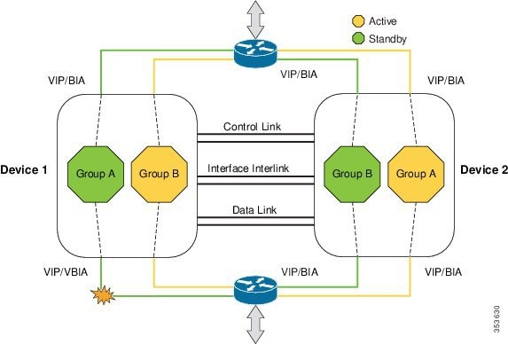
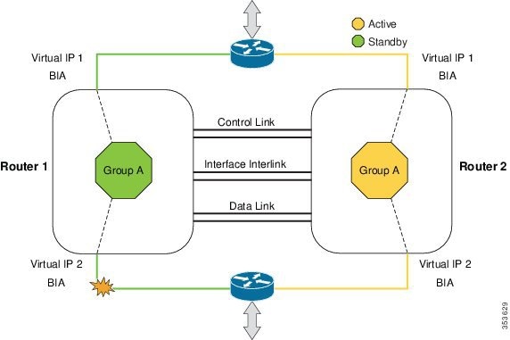
You can configure pairs of routers to act as hot standbys for each other. This redundancy is configured on an interface basis. Pairs of redundant interfaces are known as redundancy groups. The figure below depicts the active-standby device scenario. It shows how the redundancy group is configured for a pair of routers that has one outgoing interface. The Redundancy Group Configuration—Two Outgoing Interfaces figure depicts the active-active device scenario shows how two redundancy groups are configured for a pair of routers that have two outgoing interfaces.
Note that in both cases, the redundant routers are joined by a configurable control link and a data synchronization link. The control link is used to communicate the status of the routers. The data synchronization link is used to transfer stateful information from Network Address Translation (NAT) and the firewall and to synchronize the stateful database for these applications.
Also, in both cases, the pairs of redundant interfaces are configured with the same unique ID number known as the RII.
The following scenarios are examples of Box-to-Box High Availability deployment for Cisco CSR1000v routers:
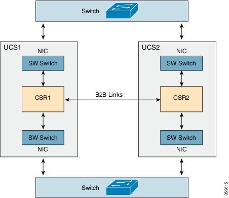
In this deployment, two redundant Cisco CSR 1000v routers are in two independent UCS servers. The two Cisco Unified Computing System (UCS) servers can be in the same data center or two different data centers in different regions. We recommended that you configure two individual physical connections for box-to-box high availability data and control links. However, if the two dedicated physical links are not available, the box-to-box high availability data and control traffic can go through different LAN extension connections. Box-to-Box high availability parameters, such as heart beat period need to be adjusted to take into account the extended delay.
LAN interfaces of each Cisco CSR 1000v router are connected with UCS physical network interface card (NIC) interfaces through switches (for example, ESXi L2 SW). The two physical NICs on each UCS are connected to outside switch to form a box-to-box pair. Gratuitous Address Resolution Protocols (ARP) is sent from CSR LAN interfaces to reach physical switch and its Built-in Address (BIA).
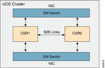
In the above deployment, NAT and Zone-Based Firewall (ZBFW) box-to-box high availability also works on UCS cluster setup. In this case, box-to-box control and data links go through virtual connections within the cluster. Switches (For example, ESXi L2 SW) are used to connect the 2 redundant Cisco CSR 1000v routers to form a box-to-box high availability pair; LAN interfaces on two Cisco CSR 1000v routers are connected directly to the SW switches, and two physical NICs of the cluster UCS are connected with the SW switches to communicate outside the network.
Refer to the Configuring Firewall Stateful Interchassis Redundancy module for additional information on configurations and examples.
Example: Configuring Firewall Box-to-Box High Availability for Cisco CSR1000v Routers
The following examples shows how to configure a redundancy application group, a redundancy group protocol, Virtual IP Address and Redundant Interface Identifier, and control and data interfaces:
!Configures a redundancy application group
Device# configure terminal
Device(config)# redundancy
Device(config-red)# application redundancy
Device(config-red-app)# group 1
Device(config-red-app-grp)# name group1
Device(config-red-app-grp)# priority 100 failover-threshold 50
Device(config-red-app-grp)# preempt
Device(config-red-app-grp)# track 200 decrement 200
Device(config-red-app-grp)# exit

!Configures a redundancy group protocol
Device(config-red-app)# protocol 1
Device(config-red-app-prtcl)# timers hellotime 3 holdtime 9
Device(config-red-app-prtcl)# authentication md5 key-string 0 n1 timeout 100
Device(config-red-app-prtcl)# bfd
Device(config-red-app-prtcl)# end

! Configures a Virtual IP Address and Redundant Interface Identifier
Device# configure terminal
Device(config)# interface GigabitEthernet0/1/1
Device(conf-if)# redundancy rii 600
Device(config-if)# redundancy group 2 ip 10.2.3.4 exclusive decrement 200
Device(config)# redundancy
Device(config-red-app-grp)# data GigabitEthernet0/0/0
Device(config-red-app-grp)# control GigabitEthernet0/0/2 protocol 1
Device(config-red-app-grp)# end

!Configures control and data interfaces
Device# configure terminal
Device(config-red)# application redundancy
Device(config-red-app-grp)# group 1
Device(config-red-app-grp)# data GigabitEthernet 0/0/0
Device(config-red-app-grp)# control GigabitEthernet 0/0/2 protocol 1
Device(config-red-app-grp)# end
Additional References for Firewall Box-to-Box High Availability for Cisco CSR1000v Routers
Related Documents
|
Related Topic |
Document Title |
|---|---|
|
Cisco IOS commands |
|
|
Security commands |
|
|
Firewall Stateful Interchassis Redundancy |
|
Technical Assistance
|
Description |
Link |
|---|---|
|
The Cisco Support and Documentation website provides online resources to download documentation, software, and tools. Use these resources to install and configure the software and to troubleshoot and resolve technical issues with Cisco products and technologies. Access to most tools on the Cisco Support and Documentation website requires a Cisco.com user ID and password. |
Feature Information for Firewall Box-to-Box High Availability for Cisco CSR1000v Routers
The following table provides release information about the feature or features described in this module. This table lists only the software release that introduced support for a given feature in a given software release train. Unless noted otherwise, subsequent releases of that software release train also support that feature.
Use Cisco Feature Navigator to find information about platform support and Cisco software image support. To access Cisco Feature Navigator, go to www.cisco.com/go/cfn. An account on Cisco.com is not required.|
Feature Name |
Releases |
Feature Information |
|---|---|---|
|
Firewall Box-to-Box High Availability for Cisco CSR1000v Routers |
Cisco IOS XE Release 3.14S |
The Firewall Box-to-Box High Availability for Cisco CSR1000v Routers feature enables you to configure pairs of Cisco CSR1000v routers to act a backups for each other. |
 Feedback