IP Addressing: IPv4 Addressing Configuration Guide, Cisco IOS XE Release 3S
Bias-Free Language
The documentation set for this product strives to use bias-free language. For the purposes of this documentation set, bias-free is defined as language that does not imply discrimination based on age, disability, gender, racial identity, ethnic identity, sexual orientation, socioeconomic status, and intersectionality. Exceptions may be present in the documentation due to language that is hardcoded in the user interfaces of the product software, language used based on RFP documentation, or language that is used by a referenced third-party product. Learn more about how Cisco is using Inclusive Language.
- Updated:
- August 2, 2013
Chapter: Auto-IP
Auto-IP
 Note |
A device in a ring is called a node. |
- Finding Feature Information
- Prerequisites for Auto-IP
- Restrictions for Auto-IP
- Information About Auto-IP
- How to Configure Auto-IP
- Configuration Examples for Auto-IP
- Additional References for Auto-IP
- Feature Information for Auto-IP
Finding Feature Information
Your software release may not support all the features documented in this module. For the latest caveats and feature information, see Bug Search Tool and the release notes for your platform and software release. To find information about the features documented in this module, and to see a list of the releases in which each feature is supported, see the feature information table at the end of this module.
Use Cisco Feature Navigator to find information about platform support and Cisco software image support. To access Cisco Feature Navigator, go to www.cisco.com/go/cfn. An account on Cisco.com is not required.
Prerequisites for Auto-IP
Restrictions for Auto-IP
- Auto-IP addresses should contain an odd number in the last octet (such as 10.1.1.1, where the number in the last octet is 1).
- The auto-IP feature is not supported on a virtual routing and forwarding (VRF). Auto-IP address configuration must not be configured on an interface which belongs to a VRF other than the global or default VRF.
Information About Auto-IP
- Auto-IP
- Seed Device
- Auto-IP Configuration for Inserting a Device into an Auto-IP Ring
- Device Removal from an Auto-IP Ring
- Conflict Resolution using the Auto-Swap Technique
Auto-IP
The Auto-IP feature is an enhancement of Link Layer Discovery Protocol (LLDP). LLDP supports a set of attributes that it uses to discover neighbor devices. These attributes contain type, length, and value descriptions, and are referred to as a Type Length Value (TLV).
In a ring topology, 2 network-to-network interfaces (NNIs or node interfaces) of a device are used to be part of a ring. The auto-IP feature is an automatic method to provide IP addresses to the node interfaces inserted into a ring. One node interface is designated as the ‘owner’ interface and the other as the ‘non-owner’ interface.
For a ring to function as an auto-IP ring, you must enable the auto-IP functionality on all the node interfaces within a ring.
Note |
The 2 node interfaces which are designated to be part of a ring must be configured with the same auto-IP address. |
Before insertion, the interfaces are not designated as ‘owner’ and ‘non-owner’. After insertion, the auto-IP TLV is exchanged between the neighbor devices. During this initial negotiation with the adjacent device interfaces, ‘owner’ and ‘non-owner’ interfaces are determined automatically.
Note |
Auto-IP address is used for allocation purposes only and not used as an IP address for a node interface until the IP address is configured on an interface. |
After a device is inserted into a ring, the auto-IP address configured for the device (such as 10.1.1.1) is assigned to the owner interface for the '/31' subnet. An owner interface has a priority 2 in the auto-IP TLV, and a non-owner interface has priority 0 in the auto-IP TLV. If there is no assigned IP address on the ring interface (before the node is inserted into a ring), then the ring interface has priority 1 in the auto-IP TLV.
The IP negotiation is based on priority; the higher value of priority wins the negotiation. If the priority is equal, then IP negotiation fails. This typically means incorrect configuration or wiring. In such a scenario, you must make sure the configuration and wiring is proper.
Seed Device
A ring must have at least one seed device. To configure a device as a seed device in an auto-IP ring, you must manually configure the IP address configured on one of its node interfaces with the auto-IP address of the interface, with the mask '/31' (or 255.255.255.254).
A sample topology is given below. In this scenario, device R1 is being configured as the seed device.
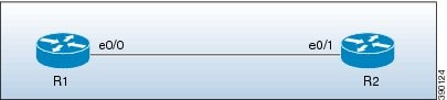
The e0/0 interface on device R1 is configured with the auto-IP address 10.1.1.1 and the e0/1 interface on device R2 is configured with the auto-IP address 10.1.1.3.
To configure R1 as the seed device, the same IP address must be configured as the auto-IP address and the IP address of the interface e0/0. By configuring the IP address of e0/0 interface of R1 to its auto-IP address, R1 becomes the seed device and the interface e0/0 becomes the owner of the subnet.
The process of configuring the device R1 as the seed device is given below:
After a connection is established between the devices R1 and R2, R1 sends a Link Layer Discovery Protocol(LLDP) packet which contains an auto-IP Type Length Value (TLV) with priority 2.
| Interface IP address | Auto-IP address | Priority |
| 10.1.1.1 | 10.1.1.1 | 2 |
On receiving the auto-IP TLV from R1, R2 derives the IP address for the interface e0/1 (by subtracting 1 from the last octet of R1's auto-IP address), and assigns the IP address 10.1.1.0/31 to R2's e0/1 interface. The interface e0/1 on R2 becomes the non-owner interface on this subnet.
The IP address allocation is displayed in the illustration given below:
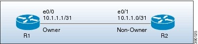
The device and node interface details for the subnet are given below:
| Device | Interface | IP address | Designation |
| R1 | e0/0 | 10.1.1.1/31 | Owner |
| R2 | e0/1 | 10.1.1.0/31 | Non-owner |
Note |
Since the auto-IP address configured on the e0/1 interface on R2 is 10.1.1.3, the other node interface of R2 is designated as the owner interface and 10.1.1.3 is automatically configured as the interface IP address of the other node interface. |
Auto-IP Configuration for Inserting a Device into an Auto-IP Ring
To insert a device into an existing auto-IP ring, the node interfaces of the device must be configured with the auto-IP address.
Note |
You can also enable the auto-IP functionality on node interfaces that are part of an existing, but non-auto-IP ring. |
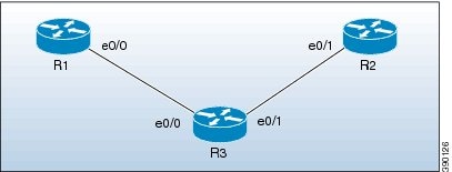
The topology in the illustration below explains the sample scenario.
In the topology above, device R1 is configured as the seed device. Interface e0/0 on R1 is configured with the IP address 10.1.1.1/31, and is the owner of the subnet connecting R1 and R2. Interface e0/1 on device R2 has the IP address 10.1.1.0/31, and is the non-owner interface of the subnet.
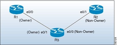
Device R3 is inserted between R1 and R2. The 2 designated node interfaces e0/0 and e0/1 of R3 are configured with the auto-IP address 10.1.1.5. After the insertion, the ring topology looks like this:
- R1 sends an auto-IP Type Length Value (TLV) with priority 2 to the e0/0 interface of R3.
- After receiving the auto-IP TLV from R1, R3 sends an auto-IP TLV with priority 0 to the e0/0 interface of R1.
- R1 wins the election process and the interface e0/0 of R1 is designated as the owner interface on the subnet connecting R1 and R3.
- The e0/0 interface on R3 becomes the non-owner interface and the IP address 10.1.1.0 is assigned to it.
- The other node interface on R3 is designated as an owner interface and its auto-IP address (10.1.1.5) is assigned as the IP address of the interface.
- R3 sends an auto-IP TLV with priority 2 to the e0/1 interface of R2.
- After receiving the auto-IP TLV from R3, R2 sends an auto-IP TLV with priority 0 to the e0/1 interface of R3.
- R3 wins the election process and its interface e0/1 is designated as the owner interface on the subnet connecting R3 and R2.
- The e0/1 interface on R2 is designated as the non-owner interface, and the IP address 10.1.1.4 is assigned to it.
- The other node interface on R2 is designated as the owner interface and its auto-IP address is assigned as the IP address.
The IP addresses that are configured for the owner and non-owner interfaces on the devices R1, R2, and R3 are given below:
| Device | Interface | IP Address | Designation |
| R1 | e0/0 | 10.1.1.1/31 | Owner |
| R3 | e0/0 | 10.1.1.0/31 | Non-owner |
| R3 | e0/1 | 10.1.1.5/31 | Owner |
| R2 | e0/1 | 10.1.1.4/31 | Non-owner |
Device Removal from an Auto-IP Ring
Note |
No configuration is required to remove a device from an auto-IP ring. |
The topology in the illustration below explains the sample scenario:
In the topology, device R3 is removed from the auto-IP ring and device R1 is connected to R2. As a result, auto-IP Type Length Value (TLVs) are exchanged between R1 and R2. Since the e0/0 interface of R1 sends an auto-IP TLV with priority 2 and the e0/1 interface of R2 sends an auto-IP TLV with priority 0 to the e0/0 interface on R1, the e0/0 interface of R1 is designated as the owner interface on the subnet connecting R1 and R2. R1 assigns the IP address to the e0/1 interface on R2, and it becomes the non-owner interface on this subnet.
After the removal of R3 from the auto-IP ring, the ring topology looks like this:
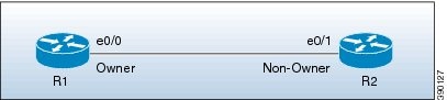
The IP address of the owner and non-owner interfaces on the subnet are given below:
| Device | Interface | Designation |
| R1 | e0/0 | Owner |
| R2 | e0/1 | Non-owner |
Conflict Resolution using the Auto-Swap Technique
If you remove a device from an auto-IP ring, the owner and non-owner auto-IP configuration on the node interfaces is retained. You can insert the device back into an auto-IP ring.
If you incorrectly insert a device into a ring with its interfaces swapped (due to which 2 owner interfaces and 2 non-owner interfaces are connected to each other, rather than a connection between an owner and a non-owner interface), then identical priority values are exchanged between interfaces during the auto-IP Type Length Value (TLV) transmission. Since there is a tie in the priority value that is exchanged between the node interfaces of the inserted device, a conflict is detected.
The 'auto-swap' technique resolves conflicts on both the node interfaces of the inserted device and allows allocation of IP addresses for the interfaces.
Note |
No configuration is required to enable the auto-swap technique; it is enabled automatically. Use the auto-swap technique only when conflict is detected on both the node interfaces of the device. |
The topology in the illustration below explains the sample scenario:
In this topology, device R3 is incorrectly inserted between the devices R1 and R2, with its interfaces swapped. The conflict arises due to incorrect insertion, as given below:
The auto-IP TLV exchange details between R1 and R3 are given below:
Since the same priority value of 2 is sent in both instances, there is a tie during the election process, leading to a conflict.
Similarly, the same priority value of 0 is exchanged between the e0/0 interface of R3 and the e0/1 interface of R2 since they are non-owner interfaces, leading to a conflict.
Auto Swap
The auto-IP feature uses the auto-swap technique to resolve conflicts on both the node interfaces of the inserted device.
The priority and the interface IP address of the e0/1 interface on R3 is swapped with the priority and the interface IP address of the e0/0 interface on R3, respectively.
After swapping, the following auto-IP TLV information is exchanged between R1 and R3:
- The e0/0 interface on R1 sends an auto-IP TLV with priority 2 to the e0/1 interface on R3.
- The e0/1 interface on R3 sends an auto-IP TLV with priority 0 to the e0/0 interface on R1.
Since the priority sent by R1 to R3 is higher than the priority sent by the interface e0/1 on R3, R3 derives the IP address 10.1.1.0 for the e0/1 interface from the auto-IP address of R1 (10.1.1.1).
The following auto-IP TLV information is exchanged between R3 and R2:
- The e0/0 interface on R3 sends an auto-IP TLV with priority 2 to the e0/1 interface on R2.
- The e0/1 interface on R2 sends an auto-IP TLV with priority 0 to the e0/1 interface on R3.
R2 detects the priority sent by R3 to be higher than the priority sent by its interface e0/1 and derives the IP address 10.1.1.4 from the auto-IP address of R3 (10.1.1.5).
After conflict resolution, the topology looks like this:
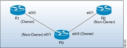
The e0/1 interface on R3 is designated as a non-owner interface and the e0/0 interface on R3 is designated as the owner interface.
How to Configure Auto-IP
- Configuring a Seed Device
- Configuring the Auto-IP Functionality on Node Interfaces (for Inclusion in an Auto-IP Ring)
- Verifying and Troubleshooting Auto-IP
Configuring a Seed Device
You must configure at least one seed device in an auto-IP ring. To configure a seed device, you must configure the auto-IP address on the 2 node interfaces of the device (for a specific ring), and use the same IP address to configure the IP address on one of the 2 node interfaces.
1. enable
2. configure terminal
3. lldp run
4. interface type number
5. auto-ip-ring ring-id ipv4-address auto-ip-address
6. exit
7. interface type number
8. auto-ip-ring ring-id ipv4-address auto-ip-address
9. ip address interface-ip-address subnet-mask
10. end
11. show auto-ip-ring [ring-id][detail]
DETAILED STEPS
Configuring the Auto-IP Functionality on Node Interfaces (for Inclusion in an Auto-IP Ring)
To insert a device into an auto-IP ring or to enable node interfaces in an existing ring, you must configure the auto-IP address on the 2 designated node interfaces of the device.
Perform the steps given below to configure the auto-IP functionality on the 2 node interfaces of a device:
1. enable
2. configure terminal
3. lldp run
4. interface type number
5. auto-ip-ring ring-id ipv4-address auto-ip-address
6. exit
7. interface type number
8. auto-ip-ring ring-id ipv4-address auto-ip-address
9. end
10. show auto-ip-ring [ring-id][detail]
DETAILED STEPS
| Command or Action | Purpose | |
|---|---|---|
| Step 1 | enable Example: Device> enable |
Enables privileged EXEC mode. |
| Step 2 | configure terminal Example: Device# configure terminal |
Enters global configuration mode. |
| Step 3 | lldp run Example: Device(config)# lldp run |
Enables Link Layer Discovery Protocol (LLDP) for the device. |
| Step 4 | interface type number Example: Device(config)# interface ethernet 0/1 |
Specifies an interface type and number, and enters interface configuration mode. |
| Step 5 | auto-ip-ring ring-id ipv4-address auto-ip-address Example: Device(config-if)# auto-ip-ring 4 ipv4-address 10.1.1.3 |
Configures the auto-IP address on the specified interface. |
| Step 6 | exit Example: Device(config-if)# exit |
Exits interface configuration mode and enters global configuration mode. |
| Step 7 | interface type number Example: Device(config)# interface ethernet 1/1 |
Specifies an interface type and number, and enters interface configuration mode. |
| Step 8 | auto-ip-ring ring-id ipv4-address auto-ip-address Example: Device(config-if)# auto-ip-ring 4 ipv4-address 10.1.1.3 |
Configures the auto-IP address on the specified interface. |
| Step 9 | end Example: Device(config-if)# end |
Returns to privileged EXEC mode. |
| Step 10 | show auto-ip-ring [ring-id][detail] Example: Device# show auto-ip-ring 4 detail |
Displays auto-IP information. |
Verifying and Troubleshooting Auto-IP
Perform this task to verify auto-IP functions.
Note |
The commands are not in any specific order. |
1. enable
2. show auto-ip-ring [ring-id][detail]
3. debug auto-ip-ring {ring-id {errors | events} |errors | events}
DETAILED STEPS
| Step 1 |
enable Enables privileged EXEC mode. Example: Device> enable
|
||
| Step 2 |
show auto-ip-ring [ring-id][detail] This command displays auto-IP ring information for a specific device or auto-IP ring. Example:
Device# show auto-ip-ring

Auto-IP ring 1
Auto-IP Address         : 10.1.1.5

Ring Port0              : Ethernet0/0
My Current-IP           : 0.0.0.0
My Priority             : 1

Auto-IP ring 3
Auto-IP Address         : 10.1.1.3

Ring Port0              : Ethernet0/1
My Current-IP           : 0.0.0.0
My Priority             : 1
|
||
| Step 3 |
debug auto-ip-ring {ring-id {errors | events} |errors | events} This command debugs errors and events for the specified auto-IP ring. Example:
Device# debug auto-ip-ring 1 errors

Auto IP Ring errors debugging is on for the ring id : 1
*Jul 26 11:30:40.541: (Ethernet0/0) priority (value:1) conflict detected,  need admin intervention
|
Configuration Examples for Auto-IP
- Example: Configuring a Seed Device
- Example: Configuring the Auto-IP Functionality on Node Interfaces (for Inclusion in an Auto-IP ring)
Example: Configuring a Seed Device
Device> enable
Device# configure terminal
Device(config)# lldp run
Device(config)# interface ethernet 0/0
Device(config-if)# auto-ip-ring 4 ipv4-address 10.1.1.1
Device(config-if)# exit
Device(config)# interface ethernet 1/0
Device(config-if)# auto-ip-ring 4 ipv4-address 10.1.1.1
Device(config-if)# ip address 10.1.1.1 255.255.255.254
Device(config-if)# end
Example: Configuring the Auto-IP Functionality on Node Interfaces (for Inclusion in an Auto-IP ring)
Device> enable
Device# configure terminal
Device(config)# lldp run
Device(config)# interface ethernet 0/1
Device(config-if)# auto-ip-ring 4 ipv4-address 10.1.1.3
Device(config-if)# exit
Device(config)# interface ethernet 1/1
Device(config-if)# auto-ip-ring 4 ipv4-address 10.1.1.3
Device(config-if)# end
Additional References for Auto-IP
Related Documents
| Related Topic |
Document Title |
|---|---|
Configuring IPv4 Addresses |
IP Addressing: IPv4 Addressing Configuration Guide |
| Using Link Layer Discovery Protocol in Multivendor Networks |
Carrier Ethernet Configuration Guide |
| IPv4 Addressing commands |
|
Cisco IOS commands |
Technical Assistance
| Description |
Link |
|---|---|
| The Cisco Support and Documentation website provides online resources to download documentation, software, and tools. Use these resources to install and configure the software and to troubleshoot and resolve technical issues with Cisco products and technologies. Access to most tools on the Cisco Support and Documentation website requires a Cisco.com user ID and password. |
Feature Information for Auto-IP
Feature Name |
Releases |
Feature Information |
|---|---|---|
| Auto-IP |
XE 3.10(S) 15.3(3)S |
The auto-IP feature addresses the problem of manually reconfiguring nodes during insertion, deletion, and movement of nodes within an auto-IP ring. The auto-IP feature automatically provides IP addresses to the node interfaces inserted into an auto-IP ring. The following commands were introduced or modified: auto-ip-ring, debug auto-ip-ring, show auto-ip-ring. |
 Feedback