- Title and copyright: Multichannel DS1/PRI Port Adapter Installation and Configuration
- Preface: Multichannel DS1/PRI Port Adapter Installation and Configuration
- Overview: Multichannel DS1/PRI Port Adapter Installation and Configuration
- Preparing to Install the Multichannel DS1/PRI Port Adapter
- Removing and Installing the Multichannel DS1/PRI Port Adapter
- Configuring the Multichannel DS1/PRI Port Adapter
Multichannel DS1/PRI Port Adapter Installation and Configuration
Bias-Free Language
The documentation set for this product strives to use bias-free language. For the purposes of this documentation set, bias-free is defined as language that does not imply discrimination based on age, disability, gender, racial identity, ethnic identity, sexual orientation, socioeconomic status, and intersectionality. Exceptions may be present in the documentation due to language that is hardcoded in the user interfaces of the product software, language used based on RFP documentation, or language that is used by a referenced third-party product. Learn more about how Cisco is using Inclusive Language.
- Updated:
- September 14, 2007
Chapter: Overview: Multichannel DS1/PRI Port Adapter Installation and Configuration
- Port Adapter Overview
- Multichannel DS1/PRI Overview
- Features
- LEDs
- Cables and Connections
- Port Adapter Locations on the Supported Platforms
- Catalyst RSM/VIP2 Slot Numbering
- Catalyst 6000 Family FlexWAN Module Slot Numbering
- Cisco 7100 Series Routers Slot Numbering
- Cisco 7200 Series Routers and Cisco 7200 VXR Routers Slot Numbering
- Cisco uBR7200 Series Routers Slot Numbering
- Cisco 7201 Router Slot Numbering
- Cisco 7301 Router Slot Numbering
- Cisco 7304 PCI Port Adapter Carrier Card Slot Numbering
- Cisco 7401ASR Router Slot Numbering
- Cisco 7000 Series Routers and Cisco 7500 Series Routers VIP Slot Numbering
- Identifying Interface Addresses
- Catalyst RSM/VIP2 Interface Addresses
- Catalyst 6000 Family FlexWAN Module Interface Addresses
- Cisco 7100 Series Routers Interface Addresses
- Cisco 7200 Series and Cisco 7200 VXR Routers Interface Addresses
- Cisco uBR7200 Series Routers Interface Addresses
- Cisco 7201 Router Interface Addresses
- Cisco 7301 Router Interface Addresses
- Cisco 7304 PCI Port Adapter Carrier Card Interface Addresses
- Cisco 7401ASR Router Interface Addresses
- Cisco 7000 Series Routers and Cisco 7500 Series Routers VIP Interface Addresses
Overview
This chapter describes the multichannel DS1/PRI port adapters and contains the following sections:
•![]() Multichannel DS1/PRI Overview
Multichannel DS1/PRI Overview
•![]() LEDs
LEDs
•![]() Port Adapter Locations on the Supported Platforms
Port Adapter Locations on the Supported Platforms
•![]() Identifying Interface Addresses
Identifying Interface Addresses
Port Adapter Overview
The multichannel DS1/PRI port adapters (PA-MC-2T1, PA-MC-4T1, and PA-MC-8T1) are single-width port adapters that integrate channel service unit (CSU) functionality, data service unit (DSU) functionality, and DS0 channel support into the Cisco router. The PA-MC-8DSX1 integrates DS1 data service unit (DSU) functionality and DS0 channel support into the Cisco router.
The multichannel DS1/PRI port adapter provides two, four, or eight independent T1 (100-ohm) connections using RJ-48C connectors. (See Figure 1-1, Figure 1-2, and Figure 1-3.) Each multichannel DS1/PRI port adapter can provide up to 128 separate, full-duplex, HDLC DS0, fractional, or full T1 channels.

Note ![]() Each port adapter has a handle attached, but this handle is not shown in this publication to allow a full view of the detail on the port adapter faceplate.
Each port adapter has a handle attached, but this handle is not shown in this publication to allow a full view of the detail on the port adapter faceplate.
Figure 1-1 .DS1/PRI Port Adapter Front-Panel View (Two-Port Version Shown)
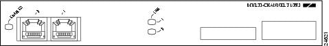
Figure 1-2 DS1/PRI Port Adapter Front-Panel View (Four-Port Version Shown)
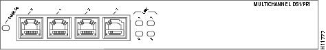
Figure 1-3 DS1/PRI Port Adapter Front-Panel View (Eight-Port Version Shown)
The following table lists the port adapters supported by each platform.
Multichannel DS1/PRI Overview
When you are running channelized T1, each DS1 interface can provide up to 24 T1 channel groups, which are numbered from 0 to 23. Each channel group provides up to twenty-four 64-kbps time slots (DS0 channels), which are numbered 1 to 24. Multiple time slots can be mapped to a single channel group. Each channel group is presented to the system as a serial interface that can be configured individually. Usable bandwidth for each channel group is calculated as n x 56 kbps or n x 64 kbps, where n is a number of DS0 time slots (1 to 24).
Note ![]() The Catalyst 6000 family FlexWAN module does not support ISDN.
The Catalyst 6000 family FlexWAN module does not support ISDN.
When you are running ISDN PRI, each DS1 interface provides 23 bearer (B) channels that can transmit and receive data at the rate of 64 kbps, full-duplex, and one data (D) channel that can transmit and receive data at the rate of 16 kbps, full-duplex. The B channels are used for transmitting user data. The D channel is used for call setup control and network connection teardown, and provides the communication from the router to the ISDN switch. The B and D channels are presented to the system as serial interfaces that support High-Level Data Link Control (HDLC) and Point-to-Point Protocol (PPP) encapsulation. The multichannel DS1/PRI port adapter supports dial-on-demand routing (DDR) when you are running ISDN PRI.
Each of the T1 channels on the multichannel DS1/PRI port adapter uses a portion of the T1 bandwidth (fractional T1) or the entire T1 bandwidth for data transmission. Usable bandwidth for each T1 is n x 64 or n x 56 kbps, where n is a number from 1 to 24. When you are not running at full T1 speeds, the unused portion of the T1 bandwidth cannot be used and is filled with idle channel data.
Note ![]() T1 time slots on the multichannel DS1/PRI port adapter are numbered 1 to 24, instead of the zero-based scheme (0 to 23) used with other Cisco products. This numbering scheme is to ensure consistency with telco numbering schemes for T1 channels within channelized equipment.
T1 time slots on the multichannel DS1/PRI port adapter are numbered 1 to 24, instead of the zero-based scheme (0 to 23) used with other Cisco products. This numbering scheme is to ensure consistency with telco numbering schemes for T1 channels within channelized equipment.
The multichannel DS1/PRI port adapter supports facilities data link (FDL) in Extended Superframe (ESF) framing, as well as network and payload loopbacks. Bit error rate (BER) testing is supported on each of the T1 links. The BER testing is done only over a framed T1 signal and can be run only on one port at a time.
The multichannel DS1/PRI port adapter does not support the aggregation of multiple T1s (called inverse muxing or bonding) for higher bandwidth data rates. The multichannel DS1/PRI port adapter supports Cisco HDLC, Frame Relay, PPP, and Switched Multi megabit Data Service (SMDS) Data Exchange Interface (DXI) encapsulations over each T1 link. For SMDS only, DXI is sent on the T1 line, so it needs to connect to an SMDS switch that has direct DXI input.
Features
The multichannel DS1/PRI port adapter has the following features and physical characteristics:
•![]() Transmits and receives data bidirectionally at the rate of 1.536 Mbps for each T1 port.
Transmits and receives data bidirectionally at the rate of 1.536 Mbps for each T1 port.
•![]() The individual T1 connections on the DSX-1 version of the multichannel DS1/PRI port adapter use 100-ohm RJ-48C cables to connect to external CSUs to a Multi-channel Interface Processor (MIP) or to any other equipment that uses a DSX-1 interface.
The individual T1 connections on the DSX-1 version of the multichannel DS1/PRI port adapter use 100-ohm RJ-48C cables to connect to external CSUs to a Multi-channel Interface Processor (MIP) or to any other equipment that uses a DSX-1 interface.
Note ![]() External DSX-1 channels do not provide CSU functionality and must connect to an external CSU for long-haul applications.
External DSX-1 channels do not provide CSU functionality and must connect to an external CSU for long-haul applications.
•![]() Supports RFC 1406—For information on accessing Cisco MIB files, refer to the Cisco MIB User Quick Reference. For RFC 1406, Cisco supports all tables except the "Frac" table.
Supports RFC 1406—For information on accessing Cisco MIB files, refer to the Cisco MIB User Quick Reference. For RFC 1406, Cisco supports all tables except the "Frac" table.
•![]() For wide-area networking, the multichannel DS1/PRI port adapter can function as a concentrator for a remote site.
For wide-area networking, the multichannel DS1/PRI port adapter can function as a concentrator for a remote site.
Note ![]() The Catalyst RSM/VIP2, Catalyst 6000 family switches, Cisco 7304 PCI Port Adapter Carrier Card, and VIP in Cisco 7000 series routers and Cisco 7500 series routers support online insertion and removal (OIR), but individual port adapters do not. To replace the port adapters, you must first remove the Catalyst RSM/VIP2, Catalyst 6000 family FlexWAN module, Cisco 7304 PCI Port Adapter Carrier Card, or VIP from the chassis and then replace port adapters as required. OIR is supported for port adapters in the Cisco 7100 series routers, Cisco 7200 series routers, Cisco 7200 VXR routers, Cisco uBR7200 series routers, Cisco 7201 router, Cisco 7301 router, and Cisco 7401ASR router.
The Catalyst RSM/VIP2, Catalyst 6000 family switches, Cisco 7304 PCI Port Adapter Carrier Card, and VIP in Cisco 7000 series routers and Cisco 7500 series routers support online insertion and removal (OIR), but individual port adapters do not. To replace the port adapters, you must first remove the Catalyst RSM/VIP2, Catalyst 6000 family FlexWAN module, Cisco 7304 PCI Port Adapter Carrier Card, or VIP from the chassis and then replace port adapters as required. OIR is supported for port adapters in the Cisco 7100 series routers, Cisco 7200 series routers, Cisco 7200 VXR routers, Cisco uBR7200 series routers, Cisco 7201 router, Cisco 7301 router, and Cisco 7401ASR router.
The DS1/PRI line interface unit (LIU) meets the following specifications for input jitter tolerance, pulse shape/amplitude (T1 and DSX1), line termination, and jitter transfer (see Table 1-2):
•![]() ANSI 62411
ANSI 62411
•![]() Bellcore TR499
Bellcore TR499
Table 1-2 provides the T1 channel data rates for the multichannel DS1/PRI port adapter.
|
|
|
|---|---|
0 to 23 |
n x 56 kbps up to full T1 (1.344 Mbps) |
1 Or any mixture of n x 56 and n x 64, where 2n < 24 |
The multichannel DS1/PRI port adapter DS1/PRI ports receive and transmit at the T1 and DSX-1 level while driving and receiving from a 100-ohm shielded twisted-pair cable. This port adapter connects directly to any equipment that has T1 or DSX-1 level input/output. The DS1/PRI front end meets the following specifications:
•![]() Line rate: 1.544 Mbps (± 32 ppm)
Line rate: 1.544 Mbps (± 32 ppm)
•![]() Line code: AMI or B8ZS (bipolar with eight-zero substitution) on the external ports
Line code: AMI or B8ZS (bipolar with eight-zero substitution) on the external ports
•![]() Impedance: 100 ohms
Impedance: 100 ohms
•![]() Pulse shape: ANSI T1.102, pulse amplitude is between 2.4 and 3.6V peak
Pulse shape: ANSI T1.102, pulse amplitude is between 2.4 and 3.6V peak
•![]() Output signal: DSX-1 can drive 655 feet (199.6 meters) of 100-ohm shielded twisted-pair cable and meet DSX-1 pulse shape template at the line side
Output signal: DSX-1 can drive 655 feet (199.6 meters) of 100-ohm shielded twisted-pair cable and meet DSX-1 pulse shape template at the line side
T1 versions of the multichannel DS1/PRI port adapter support all DSX-1 specifications, plus the following features:
•![]() Selectable line build out of 0 dB, -7.5 dB, or -22.5 dB
Selectable line build out of 0 dB, -7.5 dB, or -22.5 dB
•![]() Selectable receiver gain between 26 dB and 36 dB
Selectable receiver gain between 26 dB and 36 dB
•![]() Line protection per UL 1459/1950 and FCC part 68
Line protection per UL 1459/1950 and FCC part 68
Note ![]() Up to 128 interfaces can be configured per multichannel DS1/PRI port adapter. For example, if you have an eight-port multichannel DS1/PRI port adapter with 24 channels per port (or 24 x 8), you have 192 interfaces—this is greater than 128, and therefore is not allowed.
Up to 128 interfaces can be configured per multichannel DS1/PRI port adapter. For example, if you have an eight-port multichannel DS1/PRI port adapter with 24 channels per port (or 24 x 8), you have 192 interfaces—this is greater than 128, and therefore is not allowed.
LEDs
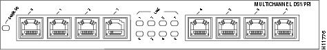
The multichannel DS1/PRI port adapter contains the ENABLED LED, standard on all port adapters, and one status LED for each port. (The LEDs are shown in Figure 1-4, Figure 1-5, and Figure 1-6.)
Figure 1-4 Two-Port Multichannel DS1/PRI Port Adapter LEDs (Horizontal Orientation Shown)
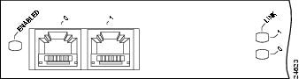
Figure 1-5 Four-Port Multichannel DS1/PRI Port Adapter LEDs (Horizontal Orientation Shown)
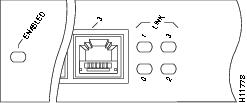
Figure 1-6 Eight-Port Multichannel DS1/PRI Port Adapter LEDs (Horizontal Orientation Shown)
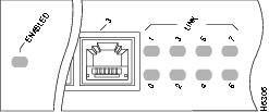
After system initialization, the ENABLED LED goes on, indicating that the multichannel DS1/PRI port adapter has been enabled for operation. The console screen also displays a message as the system discovers each interface during its re initialization.
The following conditions must be met before the multichannel DS1/PRI port adapter is enabled:
•![]() The multichannel DS1/PRI port adapter is correctly connected to the backplane and receiving power.
The multichannel DS1/PRI port adapter is correctly connected to the backplane and receiving power.
•![]() A valid version of multichannel DS1/PRI port adapter microcode is loaded and running.
A valid version of multichannel DS1/PRI port adapter microcode is loaded and running.
•![]() The system bus recognizes the multichannel DS1/PRI port adapter.
The system bus recognizes the multichannel DS1/PRI port adapter.
If any of these conditions are not met, or if the initialization fails for other reasons, the ENABLED LED does not go on.
Table 1-3 lists various system states and functions that are reflected by the front-panel status LEDs on the multichannel DS1/PRI port adapter during the CPU boot process and microcode download.
Note ![]() After the multichannel DS1/PRI port adapter microcode is booted, the microcode takes over control of the LEDs.
After the multichannel DS1/PRI port adapter microcode is booted, the microcode takes over control of the LEDs.
During the system bootup process and microcode download, if an error occurs, the port status LEDs flash yellow a number of times, pause, and then repeat the flashes. Count the number of flashes to determine the error. Table 1-4 lists the LED error indications that might appear.
In all of the preceding error modes, the CPU continually loops and the system does not proceed to the microcode download.
After the system successfully completes the CPU boot process and microcode download, the front-panel port status LEDs on the multichannel DS1/PRI port adapter show the various system states and functions. (See Table 1-5.)
Cables and Connections
The DS1/PRI interface receptacles on the multichannel DS1/PRI port adapter are RJ-48C receptacles for T1 (100-ohm). You can use all interface receptacles simultaneously.
Note ![]() After you properly connect a port to a line, it takes approximately 30 seconds for Cisco IOS software to report that the line is up.
After you properly connect a port to a line, it takes approximately 30 seconds for Cisco IOS software to report that the line is up.
Each connection supports T1 (100-ohm) interfaces that meet T1.403 and ACCUNET TR62411 standards. The RJ-48C connection does not require an external transceiver. The DS1/PRI ports are T1 interfaces that use UTP 100-ohm shielded twisted-pair cables. Figure 1-7 shows the multichannel DS1/PRI port adapter interface cable and connectors.
Note ![]() To meet VCCI Class II EMI requirements, you must use shielded twisted-pair (STP) cables.
To meet VCCI Class II EMI requirements, you must use shielded twisted-pair (STP) cables.
Figure 1-7 DS1/PRI Interface Cable and Connector
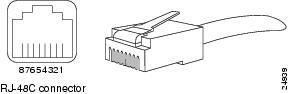
Table 1-6 lists the signal pinouts and descriptions for the RJ-48C connector.
|
|
|
|---|---|
1 |
RX ring |
2 |
RX tip |
3 |
NC |
4 |
TX ring |
5 |
TX tip |
6 |
NC |
7 |
NC |
8 |
NC |
1 TX = transmit. RX= receive. |
Port Adapter Locations on the Supported Platforms
This section discusses port adapter slot locations on the supported platforms. The illustrations that follow summarize slot location conventions on each platform. This section contains the following subsections:
•![]() Catalyst RSM/VIP2 Slot Numbering
Catalyst RSM/VIP2 Slot Numbering
•![]() Catalyst 6000 Family FlexWAN Module Slot Numbering
Catalyst 6000 Family FlexWAN Module Slot Numbering
•![]() Cisco 7100 Series Routers Slot Numbering
Cisco 7100 Series Routers Slot Numbering
•![]() Cisco 7200 Series Routers and Cisco 7200 VXR Routers Slot Numbering
Cisco 7200 Series Routers and Cisco 7200 VXR Routers Slot Numbering
•![]() Cisco uBR7200 Series Routers Slot Numbering
Cisco uBR7200 Series Routers Slot Numbering
•![]() Cisco 7201 Router Slot Numbering
Cisco 7201 Router Slot Numbering
•![]() Cisco 7301 Router Slot Numbering
Cisco 7301 Router Slot Numbering
•![]() Cisco 7304 PCI Port Adapter Carrier Card Slot Numbering
Cisco 7304 PCI Port Adapter Carrier Card Slot Numbering
•![]() Cisco 7401ASR Router Slot Numbering
Cisco 7401ASR Router Slot Numbering
•![]() Cisco 7000 Series Routers and Cisco 7500 Series Routers VIP Slot Numbering
Cisco 7000 Series Routers and Cisco 7500 Series Routers VIP Slot Numbering
Catalyst RSM/VIP2 Slot Numbering
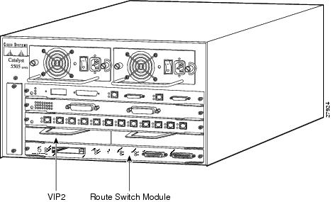
The Catalyst RSM/VIP2 can be installed in any slot in a Catalyst 5000 family switch except the top slots, which contain the supervisor engine modules. The Catalyst RSM/VIP2 does not use interface processor slot numbering; therefore, the slots in which it is installed are not numbered. The multichannel DS1/PRI port adapter can be installed into either port adapter slot 0 or slot 1 on a Catalyst RSM/VIP2. Figure 1-8 shows a Catalyst RSM/VIP2 with two port adapters installed.
Note ![]() The Catalyst 5500 switch has 13 slots. Slot 1 is reserved for the supervisor engine. If a redundant supervisor engine is used, it would go in slot 2; otherwise, slot 2 can be used for other modules. Slot 13 is a dedicated slot, reserved for the ATM switch processor (ASP) module. Refer to the Catalyst 5000 Series Route Switch Module Installation and Configuration Note for any additional slot restrictions for the Catalyst RSM/VIP2.
The Catalyst 5500 switch has 13 slots. Slot 1 is reserved for the supervisor engine. If a redundant supervisor engine is used, it would go in slot 2; otherwise, slot 2 can be used for other modules. Slot 13 is a dedicated slot, reserved for the ATM switch processor (ASP) module. Refer to the Catalyst 5000 Series Route Switch Module Installation and Configuration Note for any additional slot restrictions for the Catalyst RSM/VIP2.
Figure 1-8 Catalyst 5000 Family Switch with Port Adapters Installed on Catalyst RSM/VIP2
Catalyst 6000 Family FlexWAN Module Slot Numbering
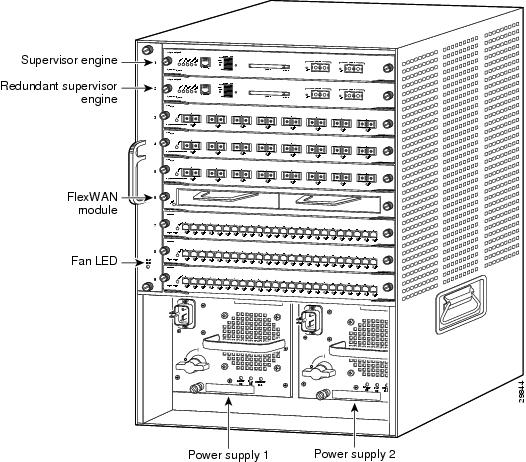
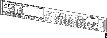
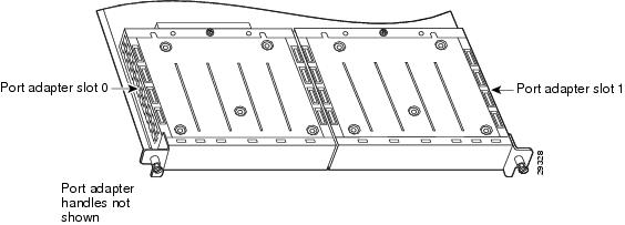
The Catalyst 6000 family FlexWAN module can be installed in any slot in a Catalyst 6000 family switch except slot 1, which is reserved for the supervisor engine. The multichannel DS1/PRI port adapter can be installed into either port adapter bay 0 or bay 1 on a FlexWAN module. Figure 1-9 shows a FlexWAN module with two blank port adapters installed.
Note ![]() Slot 1 is reserved for the supervisor engine. If a redundant supervisor engine is used, it would go in slot 2; otherwise, slot 2 can be used for other modules.
Slot 1 is reserved for the supervisor engine. If a redundant supervisor engine is used, it would go in slot 2; otherwise, slot 2 can be used for other modules.
Figure 1-9 Catalyst 6000 Family Switch with Blank Port Adapters Installed on FlexWAN Module
Cisco 7100 Series Routers Slot Numbering
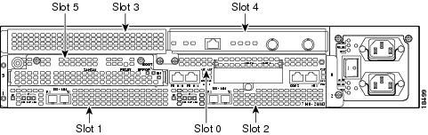
The multichannel DS1/PRI port adapter can be installed in port adapter slot 3 in Cisco 7120 series routers, and in port adapter slot 4 in Cisco 7140 series routers. Figure 1-10 shows the slot numbering on a Cisco 7120 series router. Figure 1-11 shows the slot numbering on a Cisco 7140 series router.
Figure 1-10 Port Adapter Slots in the Cisco 7120 Series Router
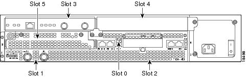
Figure 1-11 Port Adapter Slots in the Cisco 7140 Series Router
Cisco 7200 Series Routers and Cisco 7200 VXR Routers Slot Numbering
Cisco 7202 routers have two port adapter slots. The slots are numbered from left to right. You can place a port adapter in either of the slots (slot 1 or slot 2). The Cisco 7202 router is not shown.
Cisco 7204 routers and Cisco 7204VXR routers have four slots for port adapters, and one slot for an input/output (I/O) controller. The slots are numbered from the lower left to the upper right, beginning with slot 1 and continuing through slot 4. You can place a port adapter in any of the slots (slot 1 through slot 4). Slot 0 is always reserved for the I/O controller. The Cisco 7204 router and Cisco 7204VXR are not shown.
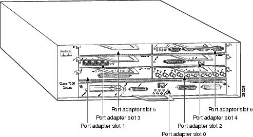
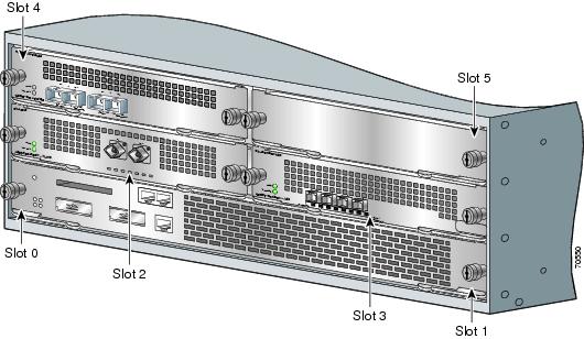
Cisco 7206 routers and Cisco 7206VXR routers (including the Cisco 7206 and Cisco 7206VXR routers as router shelves in a Cisco AS5800 Universal Access Server) have six slots for port adapters, and one slot for an input/output (I/O) controller. The slots are numbered from the lower left to the upper right, beginning with slot 1 and continuing through slot 6. You can place a port adapter in any of the six slots (slot 1 through slot 6). Slot 0 is always reserved for the I/O controller. Figure 1-12 shows the slot numbering on a Cisco 7206 router. The Cisco 7206VXR router is not shown.
Figure 1-12 Port Adapter Slots in the Cisco 7206 Router
Cisco uBR7200 Series Routers Slot Numbering
The Cisco uBR7223 router has one port adapter slot (slot 1). Slot 0 is always reserved for the I/O controller—if present. The Cisco uBR7223 router is not shown.
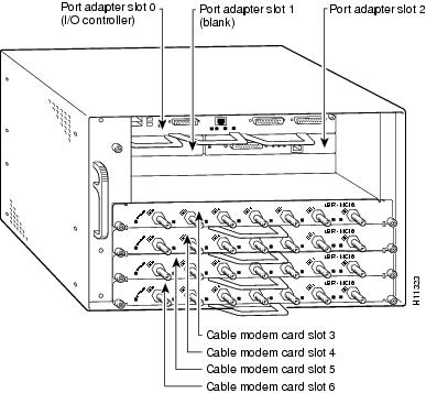
The Cisco uBR7246 router and Cisco uBR7246VXR router have two port adapter slots (slot1 and slot 2). Slot 0 is always reserved for the I/O controller—if present. Figure 1-13 shows the slot numbering of port adapters on a Cisco uBR7246 router or Cisco uBR7246VXR router.
Figure 1-13 Port Adapter Slots in the Cisco uBR7246 Router
Cisco 7201 Router Slot Numbering
Figure 1-14 shows the front view of a Cisco 7201 router with a port adapter installed. There is only one port adapter slot (slot 1) in a Cisco 7201 router.
Figure 1-14 Port Adapter Slot in the Cisco 7201 Router
Cisco 7301 Router Slot Numbering
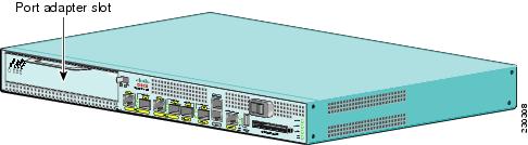
Figure 1-15 shows the front view of a Cisco 7301 router with a port adapter installed. There is only one port adapter slot (slot 1) in a Cisco 7301 router.
Figure 1-15 Port Adapter Slot in the Cisco 7301 Router
Cisco 7304 PCI Port Adapter Carrier Card Slot Numbering
The Cisco 7304 PCI Port Adapter Carrier Card installs in Cisco 7304 router module slots 2 through 5. Figure 1-16 shows a Cisco 7304 PCI Port Adapter Carrier Card with a port adapter installed. The Cisco 7304 PCI Port Adapter Carrier Card accepts one single-width port adapter.
Figure 1-17 shows the module slot numbering on a Cisco 7304 router. The port adapter slot number is the same as the module slot number. Slot 0 and slot 1 are reserved for the NPE module or NSE module.
Figure 1-16 Cisco 7304 PCI Port Adapter Carrier Card—Port Adapter Installed
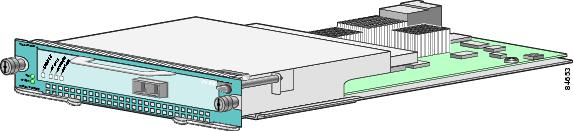
Figure 1-17 Module Slots on the Cisco 7304 Router
Cisco 7401ASR Router Slot Numbering
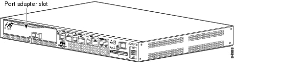
Figure 1-18 shows the front view of a Cisco 7401ASR router with a port adapter installed. There is only one port adapter slot (slot 1) in a Cisco 7401ASR router.
Figure 1-18 Port Adapter Slot in the Cisco 7401ASR Router
Cisco 7000 Series Routers and Cisco 7500 Series Routers VIP Slot Numbering
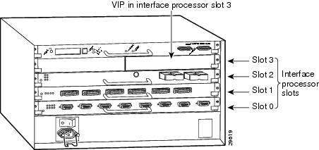
Port adapters are supported on the VIPs (versatile interface processors) used in Cisco 7000 series and Cisco 7500 series routers. In the Cisco 7010 router and Cisco 7505 router, the VIP motherboard is installed horizontally in the VIP slot. In the Cisco 7507 router and Cisco 7513 router, the VIP motherboard is installed vertically in the VIP slot. A port adapter can be installed in either bay (port adapter slot 0 or 1) on the VIP. The bays are numbered from left to right on the VIP. Figure 1-19 shows the slot numbering of a VIP.
Figure 1-19 VIP Slot Locations
Cisco 7010 routers have three slots for port adapters, and two slots for Route Switch Processors (RSPs). The slots are numbered from bottom to top. You can place a port adapter in any of the VIP interface slots (slot 0 through 2). Slots 3 and 4 are always reserved for RSPs. The Cisco 7010 router is not shown.
Cisco 7505 routers have four slots for port adapters, and one slot for an RSP. The slots are numbered from bottom to top. You can place a port adapter in any of the VIP interface slots (slot 0 through 3). One slot is always reserved for the RSP. Figure 1-20 shows the slot numbering on a Cisco 7505 router.
Figure 1-20 VIP Slots in the Cisco 7505 Router
Cisco 7507 routers have five slots for port adapters, and two slots for RSPs. The slots are numbered from left to right. You can place a port adapter in any of the VIP interface slots (slot 0, 1, 4, 5, or 6). Slots 2 and 3 are always reserved for RSPs. The Cisco 7507 router is not shown.
Cisco 7513 routers have eleven slots for port adapters, and two slots for RSPs. The slots are numbered from left to right. You can place a port adapter in any of the VIP interface slots (slots 0 through 5, or slots 9 through 12). Slots 6 and 7 are always reserved for RSPs. The Cisco 7513 router is not shown.
Identifying Interface Addresses
This section describes how to identify interface addresses for the multichannel DS1/PRI port adapter in supported platforms. Interface addresses specify the actual physical location of each interface on a router or switch.
Interfaces on a multichannel DS1/PRI port adapter installed in a router maintain the same address regardless of whether other port adapters are installed or removed. However, when you move a port adapter to a different slot, the first number in the interface address changes to reflect the new port adapter slot number.
Interfaces on a multichannel DS1/PRI port adapter installed in a VIP or FlexWAN module maintain the same address regardless of whether other interface processors or modules are installed or removed. However, when you move a VIP or FlexWAN module to a different slot, the interface processor or module slot number changes to reflect the new interface processor or module slot.
Note ![]() Interface ports are numbered from left to right starting with 0.
Interface ports are numbered from left to right starting with 0.
The following subsections describe the interface address formats for the supported platforms:
•![]() Catalyst RSM/VIP2 Interface Addresses
Catalyst RSM/VIP2 Interface Addresses
•![]() Catalyst 6000 Family FlexWAN Module Interface Addresses
Catalyst 6000 Family FlexWAN Module Interface Addresses
•![]() Cisco 7100 Series Routers Interface Addresses
Cisco 7100 Series Routers Interface Addresses
•![]() Cisco 7200 Series and Cisco 7200 VXR Routers Interface Addresses
Cisco 7200 Series and Cisco 7200 VXR Routers Interface Addresses
•![]() Cisco uBR7200 Series Routers Interface Addresses
Cisco uBR7200 Series Routers Interface Addresses
•![]() Cisco 7201 Router Interface Addresses
Cisco 7201 Router Interface Addresses
•![]() Cisco 7301 Router Interface Addresses
Cisco 7301 Router Interface Addresses
•![]() Cisco 7304 PCI Port Adapter Carrier Card Interface Addresses
Cisco 7304 PCI Port Adapter Carrier Card Interface Addresses
•![]() Cisco 7401ASR Router Interface Addresses
Cisco 7401ASR Router Interface Addresses
•![]() Cisco 7000 Series Routers and Cisco 7500 Series Routers VIP Interface Addresses
Cisco 7000 Series Routers and Cisco 7500 Series Routers VIP Interface Addresses
Table 1-7 summarizes the interface address formats for the supported platforms.
|
|
|
|
|
|---|---|---|---|
Catalyst RSM/VIP2 in Catalyst 5000 family switches |
Port-adapter-slot-number/interface-port-number: channel-group-number |
Port adapter slot— 0 or 1 Interface port1 : • • Channel group—0 through 23 |
0/1:0 |
Catalyst 6000 family FlexWAN module in Catalyst 6000 family switches |
Module-slot-number/port-adapter-bay-number/ interface-port-number:channel-group-number |
Module slot —22 through 13 (depends on the number of slots in the switch) Port adapter bay— 0 or 1 Interface port:3 • • Channel group—0 through 23 |
3/0/0:0 |
Cisco 7120 series router |
Port-adapter-slot-number/interface-port-number: |
Port adapter slot—always 3 Interface port: • • • Channel group—0 through 23 |
3/0:0 |
Cisco 7140 series router |
Port-adapter-slot-number/interface-port-number: |
Port adapter slot—always 4 Interface port: • • • Channel group—0 through 23 |
4/0:0 |
Cisco 7200 series routers and Cisco 7200 VXR routers |
Port-adapter-slot-number/interface-port-number: |
Port adapter slot—0 through 6 (depends on the number of slots in the router)4 Interface port: • • • Channel group—0 through 23 |
1/0:0 |
Cisco 7201 router5 |
Port-adapter-slot-number/interface-port-number: |
Port adapter slot—always 1 Interface port: • • Channel group—0 through 23 |
1/0:0 |
Cisco uBR7223 router |
Port-adapter-slot-number/interface-port-number: |
Port adapter slot—always 14 Interface port: • • • Channel group—0 through 23 |
1/0:0 |
Cisco uBR7246 router |
Port-adapter-slot-number/interface-port-number: |
Port adapter slot—1 or 24 Interface port: • • • Channel group—0 through 23 |
1/2:0 |
Cisco 7301 router6 |
Port-adapter-slot-number/interface-port-number: |
Port adapter slot—always 1 Interface port: • Channel group—0 through 23 |
1/0:0 |
Cisco 7304 PCI Port Adapter Carrier Card in Cisco 7304 router |
Module-slot-number/interface-port-number: |
Module slot—2 through 5 Interface port: • • • Channel group—0 through 23 |
3/0:0 |
Cisco 7401ASR router7 |
Port-adapter-slot-number/interface-port-number: |
Port adapter slot—always 1 Interface port: • Channel group—0 through 23 |
1/0:0 |
VIP in Cisco 7000 series routers or Cisco 7500 series routers |
Interface-processor-slot-number/port-adapter-slot- |
Interface processor slot—0 through 12 (depends on the number of slots in the router) Port adapter slot— 0 or 1 Interface port: • • • Channel group—0 through 23 |
3/1/0:0 |
1 The Catalyst RSM/VIP2 does not support the PA-MC-2T1 multichannel DS1/PRI port adapter. 2 Slot 1 is reserved for the supervisor engine. If a redundant supervisor engine is used, it must go in slot 2; otherwise, slot 2 can be used for other modules. 3 The Catalyst 6000 family FlexWAN module supports the PA-MC-4TI and PA-MC-8T1 multichannel DS1/PRI port adapters only. 4 Port adapter slot 0 is reserved for the Fast Ethernet port on the I/O controller (if present). 5 The Cisco 7201 router supports the PA-MC-2T1 and the PA-MC-4T1 port adapters. 6 The Cisco 7301 router supports the PA-MC-8T1 and the PA-MC-8DSX1 port adapters. 7 The Cisco 7401ASR router supports the PA-MC-8T1 and the PA-MC-8DSX1 port adapters. |
Catalyst RSM/VIP2 Interface Addresses
In Catalyst 5000 family switches, the Catalyst RSM/VIP2 can be installed in any slot except the top slots, which contain the supervisor engine modules. The Catalyst RSM/VIP2 in a Catalyst 5000 family switch does not use interface processor slot numbering; therefore, the slots in which it is installed are not numbered. A port adapter can be installed into either port adapter slot 0 or slot 1 on a Catalyst RSM/VIP2. See Figure 1-8.
The interface address is composed of a three-part number in the format port-adapter-slot number/interface-port number:channel-group-number. See Table 1-7. For example, if a four-port PA-MC-4T1 is installed in port adapter slot 1 of a Catalyst RSM/VIP2 in a Catalyst 5000 family switch, the interface addresses would be 1/0:0, 1/1:0, 1/2:0, 1/3:0 (port adapter slot 1, interface ports 0 through 3, and channel group 0). If an eight-port PA-MC-8T1 or PA-MC-8DSX1 is installed in the same slot, the interface addresses would be 1/0:0, 1/1:0, 1/2:0, 1/3:0, 1/4:0, 1/5:0, 1/6:0, and 1/7:0 (port adapter slot 1 interface ports 0 through 7, and channel group 0).
Catalyst 6000 Family FlexWAN Module Interface Addresses
The Catalyst 6000 family FlexWAN module can be installed in module slots 2 through 9 (depending on the number of slots in the router). Slot 1 is reserved for the supervisor engine. A port adapter can be installed into either port adapter bay 0 or bay 1 on a FlexWAN module. See Figure 1-9.
The interface address is composed of a four-part number in the format module-number/ port-adapter-bay-number/interface-port-number:channel-group-number. See Table 1-7.
The first number identifies the module slot of the chassis in which the FlexWAN module is installed (slot 2 through slot 3, 6, or 9 depending on the number of slots in the chassis). These module slots are generally numbered from top to bottom, starting with 1.
The second number identifies the bay of the FlexWAN module in which the port adapter is installed (0 or 1). The bays are numbered from left to right on the FlexWAN module.
The third number identifies the physical port number on the port adapter. The PA-MC-4T1 is a four-port port adapter, therefore the port number can be 0 through 3. The PA-MC-8T1 is an eight-port port adapter, therefore the port can be 0 through 7.
The fourth number identifies the logical channel group and is a number from 0 through 23.
For example, if a four-port PA-MC-4T1 is installed in the FlexWAN module in module slot 3, port adapter bay 0, the interface addresses would be 3/0:0, 3/1:0, 3/2:0, 3/3:0 (module slot 3, port adapter bay 0, interface ports 0 through 3, and channel group 0). If an eight-port PA-MC-8T1 is installed in the FlexWAN module in module slot 3, port adapter bay 0, the interface addresses would be 3/0/0:0 through 3/0/7:0 (module slot 3, port adapter bay 0, interface ports 0 through 7, and channel group 0).
Note ![]() The FlexWAN module physical port address begins with slot 0, which differs from the conventional Catalyst 6000 family port address, which begins with slot 1.
The FlexWAN module physical port address begins with slot 0, which differs from the conventional Catalyst 6000 family port address, which begins with slot 1.
Cisco 7100 Series Routers Interface Addresses
In Cisco 7120 series router, port adapters are installed in port adapter slot 3. See Figure 1-10. In the Cisco 7140 series router, port adapters are installed in port adapter slot 4. See Figure 1-11.
The interface address is composed of a three-part number in the format port-adapter-slot-number/interface-port-number:channel-group-number. See Table 1-7. For example, if a dual-port PA-MC-2T1 is installed on a Cisco 7120 router, the interface addresses would be 3/0:0 and 3/1:0. If a dual-port PA-MC-2T1 is installed on a Cisco 7140 router, the interface addresses would be 4/0:0 and 4/1:0.
Cisco 7200 Series and Cisco 7200 VXR Routers Interface Addresses
In Cisco 7200 series routers and Cisco 7200 VXR routers, port adapter slots are numbered from the lower left to the upper right, beginning with slot 1 and continuing through slot 2 for the Cisco 7202, slot 4 for the Cisco 7204 and Cisco 7204VXR, and slot 6 for the Cisco 7206 and Cisco 7206VXR. Port adapters can be installed in any available port adapter slot from 1 through 6 (depending on the number of slots in the router). (Slot 0 is reserved for the I/O controller.) See Figure 1-12.
The interface address is composed of a three-part number in the format port-adapter-slot-number/interface-port-number: channel-group-number. See Table 1-7. For example, if a dual-port PA-MC-2T1 is installed in slot 1 on a Cisco 7200 series router, the interface addresses would be 1/0:0 and 1/1:0. If a four-port PA-MC-4T1 is installed in slot 1 on a Cisco 7200 series router, the interface address would be 1/0:0, 1/1:0, 1/2:0, and 1/3:0 (port adapter slot 1 interface ports 0 through 3, and channel group 0). If an eight-port PA-MC-8T1 or PA-MC-8DSX1 is installed in slot 1 on a Cisco 7200 series router, the interface address would be 1/0:0, 1/1:0, 1/2:0, 1/3:0, 1/4:0, 1/5:0, 1/6:0, and 1/7:0 (port adapter slot 1 interface ports 0 through 7, and channel group 0).
Cisco uBR7200 Series Routers Interface Addresses
In the Cisco uBR7223 router, only one slot accepts port adapters and it is numbered slot 1.
In the Cisco uBR7246 router and Cisco uBR7246VXR router, port adapters can be installed in two port adapter slots (slot1 and slot 2). Slot 0 is always reserved for the I/O controller—if present. See Figure 1-13.
The interface address is composed of a three-part number in the format port-adapter-slot-number/interface-port-number: channel-group-number. See Table 1-7. For example, if a dual-port PA-MC-2T1 is installed in slot 1of a Cisco uBR7223 router, the interface addresses would be 1/0:0 and 1/1:0 (port adapter slot 1 interface ports 0 and 1, and channel group 0). If the dual-port PA-MC-2T1 were installed in slot 2 of a Cisco uBR7246 router, the interface addresses would be 2/0:0 and 2/1:0 (port adapter slot 2 interface ports 0 and 1, and channel group 0).
Cisco 7201 Router Interface Addresses
In the Cisco 7201 router, only one slot accepts port adapters and it is numbered as slot 1. See Figure 1-14.
The interface address is composed of a three-part number in the format port-adapter-slot-number/interface-port-number:channel-group-number. See Table 1-7. For example, if a four-port PA-MC-4T1 is installed in a Cisco 7201 router, the interface address would be 1/0:0, 1/1:0, 1/2:0, and 1/3:0 (port adapter slot 1 interface ports 0 through 3, and channel group 0).
Cisco 7301 Router Interface Addresses
In the Cisco 7301 router, only one slot accepts port adapters and it is numbered as slot 1. See Figure 1-15.
The interface address is composed of a three-part number in the format port-adapter-slot-number/interface-port-number:channel-group- number. See Table 1-7. For example, if an eight-port PA-MC-8T1 or PA-MC-8DSX1 is installed in a Cisco 7301 router, the interface address would be 1/0:0, 1/1:0, 1/2:0, 1/3:0, 1/4:0, 1/5:0, 1/6:0, and 1/7:0 (port adapter slot 1 interface ports 0 through 7, and channel group 0).
Cisco 7304 PCI Port Adapter Carrier Card Interface Addresses
In the Cisco 7304 router, port adapters are installed in a Cisco 7304 PCI port adapter carrier card, which installs in Cisco 7304 router module slots 2 through 5. The port adapter slot number is the same as the module slot number. SeeFigure 1-16 and Figure 1-17.
The interface address is composed of a three-part number in the format module-slot-number/interface-port-number:channel-group-number. See Table 1-7. For example, if a dual-port PA-MC-2T1 is installed in the Cisco 7304 PCI port adapter carrier card in Cisco 7304 router module slot 3, the interface addresses would be 3/0:0 and 3/1:0 (port adapter slot 3 interface ports 0 and 1, and channel group 0). If a four-port PA-MC-4T1 is installed in the Cisco 7304 PCI port adapter carrier card in Cisco 7304 router module slot 3, the interface addresses would be 3/0:0, 3/1:0, 3/2:0, and 3/3:0 (port adapter slot 3 interface ports 0 through 3, and channel group 0). If an eight-port PA-MC-8T1 or PA-MC-8DSX1 is installed in the Cisco 7304 PCI port adapter carrier card in Cisco 7304 router module slot 3, the interface addresses would be 3/0:0, 3/1:0, 3/2:0, 3/3:0, 3/4:0, 3/5:0, 3/6:0, and 3/7:0 (port adapter slot 3 interface ports 0 through 7, and channel group 0).
Cisco 7401ASR Router Interface Addresses
In the Cisco 7401ASR router, only one slot accepts port adapters and it is numbered as slot 1. See Figure 1-18.
The interface address is composed of a three-part number in the format port-adapter-slot-number/interface-port-number:channel-group-number. See Table 1-7. For example, if an eight-port PA-MC-8T1 or PA-MC-8DSX1 is installed in a Cisco 7401ASR router, the interface address would be 1/0:0, 1/1:0, 1/2:0, 1/3:0, 1/4:0, 1/5:0, 1/6:0, and 1/7:0 (port adapter slot 1 interface ports 0 through 7, and channel group 0).
Cisco 7000 Series Routers and Cisco 7500 Series Routers VIP Interface Addresses
In Cisco 7000 series routers and Cisco 7500 series routers, port adapters are installed on a versatile interface processor (VIP), which installs in interface processor slots 0 through 12 (depending on the number of slots in the router). The port adapter can be installed in either bay (port adapter slot 0 or 1) on the VIP. See Figure 1-19, and Figure 1-20.
The interface address for the VIP is composed of a four-part number in the format interface-processor-slot-number/port-adapter-slot-number/interface-port- number:channel-group-number. See Table 1-7.
The first number identifies the slot in which the VIP is installed (slot 0 through 12, depending on the number of slots in the router).
The second number identifies the bay (port adapter slot) on the VIP in which the port adapter is installed (0 or 1). The bays are numbered from left to right on the VIP.
The third number identifies the physical port number (interface port number) on the port adapter. The port numbers always begin at 0 and are numbered from left to right. The number of additional ports depends on the number of ports on the port adapter. The PA-MC-2T1 is a dual-port port adapter, therefore the port can be 0 or 1. The PA-MC-4T1 is a four-port port adapter, therefore the port can be 0, through 3. The PA-MC-8T1 and PA-MC-8DSX1 are eight-port port adapters, therefore their port can be 0 through 7.
The fourth number identifies the logical channel group and is a number from 0 through 23.
For example, if a dual-port PA-MC-2T1 is installed in a VIP in interface processor slot 3, port adapter slot 1, the interface addresses would be 3/1/0:0 and 3/1/1:0 (interface processor slot 3, port adapter slot 1, interface ports 0 and 1, and channel group 0). If a four-port PA-MC-4T1 is installed in a VIP in interface processor slot 3, port adapter slot 1, the interface addresses would be 3/1/0:0, 3/1/1:0, 3/1/2:0, and 3/1/3:0 (interface processor slot 3, port adapter slot 1, interface ports 0 through 3, and channel group 0). If an eight-port PA-MC-8T1 or PA-MC-8DSX1 is installed in a VIP in interface processor slot 3, port adapter slot 1, the interface addresses would be 3/1/0:0, 3/1/1:0, 3/1/2:0, 3/1/3:0, 3/1/4:0, 31//5:0, 3/1/6:0, and 3/1/7:0 (interface processor slot 3,port adapter slot 1, interface ports 0 through 7, and channel group 0).
Note ![]() Although the processor slots in the seven-slot Cisco 7000 and Cisco 7507 routers and the thirteen-slot Cisco 7513 and Cisco 7576 routers are vertically oriented and those in the five-slot Cisco 7010 and Cisco 7505 routers are horizontally oriented, all Cisco 7000 series and Cisco 7500 series routers use the same method for slot and port numbering.
Although the processor slots in the seven-slot Cisco 7000 and Cisco 7507 routers and the thirteen-slot Cisco 7513 and Cisco 7576 routers are vertically oriented and those in the five-slot Cisco 7010 and Cisco 7505 routers are horizontally oriented, all Cisco 7000 series and Cisco 7500 series routers use the same method for slot and port numbering.
 Feedback