- Title and copyright: PA-2FE-TX and PA-2FE-FX 2-Port Fast Ethernet Port Adapter Installation and Configuration
- Preface: PA-2FE-TX and PA-2FE-FX 2-Port Fast Ethernet Port Adapter Installation and Configuration
- Overview: PA-2FE-TX and PA-2FE-FX 2-Port Fast Ethernet Port Adapter Installation and Configuration
- Preparing to Install the PA-2FE-TX and PA-2FE-FX 2-Port Fast Ethernet Port Adapter
- Removing and Installing the PA-2FE-TX and PA-2FE-FX 2-Port Fast Ethernet Port Adapter
- Configuring the PA-2FE-TX and PA-2FE-FX 2-Port Fast Ethernet Port Adapter
PA-2FE-TX and PA-2FE-FX 2-Port Fast Ethernet Port Adapter Installation and Configuration
Bias-Free Language
The documentation set for this product strives to use bias-free language. For the purposes of this documentation set, bias-free is defined as language that does not imply discrimination based on age, disability, gender, racial identity, ethnic identity, sexual orientation, socioeconomic status, and intersectionality. Exceptions may be present in the documentation due to language that is hardcoded in the user interfaces of the product software, language used based on RFP documentation, or language that is used by a referenced third-party product. Learn more about how Cisco is using Inclusive Language.
- Updated:
- September 14, 2007
Chapter: Removing and Installing the PA-2FE-TX and PA-2FE-FX 2-Port Fast Ethernet Port Adapter
- Handling Port Adapters
- Online Insertion and Removal
- Warnings and Cautions
- Port Adapter Removal and Installation
- Cisco 7100 Series—Removing and Installing a Port Adapter
- Cisco 7200 Series Routers and Cisco 7200 VXR Routers—Removing and Installing a Port Adapter
- Cisco uBR7200 Series Routers—Removing a Port Adapter
- Cisco uBR7200 Series Routers—Installing a Port Adapter
- Cisco 7201 Router—Removing and Installing a Port Adapter
- Cisco 7301 Router—Removing and Installing a Port Adapter
- Cisco 7304 PCI Port Adapter Carrier Card—Removing and Installing a Port Adapter
- Cisco 7401ASR Router—Removing and Installing a Port Adapter
- Cisco 7500 Series Router VIP—Removing and Installing a Port Adapter
Removing and Installing Port Adapters
This chapter describes how to remove the PA-2FE port adapter from supported platforms and also how to install a new or replacement port adapter. This chapter contains the following sections:
•![]() Port Adapter Removal and Installation
Port Adapter Removal and Installation
•![]() Connecting a PA-2FE RJ-45 or SC Cable
Connecting a PA-2FE RJ-45 or SC Cable
Handling Port Adapters
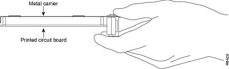
Each port adapter circuit board is mounted to a metal carrier and is sensitive to electrostatic discharge (ESD) damage.

Note ![]() When a port adapter slot is not in use, a blank port adapter must fill the empty slot to allow the router or switch to conform to electromagnetic interference (EMI) emissions requirements and to allow proper airflow across the port adapters. If you plan to install a new port adapter in a slot that is not in use, you must first remove the blank port adapter.
When a port adapter slot is not in use, a blank port adapter must fill the empty slot to allow the router or switch to conform to electromagnetic interference (EMI) emissions requirements and to allow proper airflow across the port adapters. If you plan to install a new port adapter in a slot that is not in use, you must first remove the blank port adapter.

Figure 3-1 Handling a Port Adapter
Online Insertion and Removal
Several platforms support online insertion and removal (OIR) of port adapters; therefore, you do not have to power down routers when removing and replacing a PA-2FE in the Cisco 7100 series routers, Cisco 7200 series routers, Cisco 7200 VXR routers, Cisco uBR7200 series routers, Cisco 7201 router, Cisco 7301 router, or Cisco 7401ASR router.
Although the Cisco 7304 PCI port adapter carrier card and VIP support OIR, individual port adapters do not. To replace port adapters in the Cisco 7304 router or Cisco 7500 series routers, you must first remove the Cisco 7304 PCI port adapter carrier card or VIP from the router and then install or replace port adapters as required. If a blank port adapter is installed in the Cisco 7304 PCI port adapter carrier card or VIP on which you want to install a new port adapter, you must first remove the Cisco 7304 PCI port adapter carrier card or VIP from the router and then remove the blank port adapter.
OIR allows you to install and replace port adapters and service adapters (carrier cards and VIPs) while the router is operating; you do not need to notify the software or shut down the system power, although you should not run traffic through the port adapter you are removing while it is being removed. OIR is a method that is seamless to end users on the network, maintains all routing information, and preserves sessions.
It is wise to gracefully shut down the system before removing a port adapter that has active traffic moving through it. Removing a port adapter while traffic is flowing through the ports can cause system disruption. Once the port adapter is inserted, the ports can be brought back up.
Note ![]() As you disengage the port adapter from the router or switch, OIR administratively shuts down all active interfaces in the port adapter.
As you disengage the port adapter from the router or switch, OIR administratively shuts down all active interfaces in the port adapter.
The following is a functional description of OIR for background information only; for specific procedures for installing and replacing a PA-2FE in a supported platform, refer to the "Port Adapter Removal and Installation" section.
Each PA-2FE has a bus connector that connects it to the router. The connector has a set of tiered pins in three lengths that send specific signals to the system as they make contact with the port adapter. The system assesses the signals it receives and the order in which it receives them to determine if a port adapter is being removed from or introduced to the system. From these signals, the system determines whether to reinitialize a new interface or to shut down a disconnected interface.
Specifically, when you insert a port adapter, the longest pins make contact with the port adapter first, and the shortest pins make contact last. The system recognizes the signals and the sequence in which it receives them.
When you remove or insert a port adapter, the pins send signals to notify the system of changes. The router then performs the following procedure:
1. ![]() Rapidly scans the system for configuration changes.
Rapidly scans the system for configuration changes.
2. ![]() Initializes newly inserted port adapters or administratively shuts down any vacant interfaces.
Initializes newly inserted port adapters or administratively shuts down any vacant interfaces.
3. ![]() Brings all previously configured interfaces on the port adapter back to their previously installed state. Any newly inserted interface is put in the administratively shutdown state, as if it was present (but not configured) at boot time. If a similar port adapter type is reinserted into a slot, its ports are configured and brought online up to the port count of the originally installed port adapter of that type.
Brings all previously configured interfaces on the port adapter back to their previously installed state. Any newly inserted interface is put in the administratively shutdown state, as if it was present (but not configured) at boot time. If a similar port adapter type is reinserted into a slot, its ports are configured and brought online up to the port count of the originally installed port adapter of that type.
Note ![]() Before you begin installation, read "Preparing for Installation," for a list of parts and tools required for installation.
Before you begin installation, read "Preparing for Installation," for a list of parts and tools required for installation.
Warnings and Cautions
Observe the following warnings and cautions when installing or removing port adapters.

Warning ![]() During this procedure, wear grounding wrist straps to avoid ESD damage to the card. Do not directly touch the midplane with your hand or any metal tool, or you could shock yourself. Statement 181
During this procedure, wear grounding wrist straps to avoid ESD damage to the card. Do not directly touch the midplane with your hand or any metal tool, or you could shock yourself. Statement 181
Port Adapter Removal and Installation
In this section, the illustrations that follow give step-by-step instructions on how to remove and install port adapters. This section contains the following illustrations:
•![]() Cisco 7100 Series—Removing and Installing a Port Adapter
Cisco 7100 Series—Removing and Installing a Port Adapter
•![]() Cisco 7200 Series Routers and Cisco 7200 VXR Routers—Removing and Installing a Port Adapter
Cisco 7200 Series Routers and Cisco 7200 VXR Routers—Removing and Installing a Port Adapter
•![]() Cisco uBR7200 Series Routers—Removing a Port Adapter
Cisco uBR7200 Series Routers—Removing a Port Adapter
•![]() Cisco uBR7200 Series Routers—Installing a Port Adapter
Cisco uBR7200 Series Routers—Installing a Port Adapter
•![]() Cisco 7201 Router—Removing and Installing a Port Adapter
Cisco 7201 Router—Removing and Installing a Port Adapter
•![]() Cisco 7301 Router—Removing and Installing a Port Adapter
Cisco 7301 Router—Removing and Installing a Port Adapter
•![]() Cisco 7304 PCI Port Adapter Carrier Card—Removing and Installing a Port Adapter
Cisco 7304 PCI Port Adapter Carrier Card—Removing and Installing a Port Adapter
•![]() Cisco 7401ASR Router—Removing and Installing a Port Adapter
Cisco 7401ASR Router—Removing and Installing a Port Adapter
•![]() Cisco 7500 Series Router VIP—Removing and Installing a Port Adapter
Cisco 7500 Series Router VIP—Removing and Installing a Port Adapter

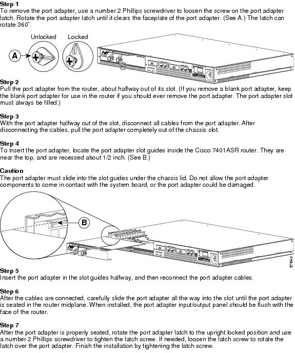
Tip ![]() If a port adapter lever or other retaining mechanism does not move to the locked position, the port adapter is not completely seated in the midplane. Carefully pull the port adapter halfway out of the slot, reinsert it, and move the port adapter lever or other mechanism to the locked position.
If a port adapter lever or other retaining mechanism does not move to the locked position, the port adapter is not completely seated in the midplane. Carefully pull the port adapter halfway out of the slot, reinsert it, and move the port adapter lever or other mechanism to the locked position.
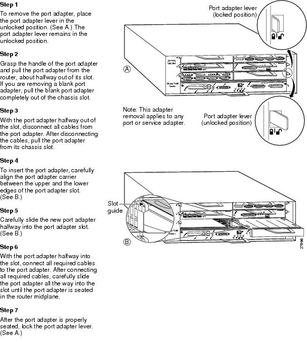
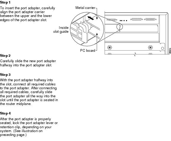
Cisco 7100 Series—Removing and Installing a Port Adapter
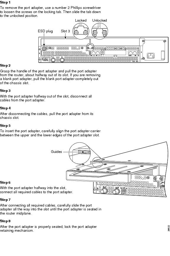
Cisco 7200 Series Routers and Cisco 7200 VXR Routers—Removing and Installing a Port Adapter
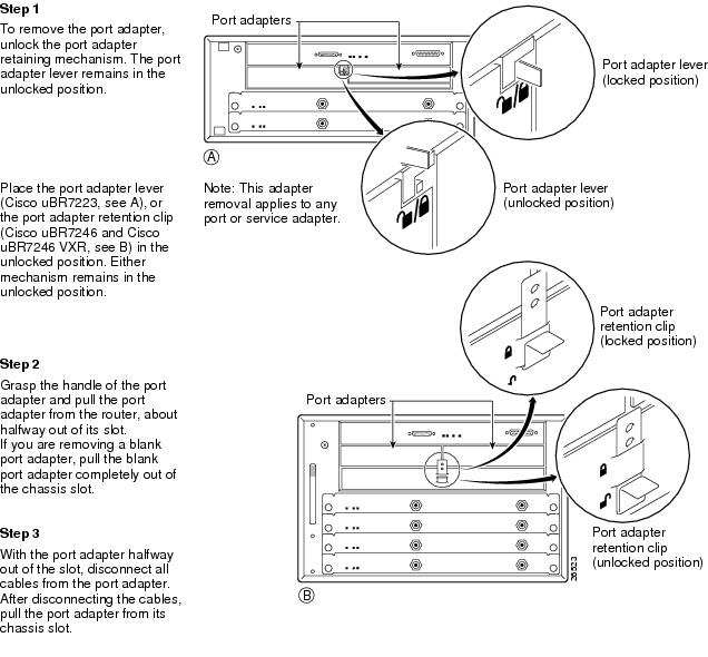
Cisco uBR7200 Series Routers—Removing a Port Adapter
Cisco uBR7200 Series Routers—Installing a Port Adapter
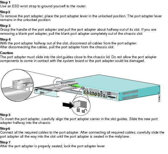
Cisco 7201 Router—Removing and Installing a Port Adapter
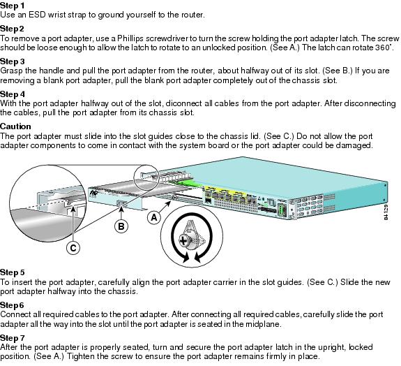
Cisco 7301 Router—Removing and Installing a Port Adapter
Cisco 7304 PCI Port Adapter Carrier Card—Removing and Installing a Port Adapter
You can install one single-width port adapter in a Cisco 7304 PCI port adapter carrier card. This section provides step-by-step instructions for removing and installing a port adapter in a Cisco 7304 PCI port adapter carrier card.
Note ![]() If the Cisco 7304 PCI port adapter carrier card is still in the router, you must remove the port adapter carrier card before removing a port adapter.
If the Cisco 7304 PCI port adapter carrier card is still in the router, you must remove the port adapter carrier card before removing a port adapter.
To remove and install a port adapter in a Cisco 7304 PCI port adapter carrier card, refer to Figure 3-2 and do the following:
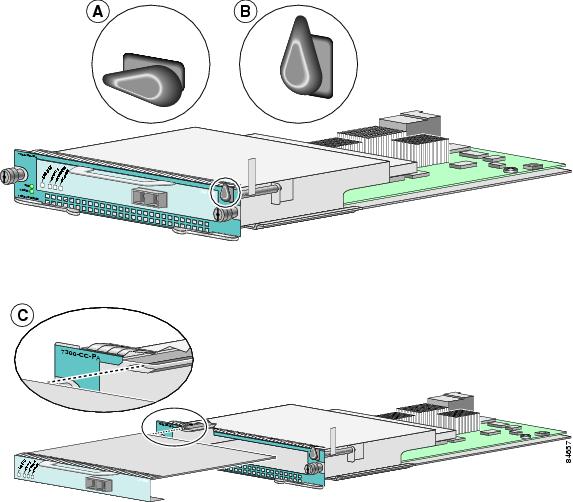
Step 1 ![]() To remove the port adapter from the Cisco 7304 PCI port adapter carrier card, turn the port adapter lock from its locked and horizontal position shown in A of Figure 3-2 to its unlocked and vertical position shown in B of Figure 3-2.
To remove the port adapter from the Cisco 7304 PCI port adapter carrier card, turn the port adapter lock from its locked and horizontal position shown in A of Figure 3-2 to its unlocked and vertical position shown in B of Figure 3-2.
Step 2 ![]() Ensure that the cables are disconnected from the port adapter before removing the Cisco 7304 PCI port adapter carrier card from the chassis.
Ensure that the cables are disconnected from the port adapter before removing the Cisco 7304 PCI port adapter carrier card from the chassis.
Step 3 ![]() Grasp the handle of the port adapter and pull the port adapter from the Cisco 7304 PCI port adapter carrier card.
Grasp the handle of the port adapter and pull the port adapter from the Cisco 7304 PCI port adapter carrier card.
Step 4 ![]() To insert the port adapter in the Cisco 7304 PCI port adapter carrier card, locate the guide rails inside the Cisco 7304 PCI port adapter carrier card that hold the port adapter in place. They are at the top left and top right of the port adapter slot and are recessed about an inch, as shown in C of Figure 3-2.
To insert the port adapter in the Cisco 7304 PCI port adapter carrier card, locate the guide rails inside the Cisco 7304 PCI port adapter carrier card that hold the port adapter in place. They are at the top left and top right of the port adapter slot and are recessed about an inch, as shown in C of Figure 3-2.
Step 5 ![]() Carefully slide the port adapter in the Cisco 7304 PCI port adapter carrier card until the port adapter makes contact with the port adapter interface connector. When fully seated, the port adapter front panel should be flush with the face of the Cisco 7304 PCI port adapter carrier card.
Carefully slide the port adapter in the Cisco 7304 PCI port adapter carrier card until the port adapter makes contact with the port adapter interface connector. When fully seated, the port adapter front panel should be flush with the face of the Cisco 7304 PCI port adapter carrier card.
Step 6 ![]() After the port adapter is properly seated, turn the port adapter lock to its locked and horizontal position, as shown in A of Figure 3-2.
After the port adapter is properly seated, turn the port adapter lock to its locked and horizontal position, as shown in A of Figure 3-2.
Figure 3-2 illustrates how to remove and install a port adapter in a Cisco 7304 PCI port adapter carrier card.
Figure 3-2 Cisco 7304 PCI Port Adapter Carrier Card—Port Adapter Removal and Installation
Cisco 7401ASR Router—Removing and Installing a Port Adapter
Cisco 7500 Series Router VIP—Removing and Installing a Port Adapter
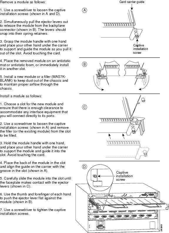
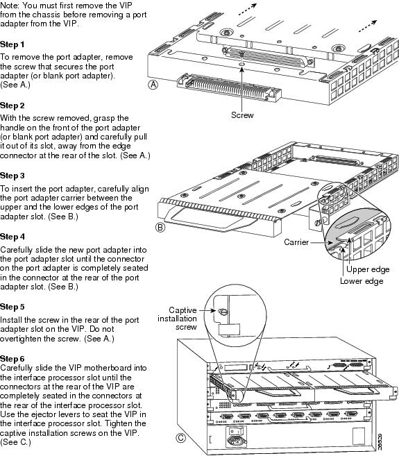
You must remove the versatile interface processor (VIP) from the chassis before removing the port adapter from the VIP or installing the port adapter in the VIP.
Removing and Installing a VIP Carrier Card in the Cisco 7500 Series Router
Removing and Installing the Port Adapter in the VIP Carrier Card
Connecting a PA-2FE RJ-45 or SC Cable
To continue your PA-2FE port adapter installation, you must install the port adapter's interface cables. The following instructions apply to all supported platforms.
RJ-45 and SC-type fiber-optic cables are not available from Cisco; they are available from commercial cable vendors.
Use the following procedure to connect RJ-45 or SC cables:
Step 1 ![]() If you have RJ-45 connections (PA-2FE-TX), attach the Category 5 unshielded twisted-pair (UTP) cable directly to an RJ-45 port on the PA-2FE-TX. (See Figure 3-3.) The PA-2FE is an end-station device and not a repeater. You must connect the PA-2FE to a transceiver, switch, hub, repeater, DTE, or back-to-back to another 10/100-Mbps Fast Ethernet adapter.
If you have RJ-45 connections (PA-2FE-TX), attach the Category 5 unshielded twisted-pair (UTP) cable directly to an RJ-45 port on the PA-2FE-TX. (See Figure 3-3.) The PA-2FE is an end-station device and not a repeater. You must connect the PA-2FE to a transceiver, switch, hub, repeater, DTE, or back-to-back to another 10/100-Mbps Fast Ethernet adapter.
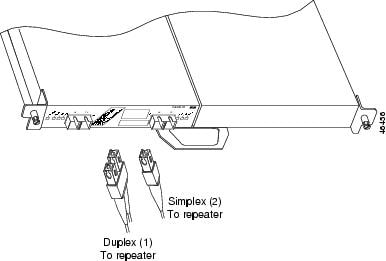
If you have SC connections (PA-2FE-FX), attach the cable directly to an SC port on the PA-2FE-FX. (See Figure 3-4.) Use either one duplex SC connector or two simplex SC connectors, and observe the correct relationship between the receive (RX) and transmit (TX) ports on the PA-2FE-FX and your repeater.
Note ![]() Port adapters have a handle attached, but this handle is not shown to allow a full detailed view of each port adapter's faceplate.
Port adapters have a handle attached, but this handle is not shown to allow a full detailed view of each port adapter's faceplate.
Step 2 ![]() Attach the network end of your RJ-45 or SC-type cable to your 10/100BASE-T transceiver, switch, hub, repeater, DTE, or other external 10/100BASE-T equipment.
Attach the network end of your RJ-45 or SC-type cable to your 10/100BASE-T transceiver, switch, hub, repeater, DTE, or other external 10/100BASE-T equipment.
Figure 3-3 Connecting a PA-2FE-TX RJ-45 Cable—Horizontal Orientation
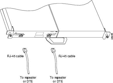
Figure 3-4 Connecting PA-2FE-FX SC Cables—Horizontal Orientation
 Feedback