- Title and copyright: PA-12E/2FE Port Adapter Installation and Configuration
- Preface: PA-12E/2FE Port Adapter Installation and Configuration
- Overview: PA-12E/2FE Port Adapter Installation and Configuration
- Preparing to Install the PA-12E/2FE Port Adapter
- Removing and Installing the PA-12E/2FE Port Adapter
- Configuring the PA-12E/2FE Port Adapter
PA-12E/2FE Port Adapter Installation and Configuration Guide
Bias-Free Language
The documentation set for this product strives to use bias-free language. For the purposes of this documentation set, bias-free is defined as language that does not imply discrimination based on age, disability, gender, racial identity, ethnic identity, sexual orientation, socioeconomic status, and intersectionality. Exceptions may be present in the documentation due to language that is hardcoded in the user interfaces of the product software, language used based on RFP documentation, or language that is used by a referenced third-party product. Learn more about how Cisco is using Inclusive Language.
- Updated:
- September 14, 2007
Chapter: Configuring the PA-12E/2FE Port Adapter
Configuring the PA-12E/2FE
To continue your PA-12E/2FE port adapter installation, you must configure the 12E/2FE interfaces. The instructions that follow apply to all supported platforms. Minor differences between the platforms are noted-with Cisco IOS software commands-are noted.
This chapter contains the following sections:
•![]() Using the EXEC Command Interpreter
Using the EXEC Command Interpreter
•![]() Using the 12E/2FE VLAN Configuration WebTool
Using the 12E/2FE VLAN Configuration WebTool
Using the EXEC Command Interpreter
You modify the configuration of your router through the software command interpreter called the EXEC (also called enable mode). You must enter the privileged level of the EXEC command interpreter with the enable command before you can use the configure command to configure a new interface or change the existing configuration of an interface. The system prompts you for a password if one has been set.
The system prompt for the privileged level ends with a pound sign (#) instead of an angle bracket (>). At the console terminal, use the following procedure to enter the privileged level:
Step 1 ![]() At the user-level EXEC prompt, enter the enable command. The EXEC prompts you for a privileged-level password as follows:
At the user-level EXEC prompt, enter the enable command. The EXEC prompts you for a privileged-level password as follows:
Router> enable
Password:
Step 2 ![]() Enter the password (the password is case sensitive). For security purposes, the password is not displayed.
Enter the password (the password is case sensitive). For security purposes, the password is not displayed.
Step 3 ![]() When you enter the correct password, the system displays the privileged-level system prompt (#):
When you enter the correct password, the system displays the privileged-level system prompt (#):
Router#
To configure the new interfaces, proceed to the "Configuring the Interfaces" section.
Configuring the Interfaces
After you verify that the new PA-12E/2FE is installed correctly (the enabled LED goes on), use the configure command to configure the new interfaces. Be prepared with the information you will need, such as the following:
•![]() Protocols you plan to route on each new interface
Protocols you plan to route on each new interface
•![]() IP addresses, if you will configure the interfaces for IP routing
IP addresses, if you will configure the interfaces for IP routing
•![]() Bridging protocols you plan to use
Bridging protocols you plan to use
If you installed a new PA12E/2FE or if you want to change the configuration of an existing interface, you must enter configuration mode to configure the new interfaces. If you replaced a PA-12E/2FE that was previously configured, the system recognizes the new interfaces and brings each of them up in their existing configuration.
For a summary of the configuration options available and instructions for configuring interfaces on a PA12E/2FE, refer to the appropriate configuration publications listed in the "Related Documentation" section on page vi.
You execute configuration commands from the privileged level of the EXEC command interpreter, which usually requires password access. Contact your system administrator, if necessary, to obtain password access. (See the "Using the EXEC Command Interpreter" section for an explanation of the privileged level of the EXEC.)
This section contains the following subsections:
•![]() Performing a Basic Configuration
Performing a Basic Configuration
•![]() Configuring the Transmission Mode
Configuring the Transmission Mode
Shutting Down an Interface
Before you replace an interface cable, replace port adapters, or remove an interface that you will not replace, use the shutdown command to shut down (disable) the interfaces to prevent anomalies when you reinstall the new or reconfigured interface processor. When you shut down an interface, it is designated administratively down in the show command displays.

Note ![]() Interface port numbers 0 and 1 of the 12E/2FE port adapter are identified by the system as Fast Ethernet interfaces, while interface port numbers 2 through 13 are identified as Ethernet interfaces.
Interface port numbers 0 and 1 of the 12E/2FE port adapter are identified by the system as Fast Ethernet interfaces, while interface port numbers 2 through 13 are identified as Ethernet interfaces.
Follow these steps to shut down an interface:
Step 1 ![]() Enter the privileged level of the EXEC command interpreter (also called enable mode). (See the
Enter the privileged level of the EXEC command interpreter (also called enable mode). (See the
"Using the EXEC Command Interpreter" section for instructions)
Step 2 ![]() At the privileged-level prompt, enter configuration mode and specify that the console terminal will be the source of the configuration commands, as follows:
At the privileged-level prompt, enter configuration mode and specify that the console terminal will be the source of the configuration commands, as follows:
Router# configure terminal
Enter configuration commands, one per line. End with CNTL/Z.
Router(config)#
Step 3 ![]() Shut down interfaces by entering the interface fastethernet (for interface port numbers 0 and 1) or interface ethernet (for interface port numbers 2 through 13) subcommand, and then enter the shutdown command. Table 4-1 shows the command syntax.
Shut down interfaces by entering the interface fastethernet (for interface port numbers 0 and 1) or interface ethernet (for interface port numbers 2 through 13) subcommand, and then enter the shutdown command. Table 4-1 shows the command syntax.
When you have finished, press Ctrl-Z—hold down the Control key while you press Z—or enter end or exit to exit configuration mode and return to the EXEC command interpreter.
Note ![]() If you need to shut down additional interfaces, enter the interface ethernet (for interface port number 0 or 1) or the interface fastethernet (for interface port number 2 through 13) command (followed by the interface address of the interface) for each of the interfaces on your port adapter. Use the no shutdown command to enable the interface.
If you need to shut down additional interfaces, enter the interface ethernet (for interface port number 0 or 1) or the interface fastethernet (for interface port number 2 through 13) command (followed by the interface address of the interface) for each of the interfaces on your port adapter. Use the no shutdown command to enable the interface.
Step 4 ![]() Write the new configuration to NVRAM as follows:
Write the new configuration to NVRAM as follows:
Router# copy running-config startup-config
[OK]
Router#
The system displays an OK message when the configuration has been stored in NVRAM.
Step 5 ![]() Verify that new interfaces are now in the correct state (shut down) using the show interfaces command (followed by the interface type and interface address of the interface) to display the specific interface. Table 4-2 provides examples.
Verify that new interfaces are now in the correct state (shut down) using the show interfaces command (followed by the interface type and interface address of the interface) to display the specific interface. Table 4-2 provides examples.
Step 6 ![]() Reenable interfaces by doing the following:
Reenable interfaces by doing the following:
a. ![]() Repeat Step 3 to reenable and interface. Substitute the no shutdown command for the shutdown command.
Repeat Step 3 to reenable and interface. Substitute the no shutdown command for the shutdown command.
b. ![]() Repeat Step 4 to write the new configuration to memory. Use the copy-running-config startup-config command.
Repeat Step 4 to write the new configuration to memory. Use the copy-running-config startup-config command.
c. ![]() Repeat Step 5 to verify that the interfaces are in the correct state. Use the show interfaces command followed by the interface type and interface address of the interface.
Repeat Step 5 to verify that the interfaces are in the correct state. Use the show interfaces command followed by the interface type and interface address of the interface.
For complete descriptions of software configuration commands, refer to the publications listed in the "Related Documentation" section on page vi.
Performing a Basic Configuration
Following are instructions for a basic configuration: enabling a controller, specifying a bridge group, and specifying IP routing. You might also need to enter other configuration subcommands depending on the requirements for your system configuration and the protocols you plan to route on the interface. For complete descriptions of configuration subcommands and the configuration options available for Ethernet and FastEthernet interfaces, refer to the appropriate software documentation.
Note ![]() If you plan to use a 12E/2FE interface to boot from a network (TFTP) on a Cisco 7200 series router, ensure that the interface is configured for a loop-free environment, an IP address is configured for the interface's bridge-group virtual interface, and system boot image 11.2(10)P, 11.3(2)T, or 11.3(2)AA is installed on your router (use the show version command to view your router's system boot image).
If you plan to use a 12E/2FE interface to boot from a network (TFTP) on a Cisco 7200 series router, ensure that the interface is configured for a loop-free environment, an IP address is configured for the interface's bridge-group virtual interface, and system boot image 11.2(10)P, 11.3(2)T, or 11.3(2)AA is installed on your router (use the show version command to view your router's system boot image).
If you plan to use a 12E/2FE interface to boot from a network (TFTP) on a Cisco uBR7246, ensure that the interface is configured for a loop-free environment, an IP address is configured for the interface's bridge-group virtual interface, and system boot image 12.0(5)T is installed on your router (use the show version command to view your router's system boot image).
Before booting from the network server, use the bridge-group bridge-group number spanning-disabled command to disable the Spanning-Tree Protocol configured on the interface to keep the TFTP server from timing out and closing the connection.
For detailed information about booting from a network (TFTP), loading system images from a network server, and configuring the Spanning-Tree Protocol on your Cisco 7200 series router, refer to the Configuration Fundamentals Configuration Guide and Bridging and IBM Networking Configuration Guide publications. See the "Related Documentation" section on page vi for more information.
In the following procedure, press the Return key after each step unless otherwise noted. At any time you can exit the privileged level and return to the user level by entering disable at the prompt as follows:
Router# disable
Router>
Note ![]() Interface port numbers 0 and 1 of the PA-12E/2FE are identified by the system as Fast Ethernet interfaces, while interface port numbers 2 through 13 are identified as Ethernet interfaces.
Interface port numbers 0 and 1 of the PA-12E/2FE are identified by the system as Fast Ethernet interfaces, while interface port numbers 2 through 13 are identified as Ethernet interfaces.
Step 1 ![]() Enter configuration mode and specify that the console terminal is the source of the configuration subcommands, as follows:
Enter configuration mode and specify that the console terminal is the source of the configuration subcommands, as follows:
Router# configure terminal
Enter configuration commands, one per line. End with CNTL/Z.
Router(config)#
Step 2 ![]() Specify a bridge-group number and Spanning-Tree Protocol by entering the bridge-group command. The following examples are for bridge group 10, 20, and 30, and the IEEE Spanning-Tree Protocol:
Specify a bridge-group number and Spanning-Tree Protocol by entering the bridge-group command. The following examples are for bridge group 10, 20, and 30, and the IEEE Spanning-Tree Protocol:
Router(config)# bridge 10 protocol ieee
Router(config)# bridge 20 protocol ieee
Router(config)# bridge 30 protocol ieee
Router(config)# bridge 40 protocol ieee
Note ![]() The PA-12E/2FE supports up to four bridge groups.
The PA-12E/2FE supports up to four bridge groups.
The PA-12E/2FE port adapter supports DEC and IEEE Spanning-Tree Protocols; however, we recommend using the IEEE protocol when configuring bridge groups.
Step 3 ![]() Specify the first interface to configure by entering the interface fastethernet (for interface port numbers 0 and 1) or interface ethernet (for interface port numbers 2 through 13) subcommand, followed by the interface address of the interface you plan to configure. Table 4-3 provides examples.
Specify the first interface to configure by entering the interface fastethernet (for interface port numbers 0 and 1) or interface ethernet (for interface port numbers 2 through 13) subcommand, followed by the interface address of the interface you plan to configure. Table 4-3 provides examples.
Step 4 ![]() Assign an interface to a bridge group by entering the bridge-group subcommand. Table 4-3 provides examples.
Assign an interface to a bridge group by entering the bridge-group subcommand. Table 4-3 provides examples.
Step 5 ![]() Assign an IP address and subnet mask to the interface (if IP routing is enabled on the system) by using the ip address subcommand, as in the following example:
Assign an IP address and subnet mask to the interface (if IP routing is enabled on the system) by using the ip address subcommand, as in the following example:
Router(config-if)# ip address 10.0.0.0 10.255.255.255
Step 6 ![]() Add any additional configuration subcommands required to enable routing protocols and set the interface characteristics. Table 4-5 provides examples.
Add any additional configuration subcommands required to enable routing protocols and set the interface characteristics. Table 4-5 provides examples.
|
|
|
|
|---|---|---|
Enables integrated routing and bridging on the bridge groups. |
bridge irb |
Router(config)# bridge irb |
Enables a virtual interface on a bridge group and assigns an ip address and subnet mask to the interface. |
interface bvi bridge-group-number ip address |
Router(config-if)#
ip address 10.0.0.0 255.255.255
Router(config-if)# no shutdown Router(config-if) exit |
Specifies the protocol to route in each bridge group. |
bridge bridge-group-number route {ip | ips | appletalk} |
Router(config)# bridge 10 route ips |
Configures an interface for cut-through switching of received and transmitted data.1 |
cut-through [receive | transmit] |
Router(config-if)# cut-through |
Returns an interface to the default; store-and-forward switching. |
no cut-through |
Router(config-if)# no cut-through |
1 The PA-12E/2FE supports store-and-forward or cut-through packet switching technology between interfaces within the same bridge group; store-and-forward is the default. Use the cut-through [receive | transmit] command to configure each interface for cut-through switching of received and transmitted data. To return each interface to store-and-forward switching, use the no cut-through command. |
Step 7 ![]() Reenable the interfaces using the no shutdown command. (See the "Shutting Down an Interface" section.)
Reenable the interfaces using the no shutdown command. (See the "Shutting Down an Interface" section.)
Step 8 ![]() Configure all additional port adapter interfaces as required.
Configure all additional port adapter interfaces as required.
Step 9 ![]() After including all of the configuration subcommands to complete your configuration, press Ctrl-Z-hold down the Control key while you press Z-or enter end or exit to exit configuration mode and return to the EXEC command interpreter prompt.
After including all of the configuration subcommands to complete your configuration, press Ctrl-Z-hold down the Control key while you press Z-or enter end or exit to exit configuration mode and return to the EXEC command interpreter prompt.
Step 10 ![]() Write the new configuration to NVRAM as follows:
Write the new configuration to NVRAM as follows:
Router# copy running-config startup-config
[OK]
Router#
This completes the procedure for creating a basic configuration
Configuring the Transmission Mode
By default, all 12E/2FE interfaces (port 0 through port 13) support autosensing and autonegotiation of the proper transmission mode (half-duplex or full-duplex) with an attached device. If an attached device does not support autosensing and autonegotiation of the proper transmission mode, the 12E/2FE interfaces attached to the device automatically enter half-duplex mode.
Use the show running-config command to determine if a 12E/2FE interface is autosensing and autonegotiating the proper transmission mode with an attached device. If a 12E/2FE interface is autosensing and autonegotiating the transmission mode, the output from the show running-config command does not display transmission mode information. If a 12E/2FE interface is configured for half-duplex or full-duplex mode, the output from the show running-config command displays the configured mode.
The first example below shows that the first 12E/2FE interface port (interface port 0) in port adapter slot 3 is autosensing and autonegotiating the transmission mode with an attached device; the second example shows the same interface configured for half-duplex mode:
Router# show running-config
(display text omitted)
interface FastEthernet3/0
no ip address
bridge-group 1
(display text omitted)
Router# show running-config
(display text omitted)
interface FastEthernet3/0
no ip address
half-duplex
bridge-group 1
(display text omitted)
Use the full-duplex and half-duplex commands to change the transmission mode of a 12E/2FE interface. After changing the transmission mode, use the show interfaces command to verify the interface's transmission mode.
Note ![]() If you use the full-duplex and half-duplex commands to change the transmission mode of the first two 12E/2FE interfaces (port 0 and port 1), the transmission speed of the two 12E/2FE interfaces automatically defaults to 100 Mbps. The first two 12E/2FE interfaces only operate at 10 Mbps when the interfaces are autosensing and autonegotiating the proper connection speed (10 Mbps or 100 Mbps) with an attached device.
If you use the full-duplex and half-duplex commands to change the transmission mode of the first two 12E/2FE interfaces (port 0 and port 1), the transmission speed of the two 12E/2FE interfaces automatically defaults to 100 Mbps. The first two 12E/2FE interfaces only operate at 10 Mbps when the interfaces are autosensing and autonegotiating the proper connection speed (10 Mbps or 100 Mbps) with an attached device.
In the following example, full-duplex mode is configured on the first 12E/2FE interface port (interface port 0) in port adapter slot 3:
Router# configure terminal
Enter configuration commands, one per line. End with CNTL/Z.
Router(config)# interface fastethernet 3/0
Router(config-if)# full-duplex
Router(config-if)# no shutdown
Router(config-if)# exit
Router(config)#
%LINEPROTO-5-UPDOWN: Line protocol on Interface FastEthernet3/0, changed
state to up
%LINK-3-UPDOWN: Interface FastEthernet3/0, changed state to up
Router# show interface fastethernet 3/0
FastEthernet0/0 is administratively up, line protocol is up
(display text omitted)
Full-Duplex, 100BaseTX
(display text omitted)
Use the no full-duplex command to return the interface to autosensing and autonegotiation of the proper transmission mode with the attached device.
In the following example, half-duplex mode is configured on the same 12E/2FE interface port as in the previous example:
Router# configure terminal
Enter configuration commands, one per line. End with CNTL/Z.
Router(config)# interface fastethernet 3/0
Router(config-if)# half-duplex
Router(config-if)# no shutdown
Router(config-if)# exit
Router(config)#
%LINEPROTO-5-UPDOWN: Line protocol on Interface FastEthernet3/0, changed
state to up
%LINK-3-UPDOWN: Interface FastEthernet3/0, changed state to up
Router# show interface fastethernet 3/0
FastEthernet0/0 is administratively up, line protocol is up
(display text omitted)
Half-Duplex, 100BaseTX
(display text omitted)
Use the no half-duplex command to return the interface to autosensing and autonegotiation of the proper transmission mode with the attached device.
Note ![]() For the Cisco 7206 router shelf, the interface specified in the above examples requires a shelf number in the format interface or show interface type shelf number/port adapter slot/interface.
For the Cisco 7206 router shelf, the interface specified in the above examples requires a shelf number in the format interface or show interface type shelf number/port adapter slot/interface.
Checking the Configuration
After configuring the new interface, use the show commands to display the status of the new interface or all interfaces, and use the ping and loopback commands to check connectivity. This section includes the following subsections:
•![]() Using show Commands to Verify the New Interface Status
Using show Commands to Verify the New Interface Status
•![]() Using the ping Command to Verify the Network Connectivity
Using the ping Command to Verify the Network Connectivity
Using show Commands to Verify the New Interface Status
Table 4-6 demonstrates how you can use the show commands to verify that new interfaces are configured and operating correctly and that the PA-12E/2FE appears in them correctly. Sample displays of the output of selected show commands appear in the sections that follow. For complete command descriptions and examples, refer to the publications listed in the "Related Documentation" section on page vi.
Note ![]() The outputs that appear in this document may not match the output you receive when running these commands. The outputs in this document are examples only.
The outputs that appear in this document may not match the output you receive when running these commands. The outputs in this document are examples only.
|
|
|
|
|---|---|---|
show version or show hardware |
Displays system hardware configuration, the number of each interface type installed, Cisco IOS software version, names and sources of configuration files, and boot images |
Router# show version |
show controllers |
Displays all the current interface processors and their interfaces |
Router# show controllers |
show diag slot |
Displays types of port adapters installed in your system and information about a specific port adapter slot, or chassis slot |
Router# show diag 2 |
show interfaces type1 port-adapter-slot-number/ interface-port-number |
Displays status information about a specific type of interface (for example, ethernet) in a Cisco 7200 series router |
Router# show interfaces ethernet 3/4 |
show interfaces type 1/ interface-port number |
Displays status information about a specific type of interface (for example, fastethernet) in a Cisco uBR7246 router |
Router# show interfaces fastethernet 1/1 |
show bridge group |
Displays all bridge groups in the system and their interfaces. |
Router# show bridge group |
show pas eswitch addresses fastethernet (or ethernet port-adapter-slot-number/ interface-port-number |
Displays Layer 2 learned addresses for an interface. |
Router# show pas eswitch addresses fastethernet 3/0 |
show interfaces fastethernet (or ethernet) slot/interface irb |
Displays the routed protocol configured for an interface |
Router# show interfaces fastethernet 1/1 irb |
show protocols |
Displays protocols configured for the entire system and for specific interfaces |
Router# show protocols |
show running-config |
Displays the running configuration file |
Router# show running-config |
show startup-config |
Displays the configuration stored in NVRAM |
Router# show startup-config |
1 On the PA-12E/2FE interface port numbers 0 and 1 are fastethernet interfaces and interface port numbers 2 through 13 are ethernet interfaces. |
If an interface is shut down and you configured it as up, or if the displays indicate that the hardware is not functioning properly, ensure that the interface is properly connected and terminated. If you still have problems bringing up the interface, contact a service representative for assistance. This section includes the following subsections:
•![]() Using the show version or show hardware Commands
Using the show version or show hardware Commands
•![]() Using the show bridge group Command
Using the show bridge group Command
•![]() Using the show interfaces Command
Using the show interfaces Command
Using the show version or show hardware Commands
Display the configuration of the system hardware, the number of each interface type installed, the Cisco IOS software version, the names and sources of configuration files, and the boot images, using the show version (or show hardware) command.
Note ![]() The outputs that appear in this document may not match the output you receive when running these commands. The outputs in this document are examples only.
The outputs that appear in this document may not match the output you receive when running these commands. The outputs in this document are examples only.
Cisco 7200 Series and Cisco uBR7246 Routers
Following is an example of the show version command from a Cisco7206 series router with the P-12E/2FE:
Router# show version
Cisco Internetwork Operating System Software
IOS (tm) 7200 Software (C7200-J-M), Version 11.2(10)p RELEASED SOFTWARE
Copyright (c) 1986-1997 by cisco Systems, Inc.
Compiled Wed 23-Apr-97 15:11 by rmontino
Image text-base: 0x60008890, data-base: 0x608E0000
ROM: System Bootstrap, Version 11.2(10)p RELEASE SOFTWARE
ROM: 7200 Software (C7200-BOOT-M), 11.2(10)p RELEASE SOFTWARE
Router uptime is 4 hours, 22 minutes
System restarted by reload
System image file is "c7200-j-mz", booted via slot0
cisco 7206 (NPE150) processor with 26624K/6144K bytes of memory.
R4700 processor, Implementation 33, Revision 1.0 (Level 2 Cache)
Last reset from power-on
Bridging software.
X.25 software, Version 2.0, NET2, BFE and GOSIP compliant.
TN3270 Emulation software (copyright 1994 by TGV Inc).
Chassis Interface.
32 Ethernet/IEEE 802.3 interface(s)
2 FastEthernet/IEEE 802.3 interface(s)
1024K bytes of packet SRAM memory.
16384K bytes of Flash PCMCIA card at slot 0 (Sector size 128K).
8192K bytes of Flash PCMCIA card at slot 1 (Sector size 128K).
4096K bytes of Flash internal SIMM (Sector size 256K).
Configuration register is 0x0
Using the show diag Command
Display the types of port adapters installed in your system (and specific information about each) using the show diag slot command, where slot is the port adapter slot in a Cisco 7200 series or Cisco uBR7246 router.
Note ![]() The outputs that appear in this document may not match the output you receive when running these commands. The outputs in this document are examples only.
The outputs that appear in this document may not match the output you receive when running these commands. The outputs in this document are examples only.
Cisco 7200 Series and Cisco uBR7246 Routers
Following is an example of the show diag slot command that show a PA-12E/2FE in port adapter slot 3 of a Cisco 7200 series router:
Router# show diag 3
Slot 3:
Ethernet Switch port adapter, 14 ports
Port adapter is analyzed
Port adapter insertion time 20:51:22 ago
Hardware revision 1.0 Board revision AO
Serial number 4294967295 Part number 800-02611-05
Test history 0xFF RMA number 000-000-000
EEPROM format version 255
EEPROM contents (hex):
0x20: FF 3F FF FF FF FF FF FF FF FF FF FF FF FF FF FF
0x30: FF FF FF FF FF FF FF FF FF FF FF FF FF FF FF FF
Using the show bridge group Command
Display all bridge groups in the system and the interfaces configured for each bridge group, using the show bridge group command.
Cisco 7200 Series and Cisco uBR7246 Routers
The following examples are for bridge group 30 and bridge group 40 of a PA-12E/2FE in port adapter slot 3:
Router# show bridge group
Bridge Group 30 is running the IEEE compatible Spanning Tree protocol
Port 19 (FastEthernet3/0) of bridge group 30 is forwarding
Port 20 (FastEthernet3/1) of bridge group 30 is forwarding
Port 21 (Ethernet3/2) of bridge group 30 is forwarding
Port 22 (Ethernet3/3) of bridge group 30 is forwarding
Port 23 (Ethernet3/4) of bridge group 30 is forwarding
Port 24 (Ethernet3/5) of bridge group 30 is forwarding
Port 25 (Ethernet3/6) of bridge group 30 is forwarding
Bridge Group 40 is running the IEEE compatible Spanning Tree protocol
Port 26 (Ethernet3/7) of bridge group 40 is down
Port 27 (Ethernet3/8) of bridge group 40 is down
Port 28 (Ethernet3/9) of bridge group 40 is down
Port 29 (Ethernet3/10) of bridge group 40 is down
Port 30 (Ethernet3/11) of bridge group 40 is down
Port 31 (Ethernet3/12) of bridge group 40 is down
Port 32 (Ethernet3/13) of bridge group 40 is down
Using the show interfaces Command
The show interfaces command displays status information (including the physical slot and interface address) for the interfaces you specify. The example that follows specifies a fastethernet interface.
For complete descriptions of interface subcommands and the configuration options available for Cisco 7200 series and Cisco uBR7246 interfaces, refer to the publications listed in the "Related Documentation" section on page vi.
Note ![]() The outputs that appear in this document may not match the output you receive when running these commands. The outputs in this document are examples only.
The outputs that appear in this document may not match the output you receive when running these commands. The outputs in this document are examples only.
Cisco 7200 Series and Cisco uBR7246 Routers
Following is an example of the show interfaces command used with a Cisco 7200 series router. This example shows all of the information specific to the first 12E/2FE interface port (interface port 0) on a PA-12E/2FE installed in port adapter slot 3:
Router# show interface fastethernet 3/0
FastEthernet3/0 is up, line protocol is up
Hardware is TSWITCH, address is 00e0.f7a4.5130 (bia 00e0.f7a4.5130)
MTU 1500 bytes, BW 100000 Kbit, DLY 100 usec, rely 255/255, load 1/255
Encapsulation ARPA, loopback not set, keepalive set (10 sec)
Half-duplex, 100BaseTX
ARP type: ARPA, ARP Timeout 04:00:00
Last input 00:05:30, output 00:00:00, output hang never
Last clearing of "show interface" counters never
Queueing strategy: fifo
Output queue 0/40, 0 drops; input queue 0/75, 0 drops
5 minute input rate 0 bits/sec, 0 packets/sec
5 minute output rate 0 bits/sec, 0 packets/sec
312 packets input, 18370 bytes, 0 no buffer
Received 216 broadcasts, 0 runts, 0 giants, 0 throttles
3 input errors, 0 CRC, 0 frame, 0 overrun, 3 ignored, 0 abort
0 input packets with dribble condition detected
15490 packets output, 1555780 bytes, 0 underruns
2 output errors, 0 collisions, 2 interface resets
0 babbles, 0 late collision, 0 deferred
0 lost carrier, 0 no carrier
2 output buffer failures, 0 output buffers swapped out
Note ![]() For the Cisco 7206 router shelf, the show interfaces command requires a shelf number in the format show interfaces type-shelf-number/port-adapter-slot/interface.
For the Cisco 7206 router shelf, the show interfaces command requires a shelf number in the format show interfaces type-shelf-number/port-adapter-slot/interface.
Intel Corporation recently changed the specifications for its Peripheral component Interconnect (PCI) Fast Ethernet hardware interface. These changes have been incorporated into certain Cisco hardware products. For most users, this change is transparent. However, an anomaly has been identified when this updated Cisco hardware is used in conjunction with certain releases of Cisco IOS software.
When you enter the show interfaces fastethernet command on a Cisco 7200 series router using Cisco IOS Release 11.1(10) or older, or Release 11.3(4) or older with updated Cisco hardware, the "overrun" field (shown in bold in the output above) is always zero.
If you use this command because you are troubleshooting potential network problems, you may be expecting to see a number in the overrun field.
To work around this problem, issue the following Cisco IOS software command to obtain an overrun value:
Router# show controller fastethernet FE-slot number/0
The following output is normally displayed:
Hardware is DEC21140
dec21140_ds=0x603531A0, registers=0x4D800000, ib=0x300612C0
rx ring entries=64, tx ring entries=128
rxring=0x300613C0, rxr shadow=0x603532C0, rx_head=5, rx_tail=0
txring=0x30061800, txr shadow=0x60353400, tx_head=33, tx_tail=33, tx_count=0
PHY link up
Far End Fault Indication (For Fx Interface): OFF
CSR0=0xFE02E080, CSR3=0x300613C0, CSR4=0x30061800, CSR5=0xFC660000
CSR6=0x320CA002, CSR7=0xFFFFA261, CSR8=0xE0400000, CSR9=0xFFFDC3FF
CSR11=0xFFFE0000, CSR12=0xFFFFFF09, CSR15=0xFFFFFEC8
DEC21140 PCI registers:
bus_no=2, device_no=0
CFID=0x00091011, CFCS=0x22800006, CFRV=0x02000022, CFLT=0x0000FF00
CBIO=0x08312001, CBMA=0x01800000, CFIT=0x28140100, CFDA=0x00000000
MII registers:
Register 0x00: 2000 784F 2000 5C01 0081 0000 0000 0000
Register 0x08: 0000 0000 0000 0000 0000 0000 0000 0000
Register 0x10: 0000 0000 0000 0009 0000 0001 8060
Register 0x18: 8020 0820 0000 3800 A3B9
:
<additional information omitted>
The field that determines overrun is "CSR8" (shown in bold in the output above). This field is in hexadecimal format. To determine an overrun value, take the first four (high-order) digits, drop the first one from the left, convert the remaining three digits to the decimal equivalent, and then divide that number in half.
In the example above, there are overflows recorded in CSR8=0xE0400000. To determine the overflow value from this example, take the first four (high-order) digits (E040), drop the first digit (E), and convert the remaining number (040) to the decimal equivalent (64). Then divide that number in half. The overrun value in this example is 32.
To display the routed protocol configured for an interface, enter the show interfaces fastethernet or ethernet slot/interface irb command. The following example shows that IP is configured for the first 12E/2FE interface in port adapter in slot 3:
Router# show interface fastethernet 3/0 irb
FastEthernet3/0
Routed protocols on FastEthernet3/0:
ip
Bridged protocols on FastEthernet3/0:
appletalk clns decnet ip
vines apollo ipx xns
Software MAC address filter on FastEthernet3/0
Hash Len Address Matches Act Type
0x00: 0 ffff.ffff.ffff 0 RCV Physical broadcast
0x2A: 0 0900.2b01.0001 0 RCV DEC spanning tree
0xC2: 0 0180.c200.0000 0 RCV IEEE spanning tree
0xC7: 0 00e0.f7a4.5130 0 RCV Interface MAC address
0xC7: 1 00e0.f7a4.5130 0 RCV Bridge-group Virtual Interface
Note ![]() For the Cisco 7206 router shelf, the show interfaces irb command requires a shelf number in the format show interfaces type shelf number/port adapter slot/interface irb.
For the Cisco 7206 router shelf, the show interfaces irb command requires a shelf number in the format show interfaces type shelf number/port adapter slot/interface irb.
To display the Layer 2 learned addresses for an interface, enter the show pas eswitch addresses fastethernet or ethernet slot/interface command. The following example shows that the first 12E/2FE interface (listed below as port 0) in port adapter slot 3 has learned the Layer 2 address 00e0.f7a4.5100 for bridge group 30 (listed below as BG 30):
Router# show pas eswitch addresses fastethernet 3/0
U 00e0.f7a4.5100, AgeTs 56273 s, BG 30 (vLAN 0), Port 0
Note ![]() For the Cisco 7206 router shelf, the show pas eswitch addresses fastethernet command requires a shelf number in the format show pas eswitch addresses type-shelf-number/ port-adapter-slot/interface.
For the Cisco 7206 router shelf, the show pas eswitch addresses fastethernet command requires a shelf number in the format show pas eswitch addresses type-shelf-number/ port-adapter-slot/interface.
To determine if a 12E/2FE interface is configured for cut-through packet switching (store-and-forward is the default for all 12E/2FE interfaces), enter the show running-config command. If a 12E/2FE interface is configured for store-and-forward packet switching, output from the show running-config command does not display switching information.
In the following example, the first 12E/2FE interface port (interface port 0) in port adapter slot 3 is configured for cut-through packet switching:
Router# show running-config
(display text omitted)
interface FastEthernet3/0
no ip address
cut-through
bridge-group 1
(display text omitted)
Proceed to the next section, "Using the ping Command to Verify the Network Connectivity," to check network connectivity of the PA-12E/2FE and switch or router.
Using the ping Command to Verify the Network Connectivity
Using the ping command, you can verify that an interface port is functioning properly. This section provides a brief description of this command. Refer to the publications listed in the "Related Documentation" section on page vi, for detailed command descriptions and examples.
The ping command sends echo request packets out to a remote device at an IP address that you specify. After sending an echo request, the system waits a specified time for the remote device to reply. Each echo reply is displayed as an exclamation point (!) on the console terminal; each request that is not returned before the specified timeout is displayed as a period (.). A series of exclamation points (!!!!!) indicates a good connection; a series of periods (.....) or the messages [timed out] or [failed] indicate that a bad connection.
Following is an example of a successful ping command to a remote server with the address 10.0.0.10:
Router# ping 10.0.0.10
Type escape sequence to abort.
Sending 5, 100-byte ICMP Echoes to 10.1.1.10, timeout is 2 seconds:
!!!!!
Success rate is 100 percent (5/5), round-trip min/avg/max = 1/15/64 ms
Router#
If the connection fails, verify that you have the correct IP address for the destination and that the device is active (powered on), and repeat the ping command.
Proceed to the next section "Using loopback Commands," to finish checking network connectivity.
Using loopback Commands
With the loopback test, you can detect and isolate equipment malfunctions by testing the connection between the PA-12E/2FE interface and a remote device such as a modem or a CSU/DSU. The loopback subcommand places an interface in loopback mode, which enables test packets that are generated from the ping command to loop through a remote device or compact serial cable. If the packets complete the loop, the connection is good. If not, you can isolate a fault to the remote device or compact serial cable in the path of the loopback test.
Depending on the mode of the port, issuing the loopback command checks the following path:
•![]() When no compact serial cable is attached to the PA-12E/2FE interface port, or if a DCE cable is attached to a port that is configured as line protocol up, the loopback command tests the path between the network processing engine and the interface port only (without leaving the network processing engine and port adapter).
When no compact serial cable is attached to the PA-12E/2FE interface port, or if a DCE cable is attached to a port that is configured as line protocol up, the loopback command tests the path between the network processing engine and the interface port only (without leaving the network processing engine and port adapter).
•![]() When a DTE cable is attached to the port, the loopback command tests the path between the network processing engine and the near (networking processing engine) side of the DSU or modem to test the PA-12E/2FE interface and compact serial cable.
When a DTE cable is attached to the port, the loopback command tests the path between the network processing engine and the near (networking processing engine) side of the DSU or modem to test the PA-12E/2FE interface and compact serial cable.
Using the 12E/2FE VLAN Configuration WebTool
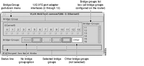
The 12E/2FE VLAN Configuration WebTool, shown in Figure 4-1, is a Web browser-based Java applet that displays configured interfaces and bridge groups for PA-12E/2FE port adapters installed in Cisco 7200 series routers. Using the WebTool, you can:
•![]() Create and delete bridge groups (also referred to as VLANs)
Create and delete bridge groups (also referred to as VLANs)
•![]() Add and remove 12E/2FE interfaces from bridge groups
Add and remove 12E/2FE interfaces from bridge groups
•![]() Assign colors to bridge groups and 12E/2FE interfaces
Assign colors to bridge groups and 12E/2FE interfaces
•![]() Administratively shut down (disable) and bring up (enable) 12E/2FE interfaces
Administratively shut down (disable) and bring up (enable) 12E/2FE interfaces
•![]() View the bridge-group status of each 12E/2FE interface
View the bridge-group status of each 12E/2FE interface
Note ![]() The Cisco 7206 as a router shelf in a Cisco AS5800 Universal Access Server and the Cisco uBR7246 do not support the 12E/2FE VLAN Configuration WebTool.
The Cisco 7206 as a router shelf in a Cisco AS5800 Universal Access Server and the Cisco uBR7246 do not support the 12E/2FE VLAN Configuration WebTool.
This section contains the following subsections:
•![]() Accessing the 12E/2FE VLAN Configuration WebTool
Accessing the 12E/2FE VLAN Configuration WebTool
•![]() Assigning a Color to a New Bridge Group
Assigning a Color to a New Bridge Group
•![]() Adding an Interface to a Bridge Group
Adding an Interface to a Bridge Group
•![]() Removing an Interface From a Bridge Group
Removing an Interface From a Bridge Group
Figure 4-1 12E/2FE VLAN Configuration WebTool
Note ![]() You must use a Java-enabled Web browser to access the 12E/2FE VLAN Configuration WebTool from your router's home page.
You must use a Java-enabled Web browser to access the 12E/2FE VLAN Configuration WebTool from your router's home page.
Accessing the 12E/2FE VLAN Configuration WebTool
All Cisco routers running Cisco IOS Release 11.0 or later have a home page. If your router has an installed PA-12E/2FE, you can access the 12E/2FE VLAN Configuration WebTool from the router's home page.
Note ![]() All Cisco router home pages are password protected. Contact your network administrator if you do not have the name or password for your Cisco 7200 series router.
All Cisco router home pages are password protected. Contact your network administrator if you do not have the name or password for your Cisco 7200 series router.
Follow these steps to access the WebTool from your router's home page:
Step 1 ![]() Enter the name of your router in the URL field of your Web browser and press Return. The browser prompts you for the router password.
Enter the name of your router in the URL field of your Web browser and press Return. The browser prompts you for the router password.
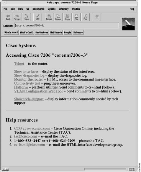
Step 2 ![]() Enter the router password. The browser displays the router's home page. (See Figure 4-2.)
Enter the router password. The browser displays the router's home page. (See Figure 4-2.)
Figure 4-2 Example Home Page for a Cisco 7200 Series Router—Cisco 7206 Shown
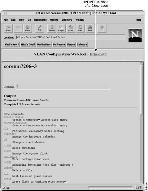
Step 3 ![]() At the home page, select "VLAN Configuration WebTool" in the first list of hypertext links. The browser displays one hypertext link for each PA-12E/2FE installed in the router. (See Figure 4-3.)
At the home page, select "VLAN Configuration WebTool" in the first list of hypertext links. The browser displays one hypertext link for each PA-12E/2FE installed in the router. (See Figure 4-3.)
Note ![]() The VLAN Configuration WebTool hypertext link is listed in the home page only when a PA-12E/2FE is installed in the router.
The VLAN Configuration WebTool hypertext link is listed in the home page only when a PA-12E/2FE is installed in the router.
Figure 4-3 Installed 12E/2FE Port Adapters
Step 4 ![]() Select the hypertext link for an installed PA-12E/2FE. The browser launches the WebTool for the selected PA-12E/2FE. (See Figure 4-1.)
Select the hypertext link for an installed PA-12E/2FE. The browser launches the WebTool for the selected PA-12E/2FE. (See Figure 4-1.)
Note ![]() The browser launches one WebTool for each selected PA-12E/2FE hypertext link. You can launch only one WebTool at a time from the browser.
The browser launches one WebTool for each selected PA-12E/2FE hypertext link. You can launch only one WebTool at a time from the browser.
This completes the procedure for accessing the 12E/2FE VLAN Configuration WebTool.
Creating a Bridge Group
Follow these steps to create a new bridge group:
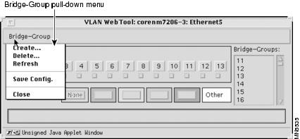
Step 1 ![]() In the WebTool, select the Create option from the Bridge-Group pull-down menu. (See Figure 4-4.)
In the WebTool, select the Create option from the Bridge-Group pull-down menu. (See Figure 4-4.)
The Create New Bridge-Group dialog box appears. (See Figure 4-5.)
Figure 4-4 12E/2FE VLAN Configuration WebTool Pull-Down Menu
Step 2 ![]() In the Create New Bridge-Group dialog box, enter the new bridge-group number and select OK.
In the Create New Bridge-Group dialog box, enter the new bridge-group number and select OK.
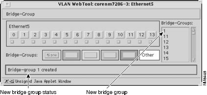
After entering the new bridge-group number and selecting OK, the status line of the WebTool indicates that the new bridge group was created, and the new bridge-group number is listed in the WebTool's configured Bridge-Groups list box. (See Figure 4-6.)
Note ![]() The acceptable range of bridge-group numbers is from 1 to 63. The status line of the WebTool will indicate if the number specified for the new bridge group is already in use or is out of the acceptable range (1-63).
The acceptable range of bridge-group numbers is from 1 to 63. The status line of the WebTool will indicate if the number specified for the new bridge group is already in use or is out of the acceptable range (1-63).
Figure 4-5 Create New-Bridge Group Dialog Box
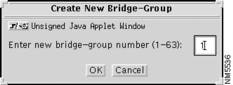
Figure 4-6 Verifying a New Bridge Group
Step 3 ![]() Repeat Step 1 and Step 2 for additional bridge groups.
Repeat Step 1 and Step 2 for additional bridge groups.
Step 4 ![]() Save the change by selecting the Save Config option from the Bridge-Group pull-down menu. (See Figure 4-4.)
Save the change by selecting the Save Config option from the Bridge-Group pull-down menu. (See Figure 4-4.)
This completes the procedure for creating a new bridge group using the 12E/2FE VLAN Configuration WebTool.
Assigning a Color to a New Bridge Group
Using the WebTool you can assign a color to four of the router's configured bridge groups and their 12E/2FE interfaces so that you can easily identify which 12E/2FE interfaces are assigned to a bridge group.
Note ![]() While the configured Bridge-Groups list box displays all bridge groups configured on the router, you can only assign a color to four bridge groups at a time.
While the configured Bridge-Groups list box displays all bridge groups configured on the router, you can only assign a color to four bridge groups at a time.
Follow these steps to assign a color to a new bridge group:
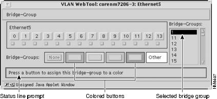
Step 1 ![]() Select the new bridge group from the configured Bridge-Groups list box. The status line of the WebTool prompts you to assign the bridge group to a color. (See Figure 4-7.)
Select the new bridge group from the configured Bridge-Groups list box. The status line of the WebTool prompts you to assign the bridge group to a color. (See Figure 4-7.)
Figure 4-7 Selecting the New Bridge Group
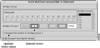
Step 2 ![]() After selecting the bridge group from the Bridge-Groups list box, select one of the Bridge-Groups colored buttons.
After selecting the bridge group from the Bridge-Groups list box, select one of the Bridge-Groups colored buttons.
The bridge group's number is listed in the selected button, the status line of the WebTool indicates that the colored button represents the new bridge group, and the color of the button is applied to the bridge group's 12E/2FE interfaces. (See Figure 4-8.)
Figure 4-8 Assigning a Color to the New Bridge Group
Step 3 ![]() Repeat Step 1 and Step 2 for additional bridge groups.
Repeat Step 1 and Step 2 for additional bridge groups.
This completes the procedure for assigning a color to a new bridge group using the 12E/2FE VLAN Configuration WebTool.
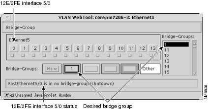
Adding an Interface to a Bridge Group
The following procedure explains how to add a 12E/2FE interface to a bridge group. Before adding a 12E/2FE interface to a bridge group, make sure the desired bridge group is listed in the Bridge-Groups list box and assigned to one of the Bridge-Groups colored buttons. See earlier sections for instructions.
In Figure 4-9, bridge group 1 is listed in the Bridge-Groups list box and is assigned to the first Bridge-Groups colored button.
Note ![]() Placing the cursor over a 12E/2FE interface displays the bridge group and administrative status of the interface in the status line of the WebTool. In Figure 4-9, the first 12E/2FE interface (FastEthernet5/0) is not assigned to a bridge group and is administratively down.
Placing the cursor over a 12E/2FE interface displays the bridge group and administrative status of the interface in the status line of the WebTool. In Figure 4-9, the first 12E/2FE interface (FastEthernet5/0) is not assigned to a bridge group and is administratively down.
Figure 4-9 Selecting an Interface
Step 1 ![]() After verifying that the desired bridge group is listed in the Bridge-Groups list box and assigned to a Bridge-Group button, select the 12E/2FE interface you want to add, and then select the Bridge-Group button.
After verifying that the desired bridge group is listed in the Bridge-Groups list box and assigned to a Bridge-Group button, select the 12E/2FE interface you want to add, and then select the Bridge-Group button.
In Figure 4-10, 12E/2FE interface 5/0 is added to bridge group 1.
Note ![]() To select multiple 12E/2FE interfaces, hold down the Shift key as you select each interface.
To select multiple 12E/2FE interfaces, hold down the Shift key as you select each interface.
Figure 4-10 Verifying an Added Interface
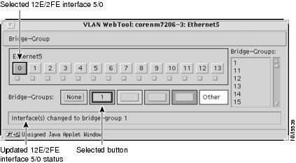
Step 2 ![]() Make sure the status line of the WebTool indicates that the interface was added to the correct bridge group.
Make sure the status line of the WebTool indicates that the interface was added to the correct bridge group.
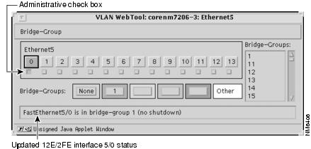
Step 3 ![]() Bring up the interface by selecting the administrative check box below the interface. (See Figure 4-11.)
Bring up the interface by selecting the administrative check box below the interface. (See Figure 4-11.)
Note ![]() To shut down an interface, clear the administrative check box below an interface.
To shut down an interface, clear the administrative check box below an interface.
Figure 4-11 Bringing Up an Interface
Step 4 ![]() Repeat Step 1 through Step 3 for additional interfaces and bridge groups.
Repeat Step 1 through Step 3 for additional interfaces and bridge groups.
Step 5 ![]() Save the change by selecting the Save Config option from the Bridge-Group pull-down menu. (See Figure 4-4.)
Save the change by selecting the Save Config option from the Bridge-Group pull-down menu. (See Figure 4-4.)
This completes the procedure for adding a 12E/2FE interface to a bridge group.
Removing an Interface From a Bridge Group
Follow these steps to remove a 12E/2FE interface from a bridge group:
Step 1 ![]() In the WebTool, select the 12E/2FE interface you want to remove.
In the WebTool, select the 12E/2FE interface you want to remove.
Note ![]() To display the status of a 12E/2FE interface (its assigned bridge-group and administrative state [up or down]) in the status line of the Webtool, place your cursor over the interface.
To display the status of a 12E/2FE interface (its assigned bridge-group and administrative state [up or down]) in the status line of the Webtool, place your cursor over the interface.
Note ![]() To select multiple 12E/2FE interfaces, hold down the Shift key as you select each interface.
To select multiple 12E/2FE interfaces, hold down the Shift key as you select each interface.
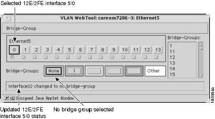
Step 2 ![]() After selecting the 12E/2FE interface you want to remove, select the None option (next to the Bridge-Groups colored buttons). (See Figure 4-12.)
After selecting the 12E/2FE interface you want to remove, select the None option (next to the Bridge-Groups colored buttons). (See Figure 4-12.)
Figure 4-12 Verifying the Removed Interface
Step 3 ![]() Repeat Step 1 and Step 2 for additional interfaces.
Repeat Step 1 and Step 2 for additional interfaces.
Step 4 ![]() Save the change by selecting the Save Config option from the Bridge-Group pull-down menu. (See Figure 4-4.)
Save the change by selecting the Save Config option from the Bridge-Group pull-down menu. (See Figure 4-4.)
This completes the procedure for removing a 12E/2FE interface from a bridge group.
Deleting a Bridge Group
Follow these steps to delete a bridge group:
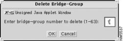
Step 1 ![]() In the WebTool, select the Delete option from the Bridge-Group pull-down menu. (See Figure 4-4.) The Delete Bridge-Group dialog box appears. (See Figure 4-13.)
In the WebTool, select the Delete option from the Bridge-Group pull-down menu. (See Figure 4-4.) The Delete Bridge-Group dialog box appears. (See Figure 4-13.)
Step 2 ![]() In the Delete Bridge-Group dialog box, enter the bridge-group number and select OK.
In the Delete Bridge-Group dialog box, enter the bridge-group number and select OK.
Note ![]() The acceptable range of bridge-group numbers is from 1 to 63.
The acceptable range of bridge-group numbers is from 1 to 63.
Figure 4-13 Delete a Bridge-Group Dialog Box
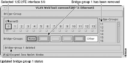
Step 3 ![]() After entering the bridge-group number and selecting OK in the Delete Bridge-Group dialog box, make sure the status line of the WebTool indicates that the bridge group was removed and that the removed bridge group is not listed in the Bridge-Groups list box. (See Figure 4-14.)
After entering the bridge-group number and selecting OK in the Delete Bridge-Group dialog box, make sure the status line of the WebTool indicates that the bridge group was removed and that the removed bridge group is not listed in the Bridge-Groups list box. (See Figure 4-14.)
Note ![]() When you remove a bridge group, all interfaces associated with the removed bridge group are given no bridge group status, the bridge-group number is removed from its assigned color, and the assigned color is removed from the bridge group's interfaces.
When you remove a bridge group, all interfaces associated with the removed bridge group are given no bridge group status, the bridge-group number is removed from its assigned color, and the assigned color is removed from the bridge group's interfaces.
Note ![]() The status line of the WebTool indicates if the number specified for the bridge group you want to remove exists or is out of the acceptable range (1-63).
The status line of the WebTool indicates if the number specified for the bridge group you want to remove exists or is out of the acceptable range (1-63).
Figure 4-14 Verifying a Deleted Bridge Group
Step 4 ![]() Repeat Step 1 through Step 3 for additional bridge groups.
Repeat Step 1 through Step 3 for additional bridge groups.
Step 5 ![]() Save the change by selecting the Save Config option from the Bridge-Group pull-down menu. (See Figure 4-4.)
Save the change by selecting the Save Config option from the Bridge-Group pull-down menu. (See Figure 4-4.)
This completes the procedure for deleting a bridge group.
For additional information about accessing the router home page and using the Cisco Web browser interface, refer to the "Understanding the User Interface" chapter of the Configuration Fundamentals Configuration Guide.
 Feedback