PA-4C-E 1-Port High-Perfomance ESCON Channel Port Adapter Installation and Configuration
Available Languages
Table Of Contents
PA-4C-E 1-Port High-Performance
ESCON Channel Port Adapter Installation and ConfigurationObtaining Documentation, Obtaining Support, and Security Guidelines
Port Adapter Slot Locations on the Supported Platforms
Cisco 7200 Series Routers and Cisco 7200 VXR Routers Slot Numbering
Identifying Interface Addresses
Cisco 7200 Series Routers and Cisco 7200 VXR Routers Interface Addresses
HP ESCON PA Microcode Overview
Hardware and Software Requirements
Cisco 7200 Series Routers and Cisco 7200 VXR Routers Hardware and Software Requirements
Checking Hardware and Software Compatibility
Electrical Equipment Guidelines
Preventing Electrostatic Discharge Damage
Removing and Installing Port Adapters
Port Adapter Removal and Installation
Cisco 7200 Series Routers and Cisco 7200 VXR Routers—Removing and Installing a Port Adapter
Attaching the HP ESCON PA to the Channel
Using the EXEC Command Interpreter
Configuring the HP ESCON PA Interface
Performing a Basic Interface Configuration
Using show Commands to Verify the New Interface Status
Using the Ping Command to Verify Network Connectivity
Upgrading Your HP ESCON PA Microcode
How Does HP ESCON PA Microcode Ship?
Upgrading the HP ESCON PA Microcode from Cisco.com
Configuring the HP ESCON PA Microcode
Copying a New Image to the Flash Memory Card on a Cisco 7200 Series Router
Using Additional Flash Memory Commands
Running HP ESCON PA Diagnostic Tests
PA-4C-E 1-Port High-Performance
ESCON Channel Port Adapter Installation and Configuration
Product Number: PA-4C-E(=)
Platforms Supported: Cisco 7200 Series Routers, including the Cisco 7200 VXR Routers
Document part number: OL-3473-02
Preface
This preface describes the objectives and organization of this document and explains how to find additional information on related products and services. This preface contains the following sections:
•
Obtaining Documentation, Obtaining Support, and Security Guidelines
Document Revision History
The Document Revision History table below, beginning with version OL-3473-03, records technical changes to this document.
OL-3473-02
April, 2007
Restructured to parallel other port adapter documentation.
Objectives
This document describes how to install and configure the 1-Port High-Performance Enterprise Systems Connection (ESCON) IBM Channel Port Adapter (PA-4C-E), hereafter referred to as the HP ESCON PA, which is supported on Cisco 7200 series routers, including the Cisco 7200 VXR routers.
Organization
This document contains the following four sections:
Related Documentation
Your router, switch, or gateway and the Cisco IOS software running on it contain extensive features and functionality, which are documented in the following resources:
•
For configuration information and support, refer to the modular configuration and modular command reference publications in the Cisco IOS software configuration documentation set that corresponds to the software release installed on your Cisco hardware.

Note
•
–
–
–
–
•
–
–
•
–
Obtaining Documentation, Obtaining Support, and Security Guidelines
For information on obtaining documentation, obtaining support, providing documentation feedback, security guidelines, and also recommended aliases and general Cisco documents, see the monthly What's New in Cisco Product Documentation, which also lists all new and revised technical documentation at:
http://www.cisco.com/en/US/docs/general/whatsnew/whatsnew.html
Overview
This section describes the HP ESCON PA, including channel attachment, the LED functions, the memory and cable requirements, and contains the following subsections:
•
•
•
Port Adapter Overview
The HP ESCON PA is a high-speed (100 bandwidth points) port adapter for Cisco 7200 series routers, including the Cisco 7200 VXR routers, that supports IP Datagram, TCP/IP Offload, TN3270 Server, TCP Assist, Cisco MultiPath Channel (CMPC), CMPC+, and Cisco SNA (CSNA) software applications.
The HP ESCON PA provides a single channel interface for Cisco 7200 series routers
A mainframe channel (referred to as a channel) is an intelligent processor that manages the protocol on the communications media and controls the data transfer to and from the main central processing unit (CPU) storage. Devices called input/output processors (IOPs) communicate between the host CPU and the channel. One IOP controls multiple channels. There is no relationship between the number of CPUs and the number of IOPs.
The channel relieves the mainframe CPU of direct communication with input/output (I/O) devices, which saves processing cycles and allows data processing and communications tasks to run concurrently. Channels use one or more channel paths as the links between mainframes and I/O devices. I/O devices are connected directly to control units, which provide the logical capabilities required to operate and control the I/O devices.
In some situations, this interface can eliminate the need for a separate front-end processor (FEP). The HP ESCON PA contains one ESCON I/O connector.
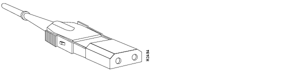
The HP ESCON PA (Figure 1) provides a single channel attachment interface for connecting Cisco 7200 series routers to an ESCON director or to a mainframe channel.
Note
Figure 1 ESCON Channel Port Adapter, Faceplate View
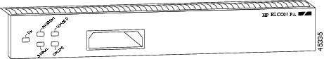
The HP ESCON PA has a single female duplex connector and has 128 MB of DRAM. There are no memory options for the HP ESCON PA.
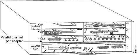
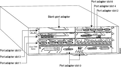
You can install the HP ESCON PA in any of the available port adapter slots in a Cisco 7200 series router. Figure 2 shows an HP ESCON PA installed in port adapter slot 1 of a Cisco 7206.
Figure 2 Cisco 7206 with an HP ESCON PA in Port Adapter Slot 1
Note
The entire HP ESCON PA microcode image is delivered on a router Flash memory card or SanDisk memory device, or you can download it from Cisco.com.
•
•
•
We recommend that you use the version of the HP ESCON PA microcode that is virtually bundled with your Cisco IOS software. If you choose not to, you must copy a microcode image onto the router Flash memory card or SanDisk memory device and use the microcode router configuration command to instruct the Cisco IOS software to use the microcode image you copied instead of the microcode image virtually bundled with your version of the Cisco IOS software.
•
•
•
•
ESCON Specifications
Table 1 lists the specifications for the ESCON interfaces.
Table 1 ESCON Specifications
Supported processor I/O architectures
ESA/390
Bit transmission
Serial
Maximum distance (for LED with ESCON)
1.9 miles (3.1 km) point-to-point
5.7 miles (9.2 km) with two ESCON Directors and each hop not exceeding 3 km.Channel data rate
Up to 17 MBps
Signaling rate
200 Mbps
Cable types
Fiber-optic (62.5/125 micron multimode)
Addition of devices to running systems
Dynamic1
Number of addressable devices per channel
256 x 16 x 16 x 2532
Connectable control units per channel
Up to 59 (through a 9032 ESCON Director)
Connectable channels per adapter
Up to 59 (through a 9032 ESCON Director); varies by control unit
1 The HP ESCON PA requires dynamic = NO with HCD.
2 Where 256 represents available unit addresses, 16 represents the number of logical partitions (LPARs), 16 represents the number of control unit images, and 253 represents the number of ESCON director paths. It is unlikely a system would have the resources to support the total number of available addresses.
LEDs
The functions of the HP ESCON PA LEDs are as follows:
•
•
•
•
•
Figure 3 shows the LED indicators.
Figure 3 HP ESCON PA LED Indicators
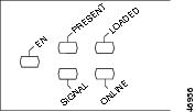
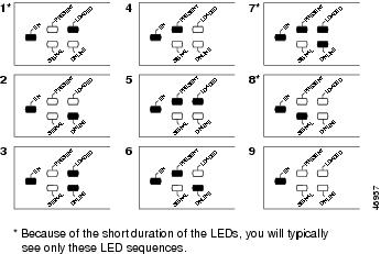
Table 2 shows the HP ESCON PA LED indicator sequences during a cold boot. The ENABLED LED is not part of the following sequences; it remains on during the boot sequence (Figure 4).
Table 2 Cold Boot LED Sequence
1
Off
On
Off
Off
2
Off
Off
Off
On
3
Off
On
Off
On
4
On
Off
Off
Off
5
On
On
Off
Off
6
On
Off
Off
On
7
On
On
Off
On
8
Off
Off
On
Off
91
Off
Off
Off
Off
1 Indicates that the HP ESCON PA is starting to execute the microcode and waiting for commands
Figure 4 LED Boot Sequence
ESCON Cable
The ESCON channel interface uses 62.5/125 micrometer, multimode, fiber-optic cable with male duplex connectors at each end (Figure 5). ESCON cables are not available from Cisco. Refer to the ESCON specifications in and contact your cable supplier or the vendor of your host CPU to order the correct ESCON cable.
Figure 5 ESCON Interface Duplex Connector for the ESCON Channel Port Adapter
Port Adapter Slot Locations on the Supported Platforms
The following sections provide port adapter slot locations and related information:
•
Cisco 7200 Series Routers and Cisco 7200 VXR Routers Slot Numbering
Cisco 7204 routers and Cisco 7204VXR routers have four slots for port adapters, and one slot for an input/output (I/O) controller. The slots are numbered from the lower left to the upper right, beginning with slot 1 and continuing through slot 4. You can place a port adapter in any of the slots (slot 1 through slot 4). Slot 0 is always reserved for the I/O controller. The Cisco 7204 router and Cisco 7204VXR router are not shown.
Cisco 7206 routers and Cisco 7206VXR routers have six slots for port adapters, and one slot for an input/output (I/O) controller. The slots are numbered from the lower left to the upper right, beginning with slot 1 and continuing through slot 6. You can place a port adapter in any of the six slots (slot 1 through slot 6). Slot 0 is always reserved for the I/O controller. Figure 6 shows the slot numbering on a Cisco 7206 router. The Cisco 7206VXR router is not shown.
Note
Figure 6 Port Adapter Slots in the Cisco 7206 Router
Identifying Interface Addresses
This section describes how to identify the interface addresses for the port adapter slots and ESCON channel port numbers. Interface addresses specify the actual physical location of each interface port on the router.
This address is composed of a two-part number in the format port-adapter-slot number/interface-port-number, as follows:
•
•
Note
Interface ports maintain the same address regardless of whether other port adapters are installed or removed from the slot. However, when you move a port adapter to a different slot, the first number in the address changes to reflect the new port adapter slot number.
Note
The following subsections describe the interface address formats for the supported platforms:
•
Table 3 describes the interface addresses for the Cisco 7200 series routers, includingCisco 7200 VXR routers.
Table 3 Identifying Interface Addresses
Cisco 7200 series routers and Cisco 7200 VXR routers (,7204, 7204VXR, 7206, 7206VXR)
Port-adapter-slot-number/interface-port-number
Port adapter slot—11 through 6 (depends on the number of slots in the router)
Interface port—0
1 Port adapter slot 0 is reserved for the Fast Ethernet port on the I/O controller (if present).
Cisco 7200 Series Routers and Cisco 7200 VXR Routers Interface Addresses
In Cisco 7200 series routers, port adapter slot numbers port adapter slots are numbered from the lower left to the upper right, beginning with port adapter slot 1 and continuing through port adapter slot 4 for the Cisco 7204, and slot 6 for the Cisco 7206. Port adapter slot 0 is reserved for the optional Fast Ethernet port on the I/O controller. For ESCON ports, the individual interface port numbers are always 0.
The interface address is composed of a two-part number in the format port-adapter-slot-number/interface-port-number. For example, the ESCON port on an HP ESCON PA in port adapter slot 3 would have the address 3/0. If the HP ESCON PA was in port adapter slot 1, the interface address would be 1/0.
Preparing for Installation
This section describes the general equipment, safety, and site preparation requirements for installing the HP ESCON PA. It also includes microcode overview information.This section contains the following subsections:
•
•
•
Required Tools and Equipment
You need the following parts and tools to install an HP ESCON PA. If you need additional equipment, contact a service representative for ordering information.
•
•
•
HP ESCON PA Microcode Overview
Microcode, also known as firmware, is a set of processor-specific software instructions that enables and manages the features and functions of a specific port adapter type. At system startup or reload, the system loads the microcode for each port adapter type present in the system.
The entire HP ESCON PA microcode image is delivered on a router Flash memory card or SanDisk memory device, or you can download it from Cisco.com.
New microcode is released to enable new features, improve performance, or fix known problems in earlier versions. The Cisco 7200 series routers support downloadable software and microcode images for most upgrades. This support lets you download new or upgraded images remotely, store the images in router memory, and load the new images at system startup without physically accessing the router. You can store multiple versions of an image in Flash or SanDisk memory for a specific processor type, and use configuration commands to specify which version of the image loads at startup. All port adapters of the same type (for example, all HP ESCON PA port adapters) use the same microcode image.
By default, the HP ESCON PA microcode is loaded from the router Flash memory card or SanDisk memory device for the Cisco 7200 series routers. The default HP ESCON PA microcode version is found by entering the show microcode command.
The following example is a partial display of the show microcode command output:
Router# show microcodeMicrocode images for downloadable hardwareHW Type Microcode image names------------------------------------------ecpa default slot0:xcpa28-0configured slot0:xcpa218-2pcpa default slot0:xcpa28-0
Note
Hardware and Software Requirements
The show version command displays the current hardware configuration of the router, including the system software version that is loaded and running. For the HP ESCON PA, the show microcode command lists the recommended and the configured microcode version. The show controller command shows the microcode version running on the HP ESCON PA in the router.
To view the current version of software or microcode stored on the router Flash memory card, use the show flash slot0: or the dir slot0: EXEC commands. Refer to the "Upgrading Your HP ESCON PA Microcode" section for basic configuration information.
If the displays indicate that the required system software and microcode are not available in your system, refer to the "Obtaining Documentation, Obtaining Support, and Security Guidelines" section or contact a service representative for upgrade information.
The following subsections indicate the minimum hardware and software requirements for each supported platform:
•
Cisco 7200 Series Routers and Cisco 7200 VXR Routers Hardware and Software Requirements
The minimum hardware and software requirements for the HP ESCON PA on Cisco 7200 series and Cisco 7200 VXR series routers are:
•
•
Note
•
Table 4 lists the specific Cisco IOS software images that are compatible with the HP ESCON PA.
Table 5 specifies the recommended minimum level of HP ESCON PA microcode for the corresponding Cisco IOS release.
Table 5 Cisco IOS Releases and HP ESCON PA Microcode Image
Release 12.1(5)T
xcpa28-0
For the latest Cisco IOS release that supports the HP ESCON PA on the Cisco 7200 series routers, refer to "Checking Hardware and Software Compatibility" section.
Checking Hardware and Software Compatibility
To check the minimum software requirements of Cisco IOS software with the hardware installed on your router, Cisco maintains the Software Advisor tool on Cisco.com. This tool does not verify whether modules within a system are compatible, but it does provide the minimum IOS requirements for individual hardware modules or components.
Note
To access Software Advisor, click Log In at Cisco.com and go to Support > Tools and Resources. You can also access the tool by pointing your browser directly to http://www.cisco.com/en/US/support/tsd_most_requested_tools.html.
Choose a product family or enter a specific product number to search for the minimum supported software release needed for your hardware.
Safety Guidelines
This section provides safety guidelines that you should follow when working with any equipment that connects to electrical power or telephone wiring.
Safety Warnings
Safety warnings appear throughout this publication in procedures that, if performed incorrectly, might harm you. A warning symbol precedes each warning statement.
Electrical Equipment Guidelines
Follow these basic guidelines when working with any electrical equipment:
•
•
•
•
Preventing Electrostatic Discharge Damage
Electrostatic discharge (ESD) damage, which can occur when electronic cards or components are improperly handled, results in complete or intermittent failures. Port adapters and processor modules comprise printed circuit boards that are fixed in metal carriers. Electromagnetic interference (EMI) shielding and connectors are integral components of the carrier. Although the metal carrier helps to protect the board from ESD, use a preventive antistatic strap during handling.
The following guidelines help prevent ESD damage:
•
•
•
•
•
•
•
•

Caution
Laser LED Safety Information
The HP ESCON PA contains laser LEDs. The expansion module is classified as a Class 1 laser product and is certified to conform to the requirements of EN60825-1:1994 and IEC825-1:1993.
Class 1 laser products are not considered hazardous. The HP ESCON PA has embedded Class 3a laser LED assemblies operating at a nominal wavelength of 850 nanometer and a maximum potential output power of 1.25 milliwatts. The design of the HP ESCON PA incorporates engineering features including current limiting, which ensures that there is no human access to LED radiation greater than Class 1 under any set of operating, maintenance, or service conditions, including a single fault.
There are fewer than 0.442 milliwatts propagating in the link or in any portion of the module. Therefore, according to IEC825-2:1993, Hazard Level 1 prevails in all parts of the system.
The LEDs are located on the front face of the module.
Laser Radiation
Staring into Laser Beam
Removing and Installing Port Adapters
This section describes how to remove port adapters from supported platforms and also how to install new or replacement port adapters.This section contains the following subsections:
•
•
Handling Port Adapters
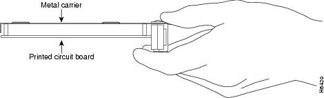
Each port adapter circuit board is mounted to a metal carrier and is sensitive to electrostatic discharge (ESD) damage.
Note
Caution
Figure 7 Handling a Port Adapter
Online Insertion and Removal
The Cisco 7200 series routers, including Cisco 7200 VXR routers, support online insertion and removal (OIR) of all port adapters. You do not need to power down the router when removing and replacing an HP ESCON PA.
Note
OIR allows you to install and replace port adapters while the router is operating; you do not need to notify the software or shut down the system power, although you should not run traffic through the port adapter you are removing while it is being removed. OIR is a method that is seamless to end users on the network, maintains all routing information, and preserves sessions.
It is wise to gracefully shut down the system before removing a port adapter that has active traffic moving through it. Removing a module while traffic is flowing through the ports can cause system disruption. Once the port adapter is inserted, the ports can be brought back up.
The following is a functional description of OIR for background information only; for specific procedures for installing and replacing a port adapter in a supported platform, refer to the "Port Adapter Removal and Installation" section.
Each port adapter has a bus connector that connects it to the router. The connector has a set of tiered pins in three lengths that send specific signals to the system as they make contact with the port adapter. The system assesses the signals it receives and the order in which it receives them to determine if a port adapter is being removed from or introduced to the system. From these signals, the system determines whether to reinitialize a new interface or to shut down a disconnected interface.
Specifically, when you insert a port adapter, the longest pins make contact with the port adapter first, and the shortest pins make contact last. The system recognizes the signals and the sequence in which it receives them.
When you remove or insert a port adapter, the pins send signals to notify the system of changes. The router then performs the following procedure:
1.
2.
3.
Note
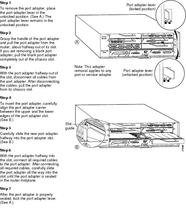
Port Adapter Removal and Installation
In this section, the illustrations that follow give step-by-step instructions on how to remove and install port adapters. Although the procedures may refer to a particular type of port adapter, the steps are the same for installing and removing all types of port adapters. This section contains the following illustrations:
•
Caution

Warning
Caution
Cisco 7200 Series Routers and Cisco 7200 VXR Routers—Removing and Installing a Port Adapter
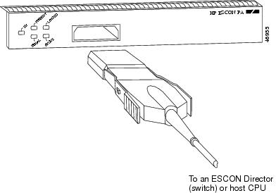
Attaching the HP ESCON PA to the Channel
Caution
To attach the ESCON cable between the HP ESCON PA and the host channel:
Step 1
Note
Step 2
Step 3
Figure 8 Connecting an ESCON Cable to an HP ESCON PA
Step 4
Step 5
Configuring the HP ESCON PA
To continue your port adapter installation, you must configure the HP ESCON PA interface. The instructions that follow apply to all supported platforms. Minor differences among the platforms—with Cisco IOS software commands—are noted.
This section contains the following subsections:
•
•
•
•
Using the EXEC Command Interpreter
You modify the configuration of your router through the software command interpreter called the EXEC (also called enable mode). You must enter the privileged level of the EXEC command interpreter with the enable command before you can use the configure command to configure a new interface or to change the existing configuration of an interface. The system prompts you for a password if one has been set.The system prompt for the privileged level ends with a pound sign (#) instead of an angle bracket (>).
At the console terminal, use the following procedure to enter the privileged level:
Step 1
Router> enablePassword:Step 2
Router#
Configuring the HP ESCON PA Interface
After you verify that the new HP ESCON PA is installed correctly, use the configure command to configure the new interfaces. The enabled LED (EN) goes on when the port adapter is installed correctly (Figure 3). Before you begin to configure the interface, be prepared with the following information:
•
•
•
If you installed a new HP ESCON PA interface or if you want to change the configuration of an existing interface, you must enter configuration mode to configure the new interfaces. If you replaced an HP ESCON PA that was previously configured, the system will recognize the new HP ESCON PA interface and bring it up in its existing configuration. An HP ESCON PA removed from one slot and replaced in another slot must be reconfigured.
Note
The following sections provide specific information about configuring the HP ESCON PA interface:
•
Performing a Basic Interface Configuration
This section describes the procedure for performing a basic configuration of an HP ESCON PA interface.
Press the Return key after each step unless otherwise noted. At any time you can exit the privileged level and return to the user level by entering disable at the prompt as follows:
Router# disableRouter>The following example describes a basic configuration procedure:
Step 1
Router# configure terminalEnter configuration commands, one per line. End with CNTL/Z.Router(config)#Step 2
Router(config)# interface channel 2/0Step 3
Router(config-if)# ip address 1.1.1.10 255.255.255.0Step 4
Step 5
Router(config-if)# no shutdownStep 6
Step 7
Step 8
Router# copy running-config startup-config[OK]Router#
For complete descriptions of interface subcommands and the configuration options available for each platform, refer to the publications listed in the "Related Documentation" section.
To check the interface configuration using show commands, see the "Checking the Configuration" section.
Checking the Configuration
After configuring the new interface, use the show commands to display the status of the new interface or all interfaces and use the ping command to check connectivity. This section includes the following subsections:
•
•
Using show Commands to Verify the New Interface Status
Use show commands to verify that the new interfaces are configured and operating correctly, as follows:
Step 1
Step 2
Step 3
Step 4
Step 5
If the interface is down and you configured it as up, or if the displays indicate that the hardware is not functioning properly, ensure that the network interface is properly connected and terminated. If you still have problems bringing up the interface, contact a service representative for assistance.
This section includes the following subsections:
•
•
•
Using the show version or show hardware Commands
Display the configuration of the router hardware, the software version, the names and sources of configuration files, and the boot images using the show version (or show hardware) command.
Note
Cisco 7200 Series and Cisco 7200 VXR Series Routers—Example Output of the show version Command
Following is an example of the show version command from a Cisco 7200 series router:
Router# show versionCisco Internetwork Operating System SoftwareIOS (tm) 7200 Software (C7200-IS56I-M), Released Version 12.1Copyright (c) 1986-2000 by cisco Systems, Inc.Compiled Thu 27-Jul-00 13:22 by biffImage text-base: 0x60008960, data-base: 0x613C4000ROM: System Bootstrap, Version 12.1 RELEASE SOFTWARE (f)BOOTFLASH: 7200 Software (C7200-BOOT-M), Version 12.1, RELEASE SOFTWARE Rrouter uptime is 5 hours, 6 minutesSystem returned to ROM by reload at 04:35:10 UTC Thu Aug 10 2000System image file is "tftp://181.23.250.2/jdoe/c7200-is56i-mz.121-5.T"cisco 7206VXR (NPE300) processor (revision B) with 122880K/40960K bytes of memo.Processor board ID 15463825R7000 CPU at 262Mhz, Implementation 39, Rev 1.0, 256KB L2, 2048KB L3 Cache6 slot VXR midplane, Version 2.0Last reset from power-onBridging software.X.25 software, Version 3.0.0.4 Ethernet/IEEE 802.3 interface(s)3 FastEthernet/IEEE 802.3 interface(s)2 IBM channel interface(s)125K bytes of non-volatile configuration memory.20480K bytes of Flash PCMCIA card at slot 0 (Sector size 128K).4096K bytes of Flash internal SIMM (Sector size 256K).Configuration register is 0x100Using the show controllers Commands
Display all the current interface processors and their interfaces using the show controllers command.
Note
Cisco 7200 Series and Cisco 7200 VXR Series Routers—Example Output of the show controllers Command
Following is an example of the show controllers command that displays information about a specific HP ESCON PA:
Router# show controllers channel 2/0ECPA 2, hardware version 1.0, microcode version 218.6Mailbox commands:0 forevers, 0 max elapsed usecsMicrocode loaded from flash slot0:xcpa218-6_kernel_ecpa4Loaded:seg_802 Rev. 0 Compiled by jdoe on Thu 07-Sep-2000 12:Loaded:seg_csna Rev. 0 Compiled by jdoe on Thu 07-Sep-2000 12:Loaded:seg_eca Rev. 0 Compiled by jdoe on Thu 07-Sep-2000 12:Loaded:seg_sslc Rev. 0 Compiled by jdoe on Thu 07-Sep-2000 12:Loaded:seg_tcpip Rev. 0 Compiled by jdoe on Thu 07-Sep-2000 12:Loaded:seg_tn3270 Rev. 0 Compiled by jdoe on Thu 07-Sep-2000 12:EPROM version 0.0, VPLD version 0.0ECA0:hw version 02, microcode version C50602D4Load metrics:Memory dram 118412048/128MCPU 1m 1%, 5m 2%, 60m 2%DMA 1m 1%, 5m 0%, 60m 0%ECA0 1m 0%, 5m 0%, 60m 0%Interface Channel2/0Hardware is Escon ChannelHW Registers CPU init=0x021441A0 LED control=0x00045DDF Reset Satus=0x00000002HW Poll Register 4B0D5240:[00000001]Free buffer queuesqueue=0 max_entries=128 size=600 head=71 ring=4B0EB060queue=1 max_entries=32 size=4520 head=23 ring=4B07D380queue=2 max_entries=64 size=4520 head=63 ring=4B07D440Tx Queuesqueue=0 head=0 tail=0 tx_cnt=0 tx_pakcnt=0max_entries=128 type=1 poll_index=0 ring=4B07D580fspak buffers swapped out=0queue=1 head=12 tail=12 tx_cnt=0 tx_pakcnt=0max_entries=32 type=2 poll_index=1 ring=4B0EB2A0fspak buffers swapped out=0Rx Queuesmax_entries=221 poll_index=3 head=96 ring=4B0EB3E0Using the show diag Command
Display the type of port adapter installed in your system using the show diag command.
Note
Cisco 7200 Series and Cisco 7200 VXR Series Routers—Example Output of the show diag Command
Following is an example of the show diag command from a Cisco 7200 series router with an HP ESCON PA installed in port adapter slot 4:
Router# show diag 2Slot 2:Escon Port adapter, 1 portPort adapter is analyzedPort adapter insertion time 00:05:00 agoEEPROM contents at hardware discovery:Hardware Revision :1.0Top Assy. Part Number :800-06347-02Part Number :73-4454-02Board Revision :02PCB Serial Number :18902852000RMA History :00Fab Version :02Fab Part Number :28-3405-02Product Number :PA-4C-EBEEPROM format version 4EEPROM contents (hex):0x00:04 FF 40 02 10 41 01 00 C0 46 03 20 00 18 CB 020x10:82 49 11 66 02 42 30 32 C1 8B 31 38 39 30 32 380x20:35 32 30 30 30 04 00 02 02 85 1C 0D 4D 02 CB 940x30:50 41 2D 34 43 2D 45 42 00 00 00 00 FF FF FF FF0x40:FF FF FF FF FF FF FF FF FF FF FF FF FF FF FF FF0x50:FF FF FF FF FF FF FF FF FF FF FF FF FF FF FF FF0x60:FF FF FF FF FF FF FF FF FF FF FF FF FF FF FF FF0x70:FF FF FF FF FF FF FF FF FF FF FF FF FF FF FF FFUsing the show interfaces Commands
Display information about a specific interface using the show interfaces command.
Note
Cisco 7200 Series and Cisco 7200 VXR Series Routers—Example Output of the show interfaces Command
Following is an example of the show interfaces channel command for an HP ESCON PA in port adapter slot 4:
Router# show interface channel 4/0Channel4/0 is up, line protocol is upHardware is Escon ChannelInternet address is 10.10.99.1/24MTU 4472 bytes, BW 98304 Kbit, DLY 100 usec,reliability 255/255, txload 1/255, rxload 1/255Encapsulation CHANNEL, loopback not setECA adapter cardData transfer rate 12 Mbytes, number of subchannels 0Last input 00:14:09, output 00:00:58, output hang neverLast clearing of "show interface" counters neverQueueing strategy: fifoOutput queue 0/40, 69129 drops; input queue 0/75, 0 drops5 minute input rate 220000 bits/sec, 239 packets/sec5 minute output rate 289000 bits/sec, 252 packets/sec788256 packets input, 84718668 bytes, 0 no bufferReceived 0 broadcasts, 0 runts, 0 giants, 0 throttles0 input errors, 0 CRC, 0 frame, 0 overrun, 0 ignored, 0 abort1378169 packets output, 680323725 bytes, 0 underruns0 output errors, 0 collisions, 7 interface resets0 output buffer failures, 0 output buffers swapped outWith the show interfaces command, use arguments such as the interface type and the port adapter slot and port number to display information about a specific HP ESCON PA.
For complete command descriptions and examples for the Cisco 7200 series routers, refer to the publications listed in the "Related Documentation" section.
Using the Ping Command to Verify Network Connectivity
Use the ping command to verify that an interface port is functioning properly and to check the path between a specific port and connected devices at various locations on the network. This section provides brief descriptions of the ping command. After you verify that the system has booted successfully and is operational, you can use the ping command to verify the status of interface ports.
The ping command sends an echo request out to a remote device at the IP address that you specify. After sending a series of signals, the command waits a specified time for the remote device to echo the signals. Each returned signal is displayed as an exclamation point (!) on the console terminal; each signal that is not returned before the specified time-out is displayed as a period (.). A series of exclamation points (!!!!!) indicates a good connection; a series of periods (.....) or the messages "timed out" or "failed" indicate that the connection failed.
The following example shows a successful ping command to a remote server with the IP address 1.1.1.10:
Router# ping 1.1.1.10Type escape sequence to abort.Sending 5, 100-byte ICMP Echoes to 1.1.1.10, timeout is 2 seconds:!!!!!Success rate is 100 percent (5/5), round-trip min/avg/max = 1/15/64 msRouter#If the connection fails, verify that you have the correct IP address for the server and that the server is active, then repeat the ping command.
For complete descriptions of interface configuration commands and the configuration options available for each platform, refer to the publications listed in the "Related Documentation" section.
Upgrading Your HP ESCON PA Microcode
The following sections discuss HP ESCON PA microcode configuration requirements:
•
•
•
For additional information about specific microcode requirements, refer to the "Hardware and Software Requirements" section.
How Does HP ESCON PA Microcode Ship?
For the Cisco 7200 series routers, when the HP ESCON PA is ordered as part of a new system, the HP ESCON PA microcode is available on a Flash memory card or SanDisk memory device (which also includes the Cisco IOS release compatible with the microcode version) and via Cisco.com. When the HP ESCON PA is ordered as a spare, the HP ESCON PA microcode is available via Cisco.com.
Note
Upgrading the HP ESCON PA Microcode from Cisco.com
To upgrade the HP ESCON PA microcode obtained from Cisco.com, complete the following steps:
Note
Caution
Caution
To upgrade HP ESCON PA microcode images obtained from Cisco.com:
Step 1
Step 2
Step 3
Step 4
Step 5
Step 6
Configuring the HP ESCON PA Microcode
This section describes how to modify the startup configuration to load different microcode images at startup, or to change existing configuration instructions and re-enable the system default.
At system startup or reload, the system loads a microcode image for each processor type. All processors of the same type use the same microcode image; only one image for each type can load at startup. The HP ESCON PA microcode image must be located on a Flash memory card or SanDisk memory device.
When you upgrade software or microcode by downloading new images onto a Flash memory card or SanDisk memory device, you must configure the system to load the new microcode image at startup. Otherwise, the system will continue to load the default image from the system or attempt to load any previous image if it is still specified in the system configuration file.
Note
To instruct the system to load an HP ESCON PA microcode image other than the default at startup, use the microcode ecpa slot:filename and the microcode reload configuration commands to add the instructions to the configuration file.
To load a microcode image from a file stored on a Flash memory card, enter the show flash slot0: EXEC command to display the Flash directory contents and verify the exact name of the file (xcpa28-1 is used in this example):
Router> show flash-#- ED --type-- --crc--- -seek-- nlen -length- -----date/time------ name1 .. unknown CA94D289 20C18 13 2966 Sep 07 2000 09:07:07 ciscocert.pem2 .D unknown 62000000 20C9C 9 1 Sep 18 2000 06:33:57 xcpa218-63 .D unknown 2B04BACB 94134 22 472086 Sep 18 2000 06:33:58 xcpa218-6_kernel_ecpa44 .D unknown 348776FF F9690 21 414940 Sep 18 2000 06:34:21 xcpa218-6_kernel_xcpa5 .D unknown BC7BEC5D 1358B8 17 246184 Sep 18 2000 06:34:42 xcpa218-6_seg_8026 .D unknown C09633A6 1BEFAC 18 562804 Sep 18 2000 06:34:55 xcpa218-6_seg_cmpc7 .D unknown 0B58D705 1D6914 18 96488 Sep 18 2000 06:35:23 xcpa218-6_seg_csna8 .D unknown 29DEAA84 24713C 17 460712 Sep 18 2000 06:35:28 xcpa218-6_seg_eca9 .D unknown 95CADB93 25D904 21 91976 Sep 18 2000 06:35:51 xcpa218-6_seg_offload10 .D unknown 82F8A3D6 26E670 17 68844 Sep 18 2000 06:35:56 xcpa218-6_seg_pca11 .D unknown 7EECB670 272374 18 15492 Sep 18 2000 06:35:59 xcpa218-6_seg_push12 .D unknown B4A58886 33C564 18 827760 Sep 18 2000 06:36:00 xcpa218-6_seg_sslc13 .D unknown 73CB2859 363B90 19 161196 Sep 18 2000 06:36:41 xcpa218-6_seg_tcpip14 .D unknown 0989F473 409EF0 20 680672 Sep 18 2000 06:36:49 xcpa218-6_seg_tn327015 .. unknown 62000000 409F74 9 1 Sep 18 2000 06:46:12 xcpa218-616 .. unknown 2B04BACB 47D40C 22 472086 Sep 18 2000 06:46:12 xcpa218-6_kernel_ecpa417 .. unknown 348776FF 4E2968 21 414940 Sep 18 2000 06:46:35 xcpa218-6_kernel_xcpa18 .. unknown BC7BEC5D 51EB90 17 246184 Sep 18 2000 06:46:56 xcpa218-6_seg_80219 .. unknown C09633A6 5A8284 18 562804 Sep 18 2000 06:47:09 xcpa218-6_seg_cmpc20 .. unknown 0B58D705 5BFBEC 18 96488 Sep 18 2000 06:47:37 xcpa218-6_seg_csna21 .. unknown 29DEAA84 630414 17 460712 Sep 18 2000 06:47:42 xcpa218-6_seg_eca22 .. unknown 95CADB93 646BDC 21 91976 Sep 18 2000 06:48:05 xcpa218-6_seg_offload23 .. unknown 82F8A3D6 657948 17 68844 Sep 18 2000 06:48:10 xcpa218-6_seg_pca24 .. unknown 7EECB670 65B64C 18 15492 Sep 18 2000 06:48:13 xcpa218-6_seg_push25 .. unknown B4A58886 72583C 18 827760 Sep 18 2000 06:48:14 xcpa218-6_seg_sslc26 .. unknown 73CB2859 74CE68 19 161196 Sep 18 2000 06:48:56 xcpa218-6_seg_tcpip27 .. unknown 0989F473 7F31C8 20 680672 Sep 18 2000 06:49:04 xcpa218-6_seg_tn327012373560 bytes available (8204744 bytes used)To configure the microcode for an HP ESCON PA on a router configured with Cisco IOS Release 12.1(5)T or later:
Step 1
Router> enablePassword:Router#
Note
Step 2
Step 3
Router# configure terminalTo load the microcode from an individual microcode image that is stored as a file on a Flash memory card, enter the microcode command, the processor type, the specific memory location of the HP ESCON PA microcode image, and the exact argument for filename (xcpa28-1 is used in this example):
Router(config)# microcode ecpa slot0:xcpa28-1Router(config)# microcode reload
Note
The no microcode command cancels any existing instructions to load an image from a Flash memory card and restores the default configuration:
Router(config)# no microcode ecpa slot0:xcpa28-1Step 4
Router# copy running-config startup-configStep 5
Step 6
Using Flash Memory
The following provides information on the different functions of Flash memory that you might need when configuring microcode:
•
•
•
Copying a New Image to the Flash Memory Card on a Cisco 7200 Series Router
Copying a new image to a Flash memory card might be required when a new microcode image becomes available. Use the command copy tftp:filename [ bootflash | slot0 | slot1 ]:filename for the copy procedure, where tftp:filename is the source of the file and [ bootflash | slot0 | slot1 ]:filename is the destination in onboard Flash memory or on either of the Flash memory cards.
The following example shows the output from the copy tftp:filename command for Cisco IOS Release 12.0:
Router# copy tftp:xcpa28-6 slot0:xcpa28-6Address or name of remote host [181.23.250.2]?Accessing tftp://181.23.250.2/jdoe/xcpa218-6...Loading jdoe/xcpa218-6 from 181.23.250.2(via Ethernet3/0):!Expanding slot0:/xcpa218-6_kernel_ecpa4 (472086 bytes):!!!!!!!!!!!!!!!!!!!!!!!!!!!!!!!!!!!!!!!!!!!!!!!!!!!!!!!!!!!!!!!!!!!!!!!!!!!!!!!!!!!!!!!!!!!!Expanding slot0:/xcpa218-6_kernel_xcpa (414940 bytes):!!!!!!!!!!!!!!!!!!!!!!!!!!!!!!!!!!!!!!!!!!!!!!!!!!!!!!!!!!!!!!!!!!!!!!!!!!!!!!!!!!!Expanding slot0:/xcpa218-6_seg_802 (246184 bytes):!!!!!!!!!!!!!!!!!!!!!!!!!!!!!!!!!!!!!!!!!!!!!!!!!!Expanding slot0:/xcpa218-6_seg_cmpc (562804 bytes):!!!!!!!!!!!!!!!!!!!!!!!!!!!!!!!!!!!!!!!!!!!!!!!!!!!!!!!!!!!!!!!!!!!!!!!!!!!!!!!!!!!!!!!!!!!!!!!!!!!!!!!!!!!!!!Expanding slot0:/xcpa218-6_seg_csna (96488 bytes):!!!!!!!!!!!!!!!!!!!!Expanding slot0:/xcpa218-6_seg_eca (460712 bytes):!!!!!!!!!!!!!!!!!!!!!!!!!!!!!!!!!!!!!!!!!!!!!!!!!!!!!!!!!!!!!!!!!!!!!!!!!!!!!!!!!!!!!!!!!!!Expanding slot0:/xcpa218-6_seg_offload (91976 bytes):!!!!!!!!!!!!!!!!!!Expanding slot0:/xcpa218-6_seg_pca (68844 bytes):!!!!!!!!!!!!!Expanding slot0:/xcpa218-6_seg_push (15492 bytes):!!!Expanding slot0:/xcpa218-6_seg_sslc (827760 bytes):!!!!!!!!!!!!!!!!!!!!!!!!!!!!!!!!!!!!!!!!!!!!!!!!!!!!!!!!!!!!!!!!!!!!!!!!!!!!!!!!!!!!!!!!!!!!!!!!!!!!!!!!!!!!!!!!!!!!!!!!!!! !!!!!!!!!!!!!!!!!!!!!!!!!!!!!!!!!!!!!!!!Expanding slot0:/xcpa218-6_seg_tcpip (161196 bytes):!!!!!!!!!!!!!!!!!!!!!!!!!!!!!!!Expanding slot0:/xcpa218-6_seg_tn3270 (680672 bytes):!!!!!!!!!!!!!!!!!!!!!!!!!!!!!!!!!!!!!!!!!!!!!!!!!!!!!!!!!!!!!!!!!!!!!!!!!!!!!!!!!!!!!!!!!!!!!!!!!!!!!!!!!!!!!!!!!!!!! !!!!!!!!!!!!!!!![OK - 4109312/8218624 bytes]4109312 bytes copied in 206.344 secs (19948 bytes/sec)
Note
Using Additional Flash Memory Commands
There are additional commands related to the bootflash Flash memory in the Cisco 7200 series router (called bootflash) and in PCMCIA Flash memory cards. The following example assumes you are currently accessing the Flash memory card in PCMCIA slot 0. You can determine which PCMCIA slot you are accessing using the pwd command as follows:
Router# pwdslot0You can move between Flash memory media using the cd [bootflash: | slot0: | slot1:] command:
Router# cd slot0:slot0Router# cd slot1:Router# pwdslot1You can list the directory of any Flash memory media using the dir [ bootflash: | slot0: | slot1: ] command:
Router# dir-#- -length- -----date/time------ name1 4601977 May 19 2000 09:42:19 myfile16 679 May 19 2000 05:43:56 todays-config7 1 May 19 2000 09:54:53 fun1You can delete a file from any Flash memory media using the delete command:
Router# delete slot0:fun1Router# dir-#- -length- -----date/time------ name1 4601977 May 19 2000 09:42:19 myfile16 679 May 19 2000 05:43:56 todays-configTo verify that the delete command was successful, use the dir /deleted command to view the deleted files.
Note
You can permanently removes files, which are marked as deleted, and push together all other undeleted files to eliminate spaces between them using the squeeze command:
Router# squeeze slot0:All deleted files will be removed, proceed? [confirm]Squeeze operation may take a while, proceed? [confirm]ebESZTo prevent loss of data because of sudden power loss, the "squeezed" data is temporarily saved to a special location of Flash memory.
In the squeeze command display output, the displayed characters have the following meaning:
•
•
•
•
•
The squeeze command automatically tracks which of these functions has been performed so upon sudden power failure, it can safely continue with the process.
Recovering from Locked Blocks
A locked block of Flash memory occurs when power is lost or a Flash memory card is unplugged during a write or erase operation. When a block of Flash memory is locked, it cannot be written to or erased, and the operation will consistently fail at a particular block location. The only way to recover from locked blocks is by reformatting the Flash memory card with the format command.
Caution
Using SanDisk Devices
PCMCIA Flash memory cards use a slot0/slot1 convention to specify memory locations; slot0 is the default directory for IOS searches. However, SanDisk memory devices use a disk0/disk1 convention. Therefore, when you use a SanDisk device on a Cisco 7200 series router, you need to specify disk0 or disk1 explicitly in IOS search arguments.
For example, to copy a new microcode image to a Sandisk device, use the following command:
copy tftp:source_filename {disk0 | disk1}:sandisk_filename
where:
•
•
The following example shows sample output for the copy tftp:filename command:
Router# copy tftp:xcpa27-1 disk0:xcpa27-12283972 bytes available on device flash, proceed? [confirm]Address or name of remote host [biff.cisco.com]? [confirm]Source filename [xcpa27-1]? [confirm]Destination filename [xcpa27-1]? [confirm]Accessing file "xcpa27-1" on biff.cisco.com ...Loading xcpa26-1 from 1.1.1.22 (via FastEthernet0/0):!Expanding disk0:xcpa27-1_kernel_xcpa (406910 bytes):!!!!!!!!!!!Expanding disk0:xcpa27-1_seg_802 (245522 bytes):!!!!!!!!!!!Expanding disk0:xcpa27-1_seg_cmpc (564632 bytes):!!!!!!!!!!!Expanding disk0:xcpa27-1_seg_csna (96024 bytes):!!!!!!!!!!!Expanding disk0:xcpa27-1_seg_eca (460704 bytes):!!!!!!!!!!!Expanding disk0:xcpa27-1_seg_offload (91420 bytes):!!!!!!!!!!!Expanding disk0:xcpa27-1_seg_pca (68840 bytes):!!!!!!!!!!!Expanding disk0:xcpa27-1_seg_push (15488 bytes):!!!!!!!!!!!Expanding disk0:xcpa27-1_seg_tcpip (161140 bytes):!!!!!!!!!!!Expanding disk0:xcpa27-1_seg_tn3270 (620400 bytes):!!!!!!!!!!![OK - 2739200/5478400 bytes]2739200 bytes copied in 68.500 secs (40282 bytes/sec)To update your running configuration:
Step 1
Router# configuration termRouter(config)# microcode ecpa diskX:xcpaXX-YYRouter(config)# microcode reloadRouter(config)# endwhere:
–
–
Step 2
Running HP ESCON PA Diagnostic Tests
The HP ESCON PA diagnostic test routines are as follows:
•
•
•
•
•
•
Note
This document is to be used in conjunction with the documents listed in the Preparing for Installation section.

Copyright © 2003-2007 Cisco Systems, Inc. All rights reserved.


 Feedback
Contact Cisco
- Open a Support Case

- (Requires a Cisco Service Contract)