PA-1C-E ESCON Channel Port Adapter Installation and Configuration
Available Languages
Table Of Contents
PA-1C-E ESCON Channel Port Adapter
Installation and ConfigurationObtaining Technical Assistance
Port Adapter Installation Prerequisites
Software and Hardware Requirements
Checking Hardware and Software Compatibility
ESCON Channel Port Adapter Microcode Overview
Electrical Equipment Guidelines
What is the ESCON Channel Port Adapter
ESCON Channel Port Adapter Overview
ESCON Channel Port Adapter Description
ESCON Channel Port Adapter DRAM Configurations
Port Adapter Locations in Cisco 7200-Series Routers
ESCON Channel Port Adapter LED Indicators and Sequences
Using the ESCON Channel Port Adapter in Cisco 7200-Series Routers
Installing or Replacing a Port Adapter in Cisco 7200-Series Routers
Attaching the ESCON Channel Port Adapter to the Channel
Using the EXEC Command Interpreter
Configuring ESCON Channel Port Adapter Interface
Selecting Port Adapter Slots and ESCON Channel Port Numbers
ESCON Channel Port Adapter Microcode Guidelines
How Does ESCON Channel Port Adapter Microcode Ship?
ESCON Channel Port Adapter Microcode Upgrade Overview
Copying to the Flash Memory Card on a Cisco 7200-Series Router
Additional Flash Memory Commands
Running ESCON Channel Port Adapter Diagnostic Tests
PA-1C-E ESCON Channel Port Adapter
Installation and Configuration
Product Number: PA-1C-E(=)
This document contains instructions for installing and configuring the Enterprise Systems Connection (ESCON) IBM Channel Port Adapter (PA-1C-E), which is used in the Cisco 7200-series routers.
For complete descriptions of interface configuration commands and the configuration options available for Cisco 7200-series interfaces that support the ESCON Channel Port Adapter functionality, refer to the appropriate software configuration publication listed in the "Obtaining Documentation" section.

Note
Cisco IOS Release 11.3(3)T and later supports the ESCON Channel Port Adapter. When ordered as a spare, the ESCON Channel Port Adapter microcode is available via Cisco.com. When ordered as part of a new system, the ESCON Channel Port Adapter microcode is available on Flash memory cards and SanDisk memory devices (which also include the Cisco IOS release compatible with the microcode version) and via Cisco.com. When the ESCON Channel Port Adapter is shipped with a new system, there is a default setting in Cisco IOS that points to the ESCON Channel Port Adapter microcode with which it has been virtually bundled (separately bundled and preloaded onto the Flash memory card or SanDisk memory device along with the compatible Cisco IOS software). The Cisco IOS software loads the ESCON Channel Port Adapter microcode image onto the port adapter when the router boots and when an ESCON Channel Port Adapter is inserted into a router that has already been booted.
We recommend that you use the version of the ESCON Channel Port Adapter microcode that is virtually bundled with your Cisco IOS software. If you choose not to, you must then copy a microcode image onto the router Flash memory card or SanDisk memory device and use the microcode router configuration command to instruct the Cisco IOS software to use this microcode image instead of the microcode image virtually bundled with your version of the Cisco IOS software.
For instructions on placing ESCON Channel Port Adapter microcode on the router Flash memory card, see the "Copying to the Flash Memory Card on a Cisco 7200-Series Router" section.
For instructions on placing ESCON Channel Port Adapter microcode on the SanDisk memory device, see the "Using SanDisk Devices" section.
For instructions on configuring Cisco IOS to use an ESCON Channel Port Adapter image from the router Flash memory card or SanDisk memory device, refer to the "Configuring Microcode" section.
For general information on ESCON Channel Port Adapter microcode, refer to the "ESCON Channel Port Adapter Microcode Overview" section. For specific instructions to configure the Cisco IOS software to download microcode from the router Flash memory card or SanDisk memory device, refer to the "ESCON Channel Port Adapter Microcode Upgrade Overview" section.
Document Contents
This configuration note is organized into the following sections:
•
•
•
•
•
•
Related Documentation
The documentation listed below is available online, on the Documentation CD-ROM, or as printed documents.
Your router, switch, or gateway and the Cisco IOS software running on it contain extensive features and functionality, which are documented in the following resources:
•
–
–
Note
•
–
–
–
–
•
For hardware installation and maintenance information, refer to the Cisco 7200 VXR Installation and Configuration Guide or the Cisco 7200 VXR Quick Start Guide.
•
–
–
–
•
–
–
Obtaining Documentation
The following sections explain how to obtain documentation from Cisco Systems.
World Wide Web
You can access the most current Cisco documentation on the World Wide Web at the following URL:
Translated documentation is available at the following URL:
http://www.cisco.com/public/countries_languages.shtml
Documentation CD-ROM
Cisco documentation and additional literature are available in a Cisco Documentation CD-ROM package, which is shipped with your product. The Documentation CD-ROM is updated monthly and may be more current than printed documentation. The CD-ROM package is available as a single unit or through an annual subscription.
Ordering Documentation
Cisco documentation is available in the following ways:
•
http://www.cisco.com/cgi-bin/order/order_root.pl
•
http://www.cisco.com/go/subscription
•
Documentation Feedback
If you are reading Cisco product documentation on Cisco.com, you can submit technical comments electronically. Click Leave Feedback at the bottom of the Cisco Documentation home page. After you complete the form, print it out and fax it to Cisco at 408 527-0730.
You can e-mail your comments to bug-doc@cisco.com.
To submit your comments by mail, use the response card behind the front cover of your document, or write to the following address:
Cisco Systems
Attn: Document Resource Connection
170 West Tasman Drive
San Jose, CA 95134-9883We appreciate your comments.
Obtaining Technical Assistance
Cisco provides Cisco.com as a starting point for all technical assistance. Customers and partners can obtain documentation, troubleshooting tips, and sample configurations from online tools by using the Cisco Technical Assistance Center (TAC) Web Site. Cisco.com registered users have complete access to the technical support resources on the Cisco TAC Web Site.
Cisco.com
Cisco.com is the foundation of a suite of interactive, networked services that provides immediate, open access to Cisco information, networking solutions, services, programs, and resources at any time, from anywhere in the world.
Cisco.com is a highly integrated Internet application and a powerful, easy-to-use tool that provides a broad range of features and services to help you to
•
•
•
•
•
You can self-register on Cisco.com to obtain customized information and service. To access Cisco.com, go to the following URL:
Technical Assistance Center
The Cisco TAC is available to all customers who need technical assistance with a Cisco product, technology, or solution. Two types of support are available through the Cisco TAC: the Cisco TAC Web Site and the Cisco TAC Escalation Center.
Inquiries to Cisco TAC are categorized according to the urgency of the issue:
•
•
•
•
Which Cisco TAC resource you choose is based on the priority of the problem and the conditions of service contracts, when applicable.
Cisco TAC Web Site
The Cisco TAC Web Site allows you to resolve P3 and P4 issues yourself, saving both cost and time. The site provides around-the-clock access to online tools, knowledge bases, and software. To access the Cisco TAC Web Site, go to the following URL:
All customers, partners, and resellers who have a valid Cisco services contract have complete access to the technical support resources on the Cisco TAC Web Site. The Cisco TAC Web Site requires a Cisco.com login ID and password. If you have a valid service contract but do not have a login ID or password, go to the following URL to register:
http://www.cisco.com/register/
If you cannot resolve your technical issues by using the Cisco TAC Web Site, and you are a Cisco.com registered user, you can open a case online by using the TAC Case Open tool at the following URL:
http://www.cisco.com/tac/caseopen
If you have Internet access, it is recommended that you open P3 and P4 cases through the Cisco TAC Web Site.
Cisco TAC Escalation Center
The Cisco TAC Escalation Center addresses issues that are classified as priority level 1 or priority level 2; these classifications are assigned when severe network degradation significantly impacts business operations. When you contact the TAC Escalation Center with a P1 or P2 problem, a Cisco TAC engineer will automatically open a case.
To obtain a directory of toll-free Cisco TAC telephone numbers for your country, go to the following URL:
http://www.cisco.com/warp/public/687/Directory/DirTAC.shtml
Before calling, please check with your network operations center to determine the level of Cisco support services to which your company is entitled; for example, SMARTnet, SMARTnet Onsite, or Network Supported Accounts (NSA). In addition, please have available your service agreement number and your product serial number.
Port Adapter Installation Prerequisites
This section provides software and hardware requirements, a list of parts and tools you will need to install the port adapter, and safety and electrostatic discharge (ESD)-prevention guidelines to help you avoid injury and damage to the equipment during installation. Also included is information on the systems in which you can install the port adapters overview information on interface specifications.
The following sections discuss general information about port adapter installation requirements:
•
•
•
Software and Hardware Requirements
The following hardware and software prerequisites ensure proper operation of the ESCON Channel Port Adapter:
•
•
Note
•
Table 1 lists the specific Cisco IOS software images that are compatible with the ESCON Channel Port Adapter.
Table 1 Cisco IOS Release Image Names
Table 2 specifies the recommended minimum level of ESCON Channel Port Adapter microcode for a corresponding Cisco IOS release.
Table 2 Cisco IOS Releases and ESCON Channel Port Adapter Microcode Image
The show version command displays the current hardware configuration of the router, including the system software version that is loaded and running. For the ESCON Channel Port Adapter, the show microcode command lists the recommended and the configured microcode version. The show controller command shows the microcode version running on the ESCON Channel Port Adapter in the router. For additional descriptions of configuration commands, refer to the publications listed in the "Related Documentation" section.
You can view the current version of software or microcode stored on the router Flash memory card by using the show flash slot0: or the dir slot0: EXEC commands. Refer to the "ESCON Channel Port Adapter Microcode Guidelines" section for basic configuration information and refer to the appropriate software documentation for complete configuration instructions and examples, which are listed in the "Related Documentation" section.
If the displays indicate that the required system software and microcode are not available in your system, refer to the "Obtaining Documentation" section or contact a service representative for upgrade information.
Checking Hardware and Software Compatibility
To check the minimum software requirements of Cisco IOS software with the hardware installed on your router, Cisco maintains the Software Advisor tool on Cisco.com. This tool does not verify whether modules within a system are compatible, but it does provide the minimum IOS requirements for individual hardware modules or components.
Note
To access Software Advisor, click Login at Cisco.com and go to Technical Support Help—Cisco TAC: Tool Index: Software Advisor. You can also access the tool by pointing your browser directly to http://www.cisco.com/cgi-bin/support/CompNav/Index.pl.
Choose a product family or enter a specific product number to search for the minimum supported software release needed for your hardware.
ESCON Channel Port Adapter Microcode Overview
Microcode, also known as firmware, is a set of processor-specific software instructions that enables and manages the features and functions of a specific port adaptor type. At system startup or reload, the system loads the microcode for each port adaptor type present in the system.
The entire ESCON Channel Port Adapter microcode image is delivered on a router Flash memory card or SanDisk memory device, or you can download it from Cisco.com.
New microcode is released to enable new features, improve performance, or fix known problems in earlier versions. The Cisco 7200-series routers support downloadable software and microcode images for most upgrades. This support lets you download new or upgraded images remotely, store the images in router memory, and load the new images at system startup without physically accessing the router. You can store multiple versions of an image in Flash or SanDisk memory for a specific processor type, and use configuration commands to specify which version of the image loads at startup. All port adapters of the same type (for example, all ESCON Channel Port Adapters) use the same microcode image.

Caution
By default, the ESCON Channel Port Adapter microcode is loaded from the router Flash memory card or SanDisk memory device for the Cisco 7200-series routers. The default ESCON Channel Port Adapter microcode version is found by entering the show microcode command.
The following example is a partial display of the show microcode command output:
Router# show microcodeMicrocode images for downloadable hardwareHW Type Microcode image names------------------------------------------ecpa default slot0:xcpa26-1configured slot0:xcpa214-10pcpa default slot0:xcpa26-1(additional display text omitted from this example)
Note
List of Parts and Tools
You need the following parts and tools to install a port adapter. If you need additional equipment, contact a service representative for ordering information.
•
•
•
Safety Guidelines
This section provides safety guidelines that you should follow when working with any equipment that connects to electrical power or telephone wiring.
Safety Warnings
Safety warnings appear throughout this publication in procedures that, if performed incorrectly, might harm you. A warning symbol precedes each warning statement.
Electrical Equipment Guidelines
Follow these basic guidelines when working with any electrical equipment:
•
•
•
•
Preventing ESD Damage
ESD damage, which can occur when electronic cards or components are improperly handled, results in complete or intermittent failures. Port adapters and processor modules comprise printed circuit boards that are fixed in metal carriers. Electromagnetic interference (EMI) shielding and connectors are integral components of the carrier. Although the metal carrier helps to protect the board from ESD, use a preventive antistatic strap during handling.
The following guidelines help prevent ESD damage:
•
•
•
•
•
•
•
•
Caution
Laser LED Safety Information
The ESCON Channel Port Adapter contains laser LEDs. The expansion module is classified as a Class 1 laser product and is certified to conform to the requirements of EN60825-1:1994 and IEC825-1:1993.
Class 1 laser products are not considered hazardous. The ESCON Channel Port Adapter has embedded Class 3a laser LED assemblies operating at a nominal wavelength of 850 nanometer and a maximum potential output power of 1.25 milliwatts. The design of the ESCON Channel Port Adapter incorporates engineering features including current limiting, which ensures that there is no human access to LED radiation greater than Class 1 under any set of operating, maintenance, or service conditions, including a single fault.
There are fewer than 0.442 milliwatts propagating in the link or in any portion of the module. Therefore, according to IEC825-2:1993, Hazard Level 1 prevails in all parts of the system.
The LEDs are located on the front face of the module.
Laser Radiation Warning

Warning
Waarschuwing Laserstraling wanneer geopend.
Varoitus Lasersäteitä aukkojen ollessa avoinna.
Attention Production d'un rayonnement laser en position ouverte.
Warnung Laserstrahlung in geöffnetem Zustand
Avvertenza Emette radiazioni laser quando è aperto.
Advarsel Laserstråling er til stede når enheten er åpen.
Aviso Radiação laser presente quando aberto.
¡Advertencia! Radiación láser cuando está abierto.
Varning! Rikta inte blicken in mot strålen.
Laser Beam Exposure Warning
Warning
Waarschuwing Niet in de straal staren.
Varoitus Älä katso säteeseen.
Attention Ne pas fixer le faisceau des yeux.
Warnung Nicht direkt in den Strahl blicken.
Avvertenza Non fissare il raggio con gli occhi.
Advarsel Stirr ikke på strålen.
Aviso Não olhe fixamente para o raio.
¡Advertencia! No mirar fijamente el haz.
Varning! Laserstrålning när enheten är öppen.
What is the ESCON Channel Port Adapter
This section discusses channel attachment and the ESCON Channel Port Adapter, its LED functions, and its memory and cable requirements.
The following information is included in this section:
•
•
Channel Attachment Overview
A mainframe channel (referred to as a channel) is an intelligent processor that manages the protocol on the communications media and controls the data transfer to and from the main central processing unit (CPU) storage. Devices called input/output processors (IOPs) communicate between the host CPU and the channel. One IOP controls multiple channels. There is no relationship between the number of CPUs and the number of IOPs.
The channel relieves the mainframe CPU of direct communication with input/output (I/O) devices, which saves processing cycles and allows data processing and communications tasks to run concurrently. Channels use one or more channel paths as the links between mainframes and I/O devices. I/O devices are connected directly to control units, which provide the logical capabilities required to operate and control the I/O devices.
ESCON Channel Port Adapter Overview
An ESCON Channel Port Adapter provides a single channel interface for Cisco 7200-series routers. In some situations, this interface can eliminate the need for a separate front-end processor (FEP). The ESCON Channel Port Adapter contains an ESCON I/O connector.
The ESCON Channel Port Adapter is a high-bandwidth port adapter. A Fast Ethernet port adapter is an example of another type of high-speed port adapter. A single Cisco 7200-series router can support up to three high-speed port adapters.
Note
ESCON Channel Port Adapter Description
The following information is included in this section:
•
•
•
ESCON General Layout
The ESCON Channel Port Adapter (Figure 1) provides a single channel attachment interface for connecting Cisco 7200-series routers to an ESCON director or to a mainframe channel.
Note
Figure 1 ESCON Channel Port Adapter, Faceplate View
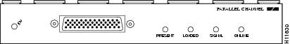
The ESCON Channel Port Adapter has a single female duplex connector.
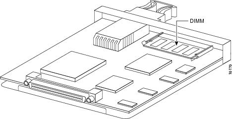
The ESCON Channel Port Adapter has a single DRAM dual in-line memory module (DIMM) and comes configured with 16 MB of DRAM as the minimum standard, and default, memory configuration (Figure 2).
Figure 2 ESCON Channel Port Adapter DRAM DIMM Location
ESCON Channel Port Adapter DRAM Configurations
Each ESCON Channel Port Adapter model is available in the following configurations of DRAM DIMM:
•
•
•
Note
ESCON Channel Port Adapter DRAM can be upgraded in the field by Cisco-certified service personnel only.
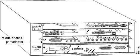
Port Adapter Locations in Cisco 7200-Series Routers
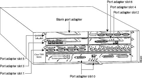
In Cisco 7200-series routers, which consist of the Cisco 7204 and the Cisco 7206, port adapter slots are numbered from the lower left to the upper right, beginning with port adapter slot 1 and continuing through port adapter slot 4 for the Cisco 7204, and slot 6 for the Cisco 7206. Port adapter slot 0 is reserved for the optional Fast Ethernet port on the I/O controller. Figure 3 shows a Cisco 7206 with port adapters installed.
Note
Figure 3 Cisco 7200-Series Port Adapters (Cisco 7206)
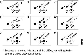
ESCON Channel Port Adapter LED Indicators and Sequences
The functions of the ESCON Channel Port Adapter LEDs are as follows:
•
•
•
•
•
Figure 4 shows the LED indicators.
Figure 4 ESCON Channel Port Adapter LED Indicators
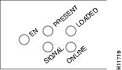
Table 3 shows the ESCON Channel Port Adapter LED indicator sequences during a cold boot. The enabled LED is not part of the following sequences; it remains on during the boot sequence (Figure 5).
Table 3 Cold Boot LED Sequence
1
Off
On
Off
Off
2
Off
Off
Off
On
3
Off
On
Off
On
4
On
Off
Off
Off
5
On
On
Off
Off
6
On
Off
Off
On
7
On
On
Off
On
8
Off
Off
On
Off
91
Off
Off
Off
Off
1 Indicates that the ESCON Channel Port Adapter is starting to execute the microcode and waiting for commands
Figure 5 LED Boot Sequence
ESCON Specifications
Table 4 lists the specifications for the ESCON interfaces.
Table 4 ESCON Specifications
Supported processor I/O architectures
ESA/390
Bit transmission
Serial
Maximum distance (for LED with ESCON)
1.9 miles (3.1 km) point-to-point
5.7 miles (9.2 km) with two ESCON Directors and each hop not exceeding 3 km.Channel data rate
Up to 17 MBps
Signaling rate
200 Mbps
Cable types
Fiber-optic (62.5/125 micron multimode)
Addition of devices to running systems
Dynamic1
Number of addressable devices per channel
256 x 16 x 16 x 2532
Connectable control units per channel
Up to 59 (through a 9032 ESCON Director)
Connectable channels per adapter
Up to 59 (through a 9032 ESCON Director); varies by control unit
1 The ESCON Channel Port Adapter requires dynamic = NO with HCD.
2 Where 256 represents available unit addresses, 16 represents the number of logical partitions (LPARs), 16 represents the number of control unit images, and 253 represents the number of ESCON director paths. It is unlikely a system would have the resources to support the total number of available addresses.
ESCON Cable
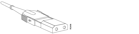
The ESCON channel interface uses 62.5/125 micrometer, multimode, fiber-optic cable with male duplex connectors at each end (Figure 6). ESCON cables are not available from Cisco. Refer to the ESCON specifications in Table 4 and contact your cable supplier or the vendor of your host CPU to order the correct ESCON cable.
Figure 6 ESCON Interface Duplex Connector for the ESCON Channel Port Adapter
Using the ESCON Channel Port Adapter in Cisco 7200-Series Routers
The following sections include information about using the ESCON Channel Port Adapter in the Cisco 7200-series routers:
•
•
•
•
You can install the ESCON Channel Port Adapter in any of the available port adapter slots in a Cisco 7200-series router. Figure 7 shows an ESCON Channel Port Adapter installed in port adapter slot 1 of a Cisco 7206.
Figure 7 Cisco 7206 with an ESCON Channel Port Adapter in Port Adapter Slot 1
Caution
Installing or Replacing a Port Adapter in Cisco 7200-Series Routers
Note
When a port adapter slot is not in use, a blank port adapter must fill the empty slot to allow the router to conform to EMI emissions requirements and to allow proper air flow across the port adapters. If you plan to install a new port adapter in a slot that is not in use, you must first remove the blank port adapter.
The following sections describe how to remove and replace a port adapter:
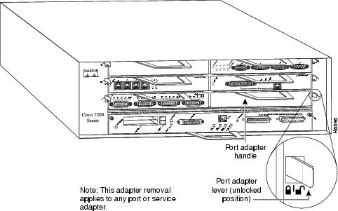
Removing a Port Adapter
You do not need to power down the Cisco 7200-series routers when removing and replacing ESCON Channel Port Adapters; however, to prevent a possible interface control check on the mainframe, consult with your system administrator to take appropriate precautions.
The following procedure describes how to remove a port adapter from a Cisco 7200-series router:
Step 1
Step 2
Figure 8 Placing the Port Adapter Lever in the Unlocked Position (Cisco 7206)
Step 3
Note
Step 4
Step 5
Caution
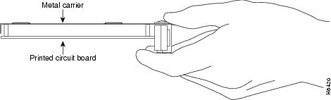
Figure 9 Handling a Port Adapter
Step 6
Replacing a Port Adapter
The following procedure describes how to replace a port adapter in a Cisco 7200-series router:
Step 1
Step 2
Step 3
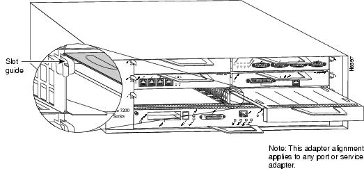
Figure 10 Align the Port Adapter Metal Carrier Between the Slot Guides (Cisco 7206)
Step 4
Caution
Step 5
Step 6
Step 7
Note
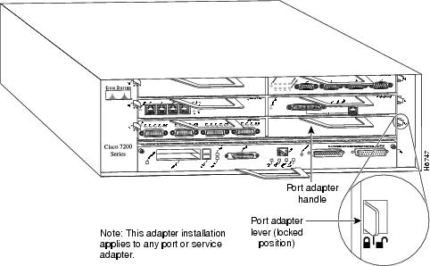
Figure 11 Port Adapter Lever in the Locked Position (Cisco 7206)
Attaching the ESCON Channel Port Adapter to the Channel
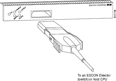
The following procedure describes how to attach the ESCON cable between the ESCON Channel Port Adapter and the host channel.
Caution
Step 1
Step 2
Figure 12 Connecting an ESCON Cable to the ESCON Channel Port Adapter
Step 3
Step 4
Using the EXEC Command Interpreter
You modify the configuration of your router through the software command interpreter called the EXEC. You must enter the privileged level of the EXEC command interpreter with the enable command before you can use the configure command to configure a new interface or to change the existing configuration of an interface. The EXEC command interpreter prompts you for a password if one has been set.
The system prompt for the privileged level ends with a pound sign (#) instead of an angle bracket (>). At the console terminal, use the following procedure to enter the privileged EXEC level:
Step 1
Router> enablePassword:Step 2
Step 3
Router#
Proceed to the following section to configure the new interfaces.
Configuring ESCON Channel Port Adapter Interface
If you installed a new ESCON Channel Port Adapter or if you want to change the configuration of an existing interface, you must use the privileged EXEC configure command. If you remove and replace an ESCON Channel Port Adapter in the same slot that was previously configured, the system will recognize the new ESCON Channel Port Adapter interface and bring it up in its existing configuration. An ESCON Channel Port Adapter removed from one slot and replaced in another slot must be reconfigured.
After you verify that the new ESCON Channel Port Adapter is installed correctly, use the configure command to configure the new interfaces. The enabled LED (EN) goes on when the port adapter is installed correctly (Figure 4). Be prepared with the information you will need to configure the interface, including the following:
•
•
•
Note
The following sections provide specific information about configuring the ESCON Channel Port Adapter interface:
•
For complete descriptions of interface subcommands and the configuration options available for Cisco 7200-series interfaces, refer to the publications listed in the "Related Documentation" section.
Selecting Port Adapter Slots and ESCON Channel Port Numbers
This section describes how to identify port adapter slots and ESCON channel port numbers.
Physical port addresses specify the actual physical location of each interface port on the router. This address is composed of a two-part number in the format port adapter slot number/interface port number, as follows:
•
•
Note
Interface ports maintain the same address regardless of whether other port adapters are installed or removed from the slot. However, when you move a port adapter to a different slot, the first number in the address changes to reflect the new port adapter slot number.
The port adapter slot numbers start with 1 and continue through 6. Slot 0 is always reserved for the Fast Ethernet port on the I/O controller. The individual interface port numbers are always 0. For example, the ESCON port on an ESCON Channel Port Adapter in port adapter slot 3 would have the address 3/0. If the ESCON Channel Port Adapter was in port adapter slot 1, this same interface port would be 1/0.
You can identify interface ports by physically checking the slot/interface port location on the front of the router or by using show commands to display information about a specific interface or all interfaces in the router.
Note
Configuring Interfaces
This section describes the procedure for performing a basic configuration of the interfaces on ESCON Channel Port Adapters installed in a Cisco 7200-series router.
Press the Return key after each step unless otherwise noted. At any time you can exit the privileged level and return to the user level by entering disable at the prompt as follows:
Router# disableRouter>The following example describes a basic configuration procedure:
Step 1
Router# configure terminalEnter configuration commands, one per line. End with CNTL/Z.Router(config)#Step 2
Router(config)# interface channel 2/0Step 3
Router(config-if)# ip address 1.1.1.10 255.255.255.0Step 4
Step 5
Router(config-if)# no shutdownStep 6
Step 7
Step 8
Router# copy running-config startup-config[OK]Router#Step 9
Checking the Configuration
After configuring the new interface, use the show commands to display the status of the new interface or all interfaces and use the ping command to check connectivity.
Using show Commands to Verify the New Interface Status
Use show commands to verify that the new interfaces are configured and operating correctly, as follows:
Step 1
Step 2
Step 3
Step 4
Step 5
If the interface is down and you configured it as up, or if the displays indicate that the hardware is not functioning properly, ensure that the network interface is properly connected and terminated. If you still have problems bringing up the interface, contact a service representative for assistance.
Using show Commands to Display Interface and System Information
Use the show interfaces type slot/port command to display information about a specific interface. The following example of the show interfaces channel slot/port command shows all of the information specific to the ESCON Channel Port Adapter in port adapter slot 5:
Router# show interfaces channel 5/0Channel5/0 is up, line protocol is upHardware is Escon ChannelInternet address is 168.18.1.105/29MTU 4472 bytes, BW 98304 Kbit, DLY 100 usec, rely 255/255, load 1/255Encapsulation CHANNEL, loopback not setECA adapter cardData transfer rate 12 Mbytes, number of subchannels 4Last input 01:13:26, output never, output hang neverLast clearing of "show interface" counters neverQueueing strategy: fifoOutput queue 0/40, 0 drops; input queue 0/75, 0 drops5 minute input rate 0 bits/sec, 0 packets/sec5 minute output rate 0 bits/sec, 0 packets/sec58312 packets input, 191351408 bytes, 0 no bufferReceived 0 broadcasts, 0 runts, 0 giants, 0 throttles0 input errors, 0 CRC, 0 frame, 0 overrun, 0 ignored, 0 abort58309 packets output, 191351216 bytes, 0 underruns0 output errors, 0 collisions, 9 interface resets0 output buffer failures, 0 output buffers swapped outWith the show interfaces type slot/port command, use arguments such as the interface type and the port adapter slot and port number to display information about a specific ESCON Channel Port Adapter.
Display all the current interface processors and their interfaces with the show controllers command. Following is an example of the show controllers type slot/port command that shows information about a specific ESCON Channel Port Adapter:
Router# show controllers channel 5/0ECPA 5, hardware version 0.1, microcode version 209.120Microcode loaded from flash slot0:xcpa209-120_kernel_xcpaLoaded:seg_eca Rev. 0 Compiled by jpod on Fri 16-Jan-98 17:45Loaded:seg_offload Rev. 0 Compiled by jpod on Fri 16-Jan-98 17:44Loaded:seg_tcpip Rev. 0 Compiled by jpod on Fri 16-Jan-98 17:46EPROM version 209.120, VPLD version 0.86ECA0: hw version 255, microcode version C50602C4Load metrics:Memory sram 3323864/4096K, dram 13389864/16MCPU 1m 1%, 5m 1%, 60m 0%DMA 1m 1%, 5m 0%, 60m 0%ECA0 1m 0%, 5m 0%, 60m 0%Interface Channel5/0Hardware is Escon ChannelHW Registers control status=0x0001EC07 LED control=0x00045DDFHW Poll Register 4B05A5C0:[00000001]Free buffer queuesqueue=0 max_entries=64 size=600 head=55 ring=4B0F0F40queue=1 max_entries=64 size=4520 head=47 ring=4B0A3BA0Tx Queuesqueue=0 head=5 tail=5 tx_cnt=0 tx_pakcnt=0max_entries=128 type=1 poll_index=0 ring=4B0B2F00queue=1 head=18 tail=18 tx_cnt=0 tx_pakcnt=0max_entries=32 type=2 poll_index=1 ring=4B0A30A0Rx Queuesmax_entries=126 poll_index=3 head=82 ring=4B0B3340Use the show diag slot command to determine which type of port adapter is installed in your system. Specific port adapter information is displayed, as shown in the following example of an ESCON Channel Port Adapter in port adapter slot 5:
Router# show diag 5Slot 5:Escon port adapter, 1 portPort adapter is analyzedPort adapter insertion time 1d19h agoHardware revision 1.0 Board revision A0Serial number 56 Part number 73-2961-02Test history 0x0 RMA number 00-00-00EEPROM format version 1EEPROM contents (hex):0x20: 01 2F 01 00 00 00 00 38 49 0B 91 01 00 00 00 000x30: 50 00 00 00 98 03 00 00 00 00 FF FF FF FF FF 00Use the show version (or show hardware) command to display the configuration of the router hardware, the software version, the names and sources of configuration files, and the boot images. An example of the output from the show version command is as follows:
Router# show versionCisco Internetwork Operating System SoftwareIOS (tm) 7200 Software (C7200-AJS-M), Experimental Version 11.3(19980105:225321)[jpod-xcpa_col_p.nightly 171]Copyright (c) 1986-1998 by cisco Systems, Inc.Compiled Tue 20-Jan-98 02:17 byImage text-base: 0x600088B8, data-base: 0x60E46000ROM: System Bootstrap, Version 11.1(11855) [beta 2], INTERIM SOFTWAREBOOTFLASH: 7200 Software (C7200-BOOT-M), Version 11.1(472), RELEASE SOFTWARE (fc1)Router uptime is 20 hours, 8 minutesSystem image file is "xcpa-ios/980120/c7200-ajs-mz.XCPA_980120", booted via tftpfrom 171.69.160.37cisco 7206 (NPE150) processor with 57344K/8192K bytes of memory.R4700 processor, Implementation 33, Revision 1.0 (512KB Level 2 Cache)Last reset from power-onBridging software.X.25 software, Version 3.0.0.SuperLAT software copyright 1990 by Meridian Technology Corp).TN3270 Emulation software.8 Ethernet/IEEE 802.3 interface(s)1 FastEthernet/IEEE 802.3 interface(s)2 IBM channel interface(s)125K bytes of non-volatile configuration memory.1024K bytes of packet SRAM memory.20480K bytes of Flash PCMCIA card at slot 0 (Sector size 128K).4096K bytes of Flash internal SIMM (Sector size 256K).Configuration register is 0x0For complete command descriptions and examples for the Cisco 7200-series routers, refer to the publications listed in the "Related Documentation" section.
Using the Ping Command to Verify Network Connection
Use the ping command to verify that an interface port is functioning properly and to check the path between a specific port and connected devices at various locations on the network. This section provides brief descriptions of the ping command. After you verify that the system has booted successfully and is operational, you can use the ping command to verify the status of interface ports.
The ping command sends an echo request out to a remote device at the IP address that you specify. After sending a series of signals, the command waits a specified time for the remote device to echo the signals. Each returned signal is displayed as an exclamation point (!) on the console terminal; each signal that is not returned before the specified time-out is displayed as a period (.). A series of exclamation points (!!!!!) indicates a good connection; a series of periods (.....) or the messages "timed out" or "failed" indicate that the connection failed.
The following example shows a successful ping command to a remote server with the IP address 1.1.1.10:
Router# ping 1.1.1.10Type escape sequence to abort.Sending 5, 100-byte ICMP Echoes to 1.1.1.10, timeout is 2 seconds:!!!!!Success rate is 100 percent (5/5), round-trip min/avg/max = 1/15/64 msRouter#If the connection fails, verify that you have the correct IP address for the server and that the server is active, then repeat the ping command.
For complete descriptions of interface configuration commands and the configuration options available for Cisco 7200-series interfaces and functions, refer to the publications listed in the "Related Documentation" section.
ESCON Channel Port Adapter Microcode Guidelines
The following sections discuss ESCON Channel Port Adapter microcode configuration requirements:
•
•
For additional information about specific microcode requirements, refer to the "ESCON Channel Port Adapter Microcode Overview" section.
How Does ESCON Channel Port Adapter Microcode Ship?
For the Cisco 7200-series routers, when the ESCON Channel Port Adapter is ordered as part of a new system, the Channel Port Adapter microcode is available on a Flash memory card or SanDisk memory device (which also includes the Cisco IOS release compatible with the microcode version) and via Cisco.com. When the ESCON Channel Port Adapter is ordered as a spare, the Channel Port Adapter microcode is available via Cisco.com.
Note
ESCON Channel Port Adapter Microcode Upgrade Overview
To upgrade the ESCON Channel Port Adapter microcode obtained from Cisco.com, complete the steps in the following procedures.
Note
Caution
Upgrading from Cisco.com
To upgrade ESCON Channel Port Adapter microcode images obtained from Cisco.com, do the following:
Step 1
Step 2
Step 3
Step 4
Step 5
Step 6
Configuring Microcode
This section describes how to modify the startup configuration to load different microcode images at startup, or to change existing configuration instructions and re-enable the system default.
At system startup or reload, the system loads a microcode image for each processor type. All processors of the same type use the same microcode image; only one image for each type can load at startup. The ESCON Channel Port Adapter microcode image must be located on a Flash memory card or SanDisk memory device.
When you upgrade software or microcode by downloading new images onto a Flash memory card or SanDisk memory device, you must configure the system to load the new microcode image at startup. Otherwise, the system will continue to load the default image from the system or attempt to load any previous image if it is still specified in the configuration file.
Note
To instruct the system to load an ESCON Channel Port Adapter microcode image other than the default at startup, use the microcode ecpa slot:filename and the microcode reload configuration commands to add the instructions to the configuration file.
To load a microcode image from a file stored on a Flash memory card, enter the show flash slot0: EXEC command to display the Flash directory contents and verify the exact name of the file (xcpa26-1 is used in this example):
Router> show flash slot0:(additional displayed text omitted)-#- ED --type-- --crc--- -seek-- nlen -length- -----date/time------ name23 .. unknown 00000001 4930F8 11 1 Jan 20 1998 14:33:19 xcpa26-124 .. unknown 70908993 4E213C 23 323522 Jan 20 1998 14:33:19 xcpa26-1_kernel_xcpa25 .. unknown 5CD4E560 51A4F4 19 230200 Jan 20 1998 14:33:34 xcpa26-1_seg_80226 .. unknown 0954E702 56522C 20 306360 Jan 20 1998 14:33:44 xcpa26-1_seg_cmpc27 .. unknown 44575172 57A814 20 87400 Jan 20 1998 14:33:59 xcpa26-1_seg_csna28 .. unknown 1C73CFC5 5EB2F4 19 461408 Jan 20 1998 14:34:03 xcpa26-1_seg_eca29 .. unknown 090B4417 5FC0F4 23 68992 Jan 20 1998 14:34:24 xcpa26-1_seg_offload30 .. unknown BE20EFEA 60D064 19 69360 Jan 20 1998 14:34:28 xcpa26-1_seg_pca31 .. unknown 4A1D172A 610DB4 20 15568 Jan 20 1998 14:34:31 xcpa26-1_seg_push32 .. unknown 227EF97E 63D9C4 21 183184 Jan 20 1998 14:34:32 xcpa26-1_seg_tcpip33 .. unknown 249B5D63 6C8FBC 22 570744 Jan 20 1998 14:34:41 xcpa26-1_seg_tn3270(additional displayed text omitted)2927520 bytes available (17650784 bytes used)Perform the following steps to configure the microcode for an ESCON Channel Port Adapter on a router configured with Cisco IOS Release 11.3(3)T or later:
Step 1
Router> enablePassword:Router#
Note
Step 2
Step 3
Router# configure terminalTo load the microcode from an individual microcode image that is stored as a file on a Flash memory card, enter the microcode command, the processor type, the specific memory location of the ESCON Channel Port Adapter microcode image, and the exact argument for filename (xcpa26-1 is used in this example):
Router(config)# microcode ecpa slot0:xcpa26-1Router(config)# microcode reload
Note
The no microcode command cancels any existing instructions to load an image from a Flash memory card and restores the default configuration:
Router(config)# no microcode ecpa slot0:xcpa26-1Step 4
Router# copy running-config startup-configStep 5
Step 6
Using Flash Memory
The following provides information on the different functions of Flash memory that you might need when configuring microcode:
•
•
•
Copying to the Flash Memory Card on a Cisco 7200-Series Router
Copying a new image to a Flash memory card might be required when a new microcode image becomes available. Use the command copy tftp:filename [ bootflash | slot0 | slot1 ]:filename for the copy procedure, where tftp:filename is the source of the file and [ bootflash | slot0 | slot1 ]:filename is the destination in onboard Flash memory or on either of the Flash memory cards. The following example shows the output from the copy tftp:filename command for Cisco IOS Release 11.3:
Router# copy tftp:xcpa26-1 slot0:xcpa26-12283972 bytes available on device flash, proceed? [confirm]Address or name of remote host [biff.cisco.com]?Accessing file "xcpa26-1" on biff.cisco.com ...FOUNDLoading xcpa26-1 from 1.1.1.22 (via Ethernet0/0): !Verifying via checksum...Flash verification successful. Length = 1, checksum = 0xFFFF--- expanding multi-segment file ---flash:xcpa26-1_kernel_hw4 size = 238626!!!!!!!!!!!!!!!!!!!!!!!!!Verifying via checksum... vvvvvvvvvvvvvvFlash verification successful. Length = 238626, checksum = 0x0000--- expanding multi-segment file ---flash:xcpa26-1_seg_802 size = 198600!!!!!!!!!!!!!!!!!!!!!!!!!Verifying via checksum... vvvvvvvvvvvvFlash verification successful. Length = 198600, checksum = 0x9237--- expanding multi-segment file ---flash:xcpa26-1_seg_csna size = 102392!!!!!!!!!!!!!!!!!!!!Verifying via checksum... vvvvvvFlash verification successful. Length = 102392, checksum = 0x771E--- expanding multi-segment file ---flash:xcpa26-1_seg_eca size = 461408!!!!!!!!!!!!!!!!!!!!!!!!!!!!!!! Verifying via checksum... vvvvvvvvvvvvvvvvvvvvvvvvvvvvFlash verification successful. Length = 461408, checksum = 0xB791--- expanding multi-segment file ---flash:xcpa26-1_seg_offload size = 52608!!!!!!!!!!Verifying via checksum... vvvFlash verification successful. Length = 52608, checksum = 0x0FBC--- expanding multi-segment file ---flash:xcpa26-1_seg_pca size = 69360!!!!!!!!!!!!!!Verifying via checksum... vvvvFlash verification successful. Length = 69360, checksum = 0x737F--- expanding multi-segment file ---flash:xcpa26-1_seg_tcpip size = 175320!!!!!!!!!!!!!!!!!!!!!!!!!!!!!!!!!!Verifying via checksum... vvvvvvvvvvFlash verification successful. Length = 175320, checksum = 0xD416
Note
Additional Flash Memory Commands
There are additional commands related to the bootflash Flash memory in the Cisco 7200-series router (called bootflash) and in Personal Computer Memory Card International Association (PCMCIA) Flash memory cards. The following example assumes you are currently accessing the Flash memory card in PCMCIA slot 0. You can determine which PCMCIA slot you are accessing using the pwd command as follows:
Router# pwdslot0You can move between Flash memory media using the cd [bootflash: | slot0: | slot1:] command:
Router# cd slot0:slot0Router# cd slot1:Router# pwdslot1You can list the directory of any Flash memory media using the dir [ bootflash: | slot0: | slot1: ] command:
Router# dir-#- -length- -----date/time------ name1 4601977 May 19 1994 09:42:19 myfile16 679 May 19 1994 05:43:56 todays-config7 1 May 19 1994 09:54:53 fun1You can delete a file from any Flash memory media using the delete command:
Router# delete slot0:fun1Router# dir-#- -length- -----date/time------ name1 4601977 May 19 1994 09:42:19 myfile16 679 May 19 1994 05:43:56 todays-configTo verify that the delete command was successful, use the dir /deleted command to view the deleted files.
Note
The squeeze command permanently removes files, which are marked as deleted, and pushes together all other undeleted files to eliminate spaces between them.
The following example shows the squeeze command:
Router# squeeze slot0:All deleted files will be removed, proceed? [confirm]Squeeze operation may take a while, proceed? [confirm]ebESZTo prevent loss of data because of sudden power loss, the "squeezed" data is temporarily saved to a special location of Flash memory.
In the squeeze command display output, the displayed characters have the following meaning:
•
•
•
•
•
The squeeze command automatically tracks which of these functions has been performed so upon sudden power failure, it can safely continue with the process.
Recovering from Locked Blocks
A locked block of Flash memory occurs when power is lost or a Flash memory card is unplugged during a write or erase operation. When a block of Flash memory is locked, it cannot be written to or erased, and the operation will consistently fail at a particular block location. The only way to recover from locked blocks is by reformatting the Flash memory card with the format command.
Caution
Using SanDisk Devices
PCMCIA Flash memory cards use a slot0/slot1 convention to specify memory locations; slot0 is the default directory for IOS searches. However, SanDisk memory devices use a disk0/disk1 convention. Therefore, when you use a SanDisk device on a Cisco 7200-series router, you need to specify disk0 or disk1 explicitly in IOS search arguments.
For example, to copy a new microcode image to a Sandisk device, use the following command:
copy tftp:source_filename {disk0|disk1}:sandisk_filenamewhere:
•
•
The following example shows sample output for the copy tftp:filename command:
Router# copy tftp:xcpa27-1 disk0:xcpa27-12283972 bytes available on device flash, proceed? [confirm]Address or name of remote host [biff.cisco.com]? [confirm]Source filename [xcpa27-1]? [confirm]Destination filename [xcpa27-1]? [confirm]Accessing file "xcpa27-1" on biff.cisco.com ...Loading xcpa26-1 from 1.1.1.22 (via FastEthernet0/0):!Expanding disk0:xcpa27-1_kernel_xcpa (406910 bytes):!!!!!!!!!!!Expanding disk0:xcpa27-1_seg_802 (245522 bytes):!!!!!!!!!!!Expanding disk0:xcpa27-1_seg_cmpc (564632 bytes):!!!!!!!!!!!Expanding disk0:xcpa27-1_seg_csna (96024 bytes):!!!!!!!!!!!Expanding disk0:xcpa27-1_seg_eca (460704 bytes):!!!!!!!!!!!Expanding disk0:xcpa27-1_seg_offload (91420 bytes):!!!!!!!!!!!Expanding disk0:xcpa27-1_seg_pca (68840 bytes):!!!!!!!!!!!Expanding disk0:xcpa27-1_seg_push (15488 bytes):!!!!!!!!!!!Expanding disk0:xcpa27-1_seg_tcpip (161140 bytes):!!!!!!!!!!!Expanding disk0:xcpa27-1_seg_tn3270 (620400 bytes):!!!!!!!!!!![OK - 2739200/5478400 bytes]2739200 bytes copied in 68.500 secs (40282 bytes/sec)To update your running configuration:
Step 1
Router# configuration termRouter(config)# microcode ecpa diskX:xcpaXX-YYRouter(config)# microcode reloadRouter(config)# endwhere:
–
–
Step 2
Running ESCON Channel Port Adapter Diagnostic Tests
The ESCON Channel Port Adapter diagnostic test routines are as follows:
•
•
•
•
•
•
Note
This document is to be used in conjunction with the Cisco 72xx Installation and Configuration Guide publication.
CCIP, the Cisco Arrow logo, the Cisco Powered Network mark, the Cisco Systems Verified logo, Cisco Unity, Follow Me Browsing, FormShare, iQ Breakthrough, iQ Expertise, iQ FastTrack, the iQ Logo, iQ Net Readiness Scorecard, Networking Academy, ScriptShare, SMARTnet, TransPath, and Voice LAN are trademarks of Cisco Systems, Inc.; Changing the Way We Work, Live, Play, and Learn, Discover All That's Possible, The Fastest Way to Increase Your Internet Quotient, and iQuick Study are service marks of Cisco Systems, Inc.; and Aironet, ASIST, BPX, Catalyst, CCDA, CCDP, CCIE, CCNA, CCNP, Cisco, the Cisco Certified Internetwork Expert logo, Cisco IOS, the Cisco IOS logo, Cisco Press, Cisco Systems, Cisco Systems Capital, the Cisco Systems logo, Empowering the Internet Generation, Enterprise/Solver, EtherChannel, EtherSwitch, Fast Step, GigaStack, Internet Quotient, IOS, IP/TV, LightStream, MGX, MICA, the Networkers logo, Network Registrar, Packet, PIX, Post-Routing, Pre-Routing, RateMUX, Registrar, SlideCast, StrataView Plus, Stratm, SwitchProbe, TeleRouter, and VCO are registered trademarks of Cisco Systems, Inc. and/or its affiliates in the U.S. and certain other countries.
All other trademarks mentioned in this document or Web site are the property of their respective owners. The use of the word partner does not imply a partnership relationship between Cisco and any other company. (0208R)
Copyright © 1998-2002, Cisco Systems, Inc.
All rights reserved.
 Feedback
Contact Cisco
- Open a Support Case

- (Requires a Cisco Service Contract)