- Title and copyright: PA-A3 OC-12 ATM Port Adapter Installation and Configuration
- Preface: PA-A3 OC-12 ATM Port Adapter Installation and Configuration
- Overview: PA-A3 OC-12 ATM Port Adapter Installation and Configuration
- Preparing to Install the PA-A3 OC-12 ATM Port Adapter
- Removing and Installing the PA-A3 OC-12 ATM Port Adapter
PA-A3 OC-12 ATM Port Adapter Installation and Configuration
Bias-Free Language
The documentation set for this product strives to use bias-free language. For the purposes of this documentation set, bias-free is defined as language that does not imply discrimination based on age, disability, gender, racial identity, ethnic identity, sexual orientation, socioeconomic status, and intersectionality. Exceptions may be present in the documentation due to language that is hardcoded in the user interfaces of the product software, language used based on RFP documentation, or language that is used by a referenced third-party product. Learn more about how Cisco is using Inclusive Language.
- Updated:
- September 14, 2007
Chapter: Overview: PA-A3 OC-12 ATM Port Adapter Installation and Configuration
Overview
This chapter describes the PA-A3 OC-12 and contains the following sections:
•![]() LEDs
LEDs
•![]() Cables, Connectors, and Pinouts
Cables, Connectors, and Pinouts
•![]() Port Adapter Slot Locations on the Supported Platform
Port Adapter Slot Locations on the Supported Platform
•![]() Identifying the Interface Address
Identifying the Interface Address
Port Adapter Overview
The PA-A3 OC-12 (see Figure 1-1 and Figure 1-2) is a dual-width ATM port adapter that provides a single-port, 622.08 Mbps connection from Cisco 7500 series routers to any ATM switch. The PA-A3 OC-12 includes two hardware versions (PA-A3-OC12-MM and PA-A3-OC12-SMI) that support the following standards-based physical interfaces:
•![]() OC-12c/STM-4 multimode
OC-12c/STM-4 multimode
•![]() OC-12c/STM-4 single-mode intermediate reach
OC-12c/STM-4 single-mode intermediate reach

Note ![]() To allow a full view of the port adapter faceplate detail, port adapter handles are not shown in the following illustrations.
To allow a full view of the port adapter faceplate detail, port adapter handles are not shown in the following illustrations.
Note ![]() Although the VIP supports online insertion and removal (OIR), individual port adapters do not. To replace port adapters, you must first remove the VIP from the chassis, and then replace port adapters as required.
Although the VIP supports online insertion and removal (OIR), individual port adapters do not. To replace port adapters, you must first remove the VIP from the chassis, and then replace port adapters as required.
Figure 1-1 PA-A3 OC-12 —OC12-SMI Version Shown

Figure 1-2 PA-A3 OC-12 —OC12-MM Version Shown

Features
The PA-A3 OC-12 supports the following features:
•![]() Up to 4096 total virtual connections (open VCs)
Up to 4096 total virtual connections (open VCs)
•![]() Up to 2000 simultaneous segmentations and reassemblies (SARs)
Up to 2000 simultaneous segmentations and reassemblies (SARs)
•![]() ATM adaptation layer 5 (AAL5) for data traffic
ATM adaptation layer 5 (AAL5) for data traffic
•![]() Physical interface: SONET/SDH optical fiber (OC-12c or STM-4c)
Physical interface: SONET/SDH optical fiber (OC-12c or STM-4c)
•![]() Traffic shaping on a per-VC basis
Traffic shaping on a per-VC basis
•![]() Non-real-time variable bit rate (nrt-VBR) and unspecified bit rate (UBR) quality of service (QoS)
Non-real-time variable bit rate (nrt-VBR) and unspecified bit rate (UBR) quality of service (QoS)
•![]() Operation, Administration, and Maintenance alarm indication signal (OAM AIS) cells
Operation, Administration, and Maintenance alarm indication signal (OAM AIS) cells
•![]() Online insertion and removal (OIR)
Online insertion and removal (OIR)
The PA-A3 OC-12 supports the following protocols, services, and ATM-specific software:
•![]() User-Network Interface (UNI) signaling
User-Network Interface (UNI) signaling
•![]() Integrated Local Management Interface (ILMI)
Integrated Local Management Interface (ILMI)
•![]() RFC 1483
RFC 1483
•![]() RFC 1577
RFC 1577
Interface Specifications
The PA-A3 OC-12 complies with the environmental specifications and agency approvals listed in Table 1-1.
LEDs
The PA-A3 OC-12 has one row of four status LEDs and one enabled LED. (See Figure 1-3.) Table 1-2 describes what each LED indicates.
Figure 1-3 LEDs on the PA-A3 OC-12—Front Panel View
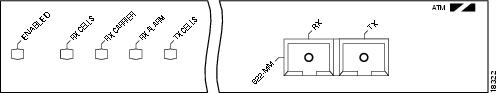
After system initialization, the enabled LED goes on, indicating that the PA-A3 OC-12 has been enabled for operation.
The following conditions must be met before the PA-A3 OC-12 is enabled:
•![]() The PA-A3 OC-12 is correctly connected and is receiving power.
The PA-A3 OC-12 is correctly connected and is receiving power.
•![]() A valid system software image for the port adapter has been downloaded successfully.
A valid system software image for the port adapter has been downloaded successfully.
•![]() The system recognizes the PA-A3 OC-12.
The system recognizes the PA-A3 OC-12.
If any of these conditions are not met, or if the initialization fails for other reasons, the enabled LED does not go on.
Cables, Connectors, and Pinouts
Use a single-mode or multimode fiber-optic interface cable to connect your Cisco 7500 series router to another router or switch. In general, multimode cables are gray or orange, and single-mode cables are yellow.
Note ![]() Single-mode and multimode fiber-optic cables are available from the following cable vendors: AMP, Anixter, AT&T, Red Hawk, and Siemens. These cables are not available from Cisco Systems.
Single-mode and multimode fiber-optic cables are available from the following cable vendors: AMP, Anixter, AT&T, Red Hawk, and Siemens. These cables are not available from Cisco Systems.
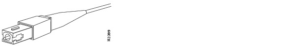
For SONET/SDH single-mode and multimode fiber-optic connections, use one duplex SC-type connector (see Figure 1-4) or two simplex SC-type connectors (see Figure 1-5).
Figure 1-4 Duplex SC Cable Connector
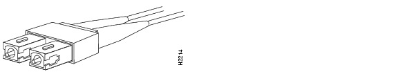
Figure 1-5 Simplex SC Cable Connector
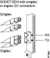
Attach either one duplex fiber-optic cable or two simplex fiber-optic cables between the port adapter and the device to which the port adapter is connected. Observe the receive (RX) and transmit (TX) cable relationship shown in Figure 1-6.
Figure 1-6 Attaching Simplex or Duplex Fiber Cables
The following warnings apply when you work with fiber-optic cable ports.

Warning ![]() Invisible laser radiation can be emitted from the aperture of the port when no cable is connected. Avoid exposure to laser radiation and do not stare into open apertures.
Invisible laser radiation can be emitted from the aperture of the port when no cable is connected. Avoid exposure to laser radiation and do not stare into open apertures.
Warning ![]() Class 1 laser product (single-mode).
Class 1 laser product (single-mode).
Warning ![]() Class 1 LED product (multimode).
Class 1 LED product (multimode).
Port Adapter Slot Locations on the Supported Platform
This section discusses port adapter slot locations on the supported platform. The illustrations that follow suarize slot location conventions.
VIP Slot Numbering
Figure 1-7 shows a partial view of a VIP motherboard with installed port adapters. With the motherboard oriented as shown in Figure 1-7, the left port adapter is in port adapter slot 0, and the right port adapter is in port adapter slot 1. The slots are always numbered 0 and 1.
Figure 1-7 VIP Motherboard with Two Port Adapters Installed—Horizontal Orientation
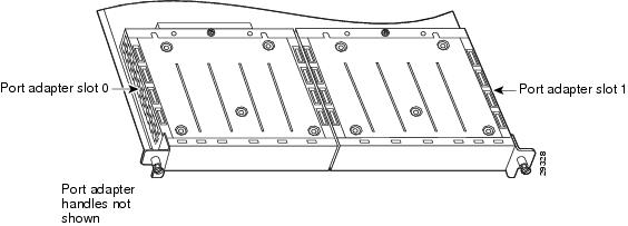
Note ![]() In the Cisco 7507, and Cisco 7513 chassis, the VIP motherboard is installed vertically. In the Cisco 7505 chassis, the VIP motherboard is installed horizontally.
In the Cisco 7507, and Cisco 7513 chassis, the VIP motherboard is installed vertically. In the Cisco 7505 chassis, the VIP motherboard is installed horizontally.
When a dual-width port adapter is installed on a VIP motherboard (see Figure 1-8), the port adapter is always considered to be in port adapter slot 0.
Figure 1-8 VIP Motherboard with a Dual-Width Port Adapter Installed—Horizontal Orientation
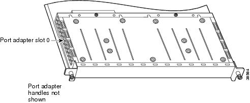
Note ![]() In the Cisco 7507, and Cisco 7513 chassis, the VIP motherboard is installed vertically. In the Cisco 7505 chassis, the VIP motherboard is installed horizontally as shown in Figure 1-9.
In the Cisco 7507, and Cisco 7513 chassis, the VIP motherboard is installed vertically. In the Cisco 7505 chassis, the VIP motherboard is installed horizontally as shown in Figure 1-9.
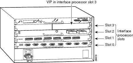
Interface processor slots are numbered as shown in Figure 1-9.
Figure 1-9 Interface Slot Numbers—Cisco 7505 Shown
Identifying the Interface Address
This section describes how to identify the interface address for a PA-A3 OC-12 installed on a VIP in a Cisco 7500 series router. Interface addresses specify the actual physical location of each interface on a router or switch.
The interface on a PA-A3 OC-12 installed on a VIP maintains the same address regardless of whether other interface processors are installed or removed. However, when you move a VIP to a different slot, the interface processor slot number changes to reflect the new interface processor slot.
For example, the address of the PA-A3 OC-12 is 3/0/0 when installed in interface processor slot 3. (See Figure 1-9.) If the PA-A3 OC-12 were in interface processor slot 2, its address would be 2/0/0.
Note ![]() Interface ports are numbered from left to right starting with 0.
Interface ports are numbered from left to right starting with 0.
Table 1-3 explains how to identify interface addresses.
Note ![]() Although the processor slots in the 7-slot Cisco 7507 and the 13-slot Cisco 7513 and Cisco 7576 are vertically oriented and those in the 5-slot Cisco 7505 are horizontally oriented, all Cisco 7500 series routers use the same method for slot and port numbering.
Although the processor slots in the 7-slot Cisco 7507 and the 13-slot Cisco 7513 and Cisco 7576 are vertically oriented and those in the 5-slot Cisco 7505 are horizontally oriented, all Cisco 7500 series routers use the same method for slot and port numbering.
 Feedback