Configuring the Cisco uBR-MC28C Cable Modem Card
Available Languages
Table Of Contents
Configuring the Cisco uBR-MC28C Cable Modem Card
Related Features and Technologies
Supported Standards, MIBs, and RFCs
Configuring the Cisco uBR-MC28C Cable Modem Card
Verifying Downstream Center Frequency
cable downstream interleave-depth
cable upstream differential-encoding
cable upstream freq-adj averaging
cable upstream modulation-profile
Configuring the Cisco uBR-MC28C Cable Modem Card
This feature module describes configuring the Cisco uBR-MC28C cable modem card. The card contains two downstream and eight upstream ports configured in two independent Cable Modem Termination System (CMTS) media access control (MAC) domains. A MAC domain is a collection of upstream and downstream channels for which a single MAC allocation and management protocol operates. Each domain on the Cisco uBR-MC28C cable modem card includes one downstream and four upstream ports. Both domains operate independently of each other.
This feature module includes the following sections:
•
Supported Standards, MIBs, and RFCs
Feature Overview
The Cisco uBR-MC28C cable modem card resides in a Cisco uBR7200 series universal broadband router and supports downstream and upstream traffic to and from Data-Over-Cable Service Interface Specification (DOCSIS)-based cable modems (CMs). The card supports 6-MHz National Television Systems Committee (NTSC) channel operation, using standard (STD), Harmonic Related Carrier (HRC), or Incremental Related Carrier (IRC) frequency plans conforming to EIA-S542. The card supports downstream channels in the 54-to-860 MHz range, therefore, with upstream ranges of 5 to 42 MHz.

Note
The Cisco uBR-MC28C cable modem card contains two downstream modulators and eight upstream demodulators with the following modulation defaults beginning in Cisco IOS Release 12.1(2)EC1:
•
•
These values are based on the Cisco default modulation profile #1 that ships with product. Modulation profile #1 values are illustrated below:
cmts1# show cable modulation-profileMod IUC Type Preamb Diff FEC FEC Scrambl Max Guard Last Scrambl Preamblength enco T CW seed B time CW offsetBYTES size size size short1 request qpsk 64 no 0x0 0x10 0x152 1 8 no yes 9521 initial qpsk 128 no 0x5 0x22 0x152 0 48 no yes 8961 station qpsk 128 no 0x5 0x22 0x152 0 48 no yes 8961 short qpsk 72 no 0x5 0x4B 0x152 6 8 yes yes 9441 long qpsk 80 no 0x8 0xDC 0x152 0 8 yes yes 936interface Cable4/0ip address 10.20.115.33 255.255.255.224ip helper-address 10.0.0.2load-interval 30no keepalivecable spectrum-group 1cable insertion-interval 100cable downstream annex Bcable downstream modulation 64qamcable downstream interleave-depth 32cable downstream frequency 576000000cable upstream 0 spectrum-group 2no cable upstream 0 shutdownno cable upstream 1 shutdownno cable upstream 2 shutdownno cable upstream 3 shutdownendThe Cisco uBR-MC28C cable modem card supports all DOCSIS 1.0-specified Annex B radio frequency (RF) data rates, channel widths, and modulation schemes. Table 1 shows the supported DOCSIS data rates. The card outputs +42 dBmV and +/- 2 dBmV.
Table 1 DOCSIS Data Rates

Caution

Tips
The Cisco uBR-MC28C cable modem card contains a color-coded label that identifies and groups the two supported downstream-to-upstream port sets. Figure 1 shows the dual downstream and upstream port pairs.
Figure 1 Cisco
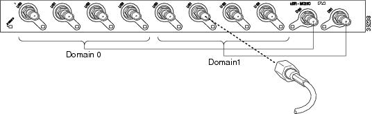
uBR-MC28C Face Plate View
The two downstream ports are labelled DS0 and DS1. Their corresponding upstream ports are labelled U0 through U3, applicable to each port set. To configure the Cisco uBR-MC28C cable modem card, use the interface type slot/port commands:
•
•
•
Table 2 maps the Cisco uBR-MC28C cable modem card's physical port domains and interfaces.
Table 2
Interface to Port Mapping
Note
The card can be housed in a Cisco uBR7223, Cisco uBR7246, or the Cisco uBR7246 VXR universal broadband router. The card supports synchronization with a Cisco clock card in a Cisco uBR7246 VXR. The card distributes the clock signal to CMs supporting the clock feature set that are attached to specific network segments.
Benefits
The Cisco uBR-MC28C cable modem card:
•
•
•
•
–
–
•
Restrictions
Using the Cisco uBR-MC28C cable modem card:
•
Note
•
•
•
•
Related Features and Technologies
Features that can be used with the Cisco uBR-MC28C cable modem card include:
•
http://www.cisco.com/univercd/cc/td/doc/product/cable/cab_r_sw/spec_mgt.htm•
http://www.cisco.com/univercd/cc/td/doc/product/cable/cab_r_sw/hccpfeat.htmRelated Documents
For other information on Cisco uBR7200 series cable modem cards, refer to the following documents:
•
•
•
•
•
Supported Platforms
All current Cisco uBR7200 series universal broadband routers support the Cisco uBR-MC28C cable modem card. These include:
•
•
•
Supported Standards, MIBs, and RFCs
Standards
•
•
MIBs
•
Note
for MIB listings and descriptions.
•
RFCs
•
Note
Prerequisites
Before you configure the Cisco uBR-MC28C cable modem card:
•
–
–
–
Note
http://www.cisco.com/univercd/cc/td/doc/product/cable/cab_rout/cr72hig/index.htm
•
–
–
–
–
–
http://www.cisco.com/univercd/cc/td/doc/product/cable/cab_rout/cr72scg/index.htm•
Configuration Tasks
To configure the Cisco uBR-MC28C cable modem card, perform the following tasks:
•
Note
•
–
–
–
•
–
–
–
Note
Configuring the Cisco uBR-MC28C Cable Modem Card
Follow Step 1 through Step 7 for the second MAC domain. Save your settings to nonvolatile random access memory (NVRAM) to ensure that the system retains the settings after a power cycle:
Router# copy running startVerifying Your Settings
To verify your settings, enter the show running-config command:
Router# show running-configVerifying Upstream Settings
To verify upstream settings, enter the show contr command:
Router# show contr c4/0Interface Cable4/0Hardware is MC28C(F-connector)
BCM3210 revision=0x56B2idb 0x6158A4CC MAC regs 0x3E104000 PLX regs 0x3E000000rx ring entries 1024 tx ring entries 128 MAP tx ring entries 128Rx ring 0x4B09CCC0 shadow 0x615A7E78 head 0Tx ring 0x4B09ED00 shadow 0x615A8EE8 head 6 tail 6 count 0MAP Tx ring 0x4B09F140 shadow 0x615A9358 head 16 tail 16 count 0MAP timer sourced from slot 4throttled 0 enabled 0 disabled 0Rx:spurious 0 framing_err 0 hcs_err 0 no_buffer 0 short_pkt 0no_enqueue 0 no_enp 0 miss_count 0 latency 0invalid_sid 0 invalid_mac 0 bad_ext_hdr_pdu 0 concat 0 bad-concat 0Tx: full 0 drop 0 stuck 0 latency 0MTx:full 0 drop 0 stuck 0 latency 96Slots 0 NoUWCollNoEngy 0 FECorHCS 4 HCS 4Req 28448325 ReqColl 0 ReqNoise 23 ReqNoEnergy 28448302ReqData 0 ReqDataColl 0 ReqDataNoise 0 ReqDataNoEnergy 0Rng 0 RngColl 0 RngNoise 0FECBlks 4 UnCorFECBlks 4 CorFECBlks 0MAP FIFO overflow 0, Rx FIFO overflow 0, No rx buf 0Bandwidth Requests= 0x0Piggyback Requests= 0x0Ranging Requests= 0x0Timing Offset = 0x0Bad bandwidth Requests= 0x0No MAP buffer= 0x0Cable4/0 Downstream is upFrequency 576.0000 MHz, Channel Width 6 MHz, 64-QAM, Symbol Rate 5.056941 MspsFEC ITU-T J.83 Annex B, R/S Interleave I=32, J=4Downstream channel ID:1Verifying Downstream Center Frequency
To verify the downstream center frequency of each domain, enter the show controllers cable slot/port downstream command:
Router# show controllers cable 4/0 downstreamCable4/0 Downstream is upFrequency 576.0000MHz, Channel Width 6MHz, 64-QAM, Symbol Rate5.056941 MspsFEC ITU-T J.83 Annex B, R/S Interleave I=32, J=4Downstream channel ID: 0Command Reference
Command reference pages are included for the following configuration commands:
•
•
•
•
•
•
•
•
•
•
•
•
•
•
•
•
•
•
•
•
•
•
•
•
•
•
•
cable downstream frequency
To have the downstream center frequency reflect the digital carrier frequency of the downstream RF carrier for that downstream port, use the cable downstream frequency command in cable interface configuration mode.
cable downstream frequency down-freq-hz
Syntax Description
Defaults
Disabled
Command Modes
Cable interface configuration
Command History
Usage Guidelines
The downstream frequency is an information-only parameter. The configuration controlling the actual digital carrier frequency is set by the external upconverter. The display parameter you set for a Cisco uBR7200 cable modem card should match the digital carrier frequency you set when you configure the upconverter. The cable downstream frequency command has no effect on the external upconverter; it is informational only.
Examples
The following example shows how to set the downstream center frequency value:
router(config-if)# cable downstream frequency 96000000cable downstream if-output
To activate a downstream port on a cable modem card for digital data transmissions over the cable plant, use the cable downstream if-output command in cable interface configuration mode. To disable the intermediate frequency (IF) carrier, use the no form of this command.
cable downstream if-output
no cable downstream if-output
Syntax Description
This command has no arguments or keywords.
Defaults
Downstream carrier is enabled
Command Modes
Cable interface configuration
Command History
Usage Guidelines
Caution
Examples
The following example shows how to enable downstream port 0 on a cable modem card installed in slot 6 of a Cisco uBR7200 series:
router(config-if)# cable 6/0 cable downstream if-outputcable downstream interleave-depth
To set the downstream interleave depth, use the cable downstream interleave-depth command in cable interface configuration mode. To restore the default setting, use the no form of this command.
cable downstream interleave-depth {8 | 16 | 32 | 64 | 128}
no cable downstream interleave-depth
Syntax Description
Defaults
The cable downstream interleave-depth default value is 32.
Command Modes
Cable interface configuration
Command History
Usage Guidelines
This command sets the minimum latency for the system. A higher interleave depth provides more protection from bursts of noise on the Hybrid Fiber Coax (HFC) system. A higher depth, however, also increases downstream latency which slows TCP/IP throughput in some configurations. Table 3 shows interleave characteristics and relationships. The command applies to Cisco "C-based" cable modem cards and the Cisco uBR-MC16S. The command does not apply to the Cisco uBR-MC16E.
Caution
Table 3 Interleave Characteristics and Relationships
Examples
The following example shows how to set the downstream interleave depth to 128 microseconds:
router(config-if)# cable downstream interleave-depth 128cable downstream modulation
To set the modulation format for a downstream port on a cable modem card, use the cable downstream modulation command in cable interface configuration mode.
cable downstream modulation {64qam | 256qam}
Syntax Description
64qam
Modulation rate is 6 bits per downstream symbol.
256qam
Modulation rate is 8 bits per downstream symbol.
Defaults
The cable downstream modulation default is 64qam.
Command Modes
Cable interface configuration
Command History
Usage Guidelines
Downstream modulation defines the speed in bits per second at which data travels downstream to the cable modem. A symbol is the basic unit of modulation; 64 QAM encodes 6 bits per symbol; 256 QAM encodes 8 bits per symbol.
Note
Caution
Examples
The following example shows how to set the downstream modulation to 256 QAM from the default of 64 QAM:
router(config-if)# cable downstream modulation 256qamcable downstream rate-limit
To enable DOCSIS rate limiting on downstream traffic, use the cable downstream rate-limit command in cable interface configuration mode. To disable DOCSIS rate limiting on downstream traffic, use the no form of this command.
cable downstream rate-limit [token-bucket [[shaping [granularity msec | max-delay msec]] | weighted-discard] [exp-weight]
no cable downstream rate-limit
Syntax Description
Defaults
The default value is token-bucket
Command Modes
Cable interface configuration
Command History
11.3(6) NA
This command was introduced.
12.0(4)XI
The shaping keyword was added.
12.0(5)T1, 12.1(1)EC1
Support for shaping was added.
Usage Guidelines
When you enter this command without an option, the token-bucket option is used.
Examples
The following example shows how to apply the token-bucket filter algorithm:
router(config-if)# cable 6/0 cable downstream rate-limit token-bucketcable insertion-interval
To configure the interval between consecutive initial ranging slots on an upstream, use the cable insertion-interval interface configuration command. To configure the automatic setting and ignore any minimum or maximum time settings, use the no form of this command.
cable insertion-interval [fixed-inrvl | automatic [min-intrvl | max-intrvl]]
no cable insertion-interval
Syntax Description
Defaults
The default for the insertion interval is automatic. This setting dynamically varies the frequency of initial ranging upstream slots between 50 milliseconds to 2 seconds.
Command Modes
Cable interface configuration
Command History
11.NA
This command was introduced.
12.1 T
This command was modified to adjust the algorithm.
Usage Guidelines
Use this command to specify the minimum and maximum duration between initial ranging opportunities that appear in MAP messages the Cisco uBR7200 series sends. MAP messages define the precise time intervals for cable modems.
The default insertion interval setting (automatic) configures the Cisco uBR7200 series to automatically vary the initial ranging times available to new cable modems that attempt to join the network between 50 milliseconds and 2 seconds.
Use the automatic keyword with this command when you have to bring a large number of cable modems online (for example, after a major power failure). Override the automatic keyword by specifying an insertion interval.
Examples
The following example shows how to specify automatic insertion intervals:
router(config-if)# cable insertion-interval automaticThe following example shows how to specify minimum insertion interval to 100 ms:
Router(config-if)# cable insertion-interval min 100Related Commands
Command
Description
Specifies automatic or fixed start and stop values for data backoff.
Specifies automatic or configured initial ranging backoff calculation.
cable intercept
To allow the CMTS to forward all traffic to and from a particular cable modem to a data collector located at particular User Datagram Protocol (UDP) port, use the cable intercept command cable interface configuration command. To deactivate this function, use the no form of this command.
cable intercept [mac-address] ip-address udp-port
no cable intercept
Syntax Description
mac-address
Specifies the MAC address.
ip-address
Specifies the IP address.
udp-port
Specifies the destination UDP port number for the intercept stream. Valid range is 0 to 65,535.
Defaults
Disabled
Command Modes
Cable interface configuration
Command History
12.0(5)T1
This command was introduced on the T train.
12.0(6)SC
This command was introduced on the SC train.
12.1(2)EC
This command was introduced on the EC train.
Usage Guidelines
When this command is activated, the Cisco uBR7200 series universal broadband router examines each packet for the desired MAC address. When a matching MAC address is found for either the origination or destination endpoint, a copy of the packet is encapsulated into a UDP packet. The packet is then sent to the specified server at the given IP address and port.
Note
This command can be used to comply with the United States Federal Communications Assistance for Law Enforcement Act (CALEA) and other law enforcement wiretap requirements for voice communications.
Examples
The following command shows how to specify the destination IP address and UDP port number for the Cisco uBR7200 series universal broadband router:
(config-if)# cable intercept 0080.fcaa.aabb 3.12.13.8 512cable modulation-profile
To define the modulation profile, use the cable modulation-profile global configuration command. Use the no form of this command to remove the specified modulation profile.
cable modulation-profile profile iuc fec-tbytes fec-len burst-len guard-t mod scrambler seed diff pre-len last-cw uw-len
no cable modulation-profile profile iuc fec-tbytes fec-len burst-len guard-t mod scrambler seed diff pre-len last-cw uw-len
Syntax Description
Defaults
Modulation profile #1 with the qpsk option is the default.
Command Modes
Global configuration
Command History
Usage Guidelines
A modulation profile is a collection of six burst profiles that are sent out in an Upstream Channel Descriptor (UCD) message to configure a cable modem's transmit parameters for the following upstream message types: request, initial maintenance, station maintenance, short grant, and long grant.
For Cisco cable modem cards other than the Cisco uBR-MC11 FPGA and the Cisco uBR-MC16B, you can use the no cable modulation-profile command to remove all modulation profiles except modulation profile 1. In the case of modulation profile 1, the no cable modulation-profile command sets all of the parameters in a burst to default values.
Note
Tips
Caution
Turning the scrambler off might cause packet loss; recommended only in lab testing environments.
Errors or incompatible configurations in burst profiles can cause cable modems to drop connectivity, drop short or long data packets, or even to fail to connect to the network.You can build a burst profile set for which a DOCSIS receiver cannot receive the modem's transmission.
The 160 Ksymbol/sec and 2560 Ksymbol/sec data rates are highly sensitive to unique word length, preamble length, and FEC sizing. Incorrect choices for these values can cause poor, or no, connectivity at these symbol rates.
Examples
The following example shows how to define the burst parameters for profile 2 as follows:
The request burst is defined to have 0 fec-tbytes, 16 kbytes fec-len, a burst-len of 1, a guard time of 8, a mod value of qpsk, scrambler enabled with a seed value of 152, differential encoding disabled, a preamble length of 64 bits, a fixed code word length, and 8-bit unique words for upstream unique word length. The remaining initial, station, short, and long bursts are defined in similar fashion for profile 2.
Router(config)# cable modulation-profile 2 request 0 16 1 8 qpsk scrambler 152 no-diff 64
fixed uw8
Router(config)# cable modulation-profile 2 initial 5 34 0 48 qpsk scrambler 152 no-diff 128 fixed uw16Router(config)# cable modulation-profile 2 station 5 34 0 48 qpsk scrambler 152 no-diff 128 fixed uw16Router(config)# cable modulation-profile 2 short 6 75 6 8 16qam scrambler 152 no-diff 144 fixed uw8Router(config)# cable modulation-profile 2 long 8 220 0 8 16qam scrambler 152 no-diff 160 fixed uw8
Note
Related Commands
cable qos profile
To configure a quality of service (QoS) profile, use the cable qos profile command in global configuration mode. To either set default values for profile group numbers 1 or 2, or to remove the QoS profile if no specific parameters remain, use the no form of this command.
cable qos profile {groupnum | grant-interval {interval} | grant-size {size} | guaranteed-upstream {rate} | ip-precedence {value} | max-burst {rate} | max-downstream {rate} | max-upstream {rate} | name {string} | priority {value} | privacy | tos-overwrite {value}}
no cable qos profile {groupnum | grant-interval {interval} | grant-size {size} | guaranteed-upstream {rate} | ip-precedence {value} | max-burst {rate} | max-downstream {rate} | max-upstream {rate} | name {string} | priority {value} | privacy | tos-overwrite {value}}
Syntax Description
Defaults
No default behavior or values.
Command Modes
Global configuration
Command History
Examples
The following example shows how to configure QoS profile 4 with a guaranteed upstream rate of 8 kbps, maximum transmission burst of 16 minislots, maximum downstream rate of 128 kbps, a priority of 4, cable baseline privacy set, and a tos-overwrite mask and value byte (in hex) of 0x2:
router(config)# cable qos profile 4 guaranteed-upstream 8router(config)# cable qos profile 4 max-burst 16router(config)# cable qos profile 4 max-downstream 128router(config)# cable qos profile 4 privacyrouter(config)# cable qos profile 4 priority 4router(config)# cable qos profile 4 tos-overwrite 0xA0 0xE0Related Commands
cable qos permission
Specifies permission for updating the cable router QoS table.
show cable qos profile
Displays cable router QoS profiles.
cable upstream channel-width
To specify an upstream channel width for an upstream port, use the cable upstream channel-width command in cable interface configuration mode. To set the channel width back to the default setting of 1600,000 Hz, use the no form of this command.
cable upstream usport channel-width first-choice-width [last-choice-width]
no cable upstream usport channel-width
Syntax Description
Defaults
1,600,000 Hz
Command Modes
Cable interface configuration
Command History
11.3(5)NA
This command was introduced.
12.0(4)XI
The last-choice-width argument was added.
12.0(7)XR2
The command was updated to support the Cisco uBR-MC16S.
Usage Guidelines
The last-choice-width parameter is supported only by the Cisco uBR-MC16S cable modem card. When the Cisco uBR-MC16S is installed, the system attempts to increase the channel width from the first-choice-width value to the last-choice-width value one step at a time.
Examples
The following example configures upstream port 2 with a channel width of 200,000 Hz (which is equivalent to a symbol rate of 160 kilosymbols/second):
router(config-if)# cable upstream 2 channel-width 200000The following example configures upstream port 3 to step from a channel width of 1,600,000 Hz to a channel width of 3,200,000 Hz in increments of 200,000 Hz:
router(config-if)# cable upstream 3 channel-width 1600000 3200000Related Commands
cable upstream concatenation
To turn concatenation on or off from the CMTS, use the cable upstream concatenating cable interface configuration command. To turn off concatenation, use the no form of this command.
cable upstream n concatenation
no cable upstream n concatenation
Syntax Description
Defaults
On
Command Modes
Cable interface configuration
Command History
Usage Guidelines
Concantenation is part of DOCSIS 1.0 extension support. Concatenation must be supported at both the CMTS and the CM.
DOCSIS concatenation combines multiple upstream packets into one packet to reduce packet overhead and overall latency, and increase transmission efficiency. Using concatenation, a DOCSIS cable modem needs to make only one bandwidth request for a concatenated packet, compared to making bandwidth requests for each individual packet. This technique is especially effective for bursty real-time traffic such as voice calls. Concatenation support improves upstream per cable modem (CM) data throughput.
The current Cisco uBR7200 series cable modem card driver can only receive one MAC frame in a data burst. Thus, the CM must make explicit bandwidth requests for every packet it wishes to send upstream. This limits the maximum upstream data throughput a CM receives due to the inherent request-to-grant round-trip latency of the HFC system incurred by every packet. To increase this per-CM upstream throughput, the Cisco uBR7200 driver has been enhanced to receive a concatenated burst of multiple MAC frames from the same CM.
Note
cable upstream data-backoff
To specify automatic or fixed start and stop values for the data backoff, use the cable upstream data-backoff command in cable interface configuration mode. To use the default data backoff values, use the no form of this command.
cable upstream usport data-backoff {automatic | start end}
no cable upstream usport data-backoff
Syntax Description
Defaults
automatic
Command Modes
Cable interface configuration
Command History
Usage Guidelines
The DOCSIS-specified method of contention resolution for cable modems used to send data or requests on the upstream channel is a truncated binary exponential back-off with the initial backoff window and the maximum backoff window controlled by the CMTS. The Cisco uBR7200 series router specifies back-off window values for both data and initial ranging, and sends these values downstream as part of the Bandwidth Allocation Map (MAP) MAC message. The values are power-of-two values. For example, a value of 4 indicates a window between 0 and 15; a value of 10 indicates a window between 0 and 1023.
Cisco recommends that you use the automatic settings for data backoff.
Examples
The following example shows how to set the automatic data backoff values for port 2:
router(config-if)# cable upstream 2 data-backoff automaticRelated Commands
Command
Description
Specifies automatic or configured initial ranging backoff calculation.
cable insertion-interval
Configures the interval between consecutive initial ranging slots on an upstream.
cable upstream differential-encoding
To enable differential encoding on upstream traffic to a specified cable interface, use the cable upstream differential-encoding command in cable interface configuration mode. To disable this function, use the no form of this command.
cable upstream usport differential-encoding
no cable upstreamusport differential-encoding
Syntax Description
Defaults
Enabled
Command Modes
Cable interface configuration
Command History
Usage Guidelines
To verify whether or not upstream differential encoding is activated, enter the show running-config command and look for the cable interface configuration information. If upstream differential encoding is enabled, a differential encoding entry is displayed in the show running-config output. If upstream differential encoding is disabled, no differential encoding entry is displayed in the output.
If you are having trouble, make sure that the cable connections are not loose or disconnected; the cable modem card is firmly seated in its chassis slot; the captive installation screws are tight; you have entered the correct slot and port numbers; and you selected a valid frequency for your router.
Examples
The following example shows how to enable differential encoding for upstream port 2:
Router(config-if)# cable upstream 2 differential-encodingcable upstream fec
To enable upstream forward error correction (FEC), use the cable upstream fec command in cable interface configuration mode. To disable FEC, use the no form of this command.
cable upstream usport fec
no cable upstream usport fec
Syntax Description
Defaults
Enabled
Command Modes
Cable interface configuration
Command History
Usage Guidelines
The Cisco uBR7200 series uses forward error correction (FEC) to attempt to correct any upstream data that might have been corrupted. To use this feature, activate FEC on the upstream RF carrier. When FEC is activated, the Cisco uBR7200 series commands all cable modems on the network to activate FEC.
Examples
The following example shows how to activate upstream forward error correction:
router (config-if)# cable upstream 0 fecRelated Commands
cable upstream fec-strength
To override the forward error correction (FEC) setting specified in the modulation profile for this upstream channel, use the cable upstream fec-strength command in cable interface configuration mode. To restore the default value, use the no form of this command.
cable upstream usport fec-strength t-bytes
no cable upstream usport fec-strength
Syntax Description
Defaults
No default behavior or values.
Command Modes
Cable interface configuration
Command History
Examples
The following example shows how to configure the cable upstream fec-strength command:
router(config-if)# cable upstream 2 fec-strength 3Related Commands
cable upstream freq-adj averaging
To control power adjustments on a Cisco uBR7200 series by setting the frequency threshold, use the cable upstream freq-adj averaging interface configuration command. To disable power adjustments, use the no form of this command.
cable upstream n freq-adj averaging % of frequency adjustment
no cable upstream freq-adj averaging
Syntax Description
Defaults
No default behavior or values.
Command Modes
Interface configuration
Command History
Examples
The following example shows how to change the power adjustment method when the frequency adjustment packet count reaches 50 percent:
Router(config-if)#cable upstream 0 freq-adj averaging 50Related Commands
cable upstream frequency
To enter a fixed frequency of the upstream radio frequency (RF) carrier for an upstream port, use the cable upstream frequency command in cable interface configuration mode. To restore the default value for this command, use the no form of this command.
cable upstream usport frequency up-freq-hz
no cable upstream usport frequency up-freq-hz
Syntax Description
Defaults
Dynamic (not fixed frequency)
Command Modes
Cable interface configuration
Command History
Usage Guidelines
The upstream channel frequency of your RF output must be set to comply with the expected input frequency of your Cisco cable modem card. To configure an upstream channel frequency, you may:
•
•
To configure the default upstream frequency (which is no fixed frequency), enter the cable upstream usport frequency command without specifying a center frequency.
Examples
The following example shows how to configure the upstream center frequency for port 0, located in slot 6, to 5,700,000 Hz:
Router(config-if)# cable upstream 0 frequency 5700000The following example shows how to allow the Cisco uBR7200 series to dynamically specify a center frequency for the upstream port 0:
Router(config-if)# cable upstream 0 frequencycable upstream minislot-size
To specify the minislot size (in ticks) for a specific upstream interface, use the cable upstream minislot-size command in cable interface configuration mode. To set the default minislot size of 8 if this is valid for the current channel width setting, use the no form of this command.
cable upstream usport minislot-size size
no cable upstream usport minislot-size
Syntax Description
Defaults
The default settings vary, depending on the specified minislot sizes. The minislot size has a range of values between 2 and 128 and default values for these minislot sizes range between 4 and 64.
Command Modes
Cable interface configuration
Command History
Usage Guidelines
Caution
Examples
The following example shows how to set the minislot size on upstream port 4 to 16 (or 256 symbols):
router(config-if)# cable upstream 4 minislot-size 16cable upstream modulation-profile
To assign a modulation profile to an interface, use the cable upstream modulation-profile interface configuration command. Use the no form of this command to assign the default primary modulation profile (profile #1) to the interface.
cable upstream n modulation-profile primary-profile-number secondary-profile-number
no cable upstream n modulation-profile primary-profile-number secondary-profile-number
Syntax Description
n
Port number on the cable modem slot.
primary-profile number
Default modulation profile added to the interface.
secondary-profile number
Additional modulation profile added to the interface.
Defaults
Primary modulation profile (profile #1).
Command Modes
Interface configuration
Command History
11.3 NA
This command was first introduced.
12.0(7)XR2
This command was used.
12.1(3a)EC1
This command was modified to add the primary-profile-number and secondary-profile-number.
Usage Guidelines
You can configure modulation profiles with fixed upstream frequencies or on interfaces with assigned spectrum groups. The dynamic upstream modulation feature uses modulation profiles to track upstream signal quality. It checks that the upstream signal can support the configured modulation scheme, and adjusts to a more robust modulation scheme, if necessary. When return path conditions improve, it returns the upstream channel to the higher modulation scheme.
Examples
The following example shows how to assign the primary modulation profile 2 and the secondary modulation profile 1 to port (interface) 0:
Router(config-if)# cable upstream 0 modulation-profile 2 1cable upstream power-adjust
To control power adjustment methods on the Cisco uBR7200 series, use the cable upstream power-adjust command in interface configuration mode. To disable power adjustments, use the no form of this command.
cable upstream n power-adjust [continue] [noise % of power adjustment] [threshold #]
no cable upstream power-adjust
Syntax Description
Defaults
No default behavior or values.
Command Modes
Interface configuration
Command History
Examples
The following example shows how to change the power adjustment method when the percentage of power adjustment packets reaches 50 percent:
router(config-if)# cable upstream 0 power-adjust noise 50Related Commands
cable upstream power-level
To set the input power level for the upstream radio frequency (RF) carrier in decibels per millivolt (dBmV), use the cable upstream power-level command in cable interface configuration mode. To restore the default value for this command, use the no form of this command.
cable upstream usport power-level dbmv
no cable upstream usport power-level dbmv
Syntax Description
usport
Specifies the upstream port number.
dbmv
Decibels per millivolt designating the upstream signal input power level. Valid range is -10 dBmV to 25 dBmV.
Defaults
0 dBmV
Command Modes
Cable interface configuration
Command History
Usage Guidelines
The Cisco uBR7200 series controls the output power levels of the cable modems to meet the desired upstream input power level. The nominal input power level for the upstream RF carrier is specified in decibels per millivolt (dBmV). The default setting of 0 dBmV is the optimal setting for the upstream power level.
The valid range for the input power level depends on the data rate. At 1.6 MHz, the valid range is -10 dBmV to 25 dBmV. Higher values cause the modems to increase their transmit power, achieving a greater carrier-to-noise ratio. If your power levels operate at greater than the maximum valid level, you must use an attenuator to bring the power level to within the valid range.
Caution
You should not adjust your input power level by more than 5 dB in a 30-second interval. If you increase the power level by more than 5 dB within 30 seconds, cable modem service on your network will be disrupted. If you decrease the power level by more than 5 dB within 30 seconds, cable modems on your network will be forced offline.
When you run cable upstream 0 power-level, Cisco recommends that the adjacent channel not have a large variation. The recommended maximum input power variance is 5 to 6 dBmV.
Examples
The following example shows how to set the input power level for upstream port 0 to -5 dBmV:
router(config-if)# cable upstream 0 power-level -5Related Commands
cable upstream range-backoff
To specify automatic or configured initial ranging backoff calculation, use the cable upstream range-backoff command in cable interface configuration mode. To set default values, use the no form of this command.
cable upstream usport range-backoff {automatic | start end}
no cable upstream usport range-backoff
Syntax Description
Defaults
automatic
Command Modes
Cable interface configuration
Command History
Usage Guidelines
The DOCSIS-specified method of contention resolution for cable modems used to send data or requests on the upstream channel is a truncated binary exponential back-off with the initial backoff window and the maximum backoff window controlled by the CMTS. The Cisco uBR7200 series router specifies backoff window values for both data and initial ranging, and sends these values downstream as part of the Bandwidth Allocation Map (MAP) MAC message. The values are power-of-two values. For example, a value of 4 indicates a window between 0 and 15; a value of 10 indicates a window between 0 and 1023.
The automatic setting is optimized for a maximum of 250 cable modems per upstream port. Set manual values for data backoff windows only when operating with more than 250 cable modems per upstream port.
Examples
The following example shows how to set the range backoff to automatic for upstream port 2:
router(config-if)# cable upstream 2 range-backoff automaticRelated Commands
Command
Description
Specifies automatic or fixed start and stop values for data backoff.
cable insertion-interval
Configures the interval between consecutive initial ranging slots on an upstream.
cable upstream rate-limit
To set DOCSIS rate limiting for an upstream port on a cable modem card, use the cable upstream rate-limit command in cable interface configuration mode. To disable DOCSIS rate limiting for the upstream port, use the no form of this command.
cable upstream usport rate-limit [token-bucket [shaping]]
no cable upstream usport rate-limit
Syntax Description
Defaults
Token bucket algorithm with traffic shaping.
Command Modes
Cable interface configuration
Command History
11.3(6)NA
This command was introduced.
11.3(9)NA
The shaping keyword was added.
Usage Guidelines
Upstream rate limiting allows upstream bandwidth requests from rate-exceeding cable modems to be buffered without incurring TCP-related timeouts and retransmits. This enables the Cisco uBR7200 series to enforce the peak upstream rate for each cable modem without degrading overall TCP performance for the subscriber CPEs. Upstream grant shaping is per cable modem (SID).
When the token-bucket algorithm is configured, the Cisco uBR7200 series automatically drops packets in violation of allowable upstream bandwidth.
Use of the default value (the upstream port's rate limit) enforces strict DOCSIS-compliant rate limiting. Cisco highly recommends to using the default setting of token-bucket with the shaping option.
Examples
The following example shows how to configure the token bucket filter algorithm with traffic shaping on upstream port 4:
router(config-if)# cable upstream 4 rate-limit token-bucketRelated Commands
cable upstream scrambler
To enable the cable upstream scrambler, use the cable upstream scrambler command in cable interface configuration mode. To restore the default configuration value for this command, use the no form of this command.
cable upstream usport scrambler
no cable upstream usport scrambler
Syntax Description
Defaults
Disabled
Command Modes
Cable interface configuration
Command History
Usage Guidelines
This command causes cable modems to enable their pseudo-random scrambler circuitry to improve the robustness of the upstream receiver on the line card.
The scrambler on the upstream radio frequency (RF) carrier enables cable modems on the HFC network to use built-in scrambler circuitry for upstream data transmissions. The scrambler circuitry improves reliability of the upstream receiver on the cable modem card. The upstream scrambler is activated by default and should not be disabled under normal circumstances.
Caution
Examples
The following example shows how to activate the upstream scrambler:
router(config-if)# cable upstream 0 scrambler#Related Commands
cable upstream shutdown
To disable the upstream port, use the cable upstream shutdown command in cable interface configuration mode. To enable the upstream port, use the no form of this command.
cable upstream usport shutdown
no cable upstream usport shutdown
Syntax Description
Defaults
Upstream port enabled
Command Modes
Cable interface configuration
Command History
Examples
The following example shows how to disable the upstream port:
router(config-if)# cable upstream 0 shutdowncable upstream timing-adjust
To enable upstream timing adjustment for a specified cable interface, use the cable upstream timing-adjust cable interface configuration command. To return to the default values, use the no form of this command.
cable upstream usport timing-adjust {continue sec | threshold sec}
no cable upstream usport timing-adjust {continue sec | threshold sec}
Syntax Description
Defaults
2 seconds for continue and 1 second for threshold.
Command Modes
Cable interface configuration mode
Command History
Usage Guidelines
To verify whether or not upstream timing adjustment is configured and activated, enter the show running-config command and look for the cable interface configuration information. If upstream timing adjustment is enabled, either or both of the continue and threshold timing adjustment entries are displayed in the show running-config output. If both the continue and threshold upstream timing adjustments are disabled, no timing adjustment entry is displayed in the show running-config output.
If you are having trouble, make sure that the cable connections are not loose or disconnected; the cable modem card is firmly seated in its chassis slot; the captive installation screws are tight; and you have entered the correct slot and port numbers.
Note
Examples
The following example shows how to set the upstream time adjustment ranging value to 5 seconds:
CMTS01(config-if)# cable upstream 0 time-adjust continue 5The following example shows how to set the upstream time adjustment threshold value to the default of 12 seconds:
CMTS01(config-if)# cable upstream 0 time-adjust threshold 12
 Feedback